| John Broskie's Guide to Tube Circuit Analysis & Design |
27 May 2020 Post Number 504 Special Thanks to King Heiple
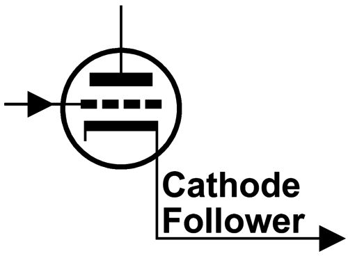
Cathode-Follower OTL
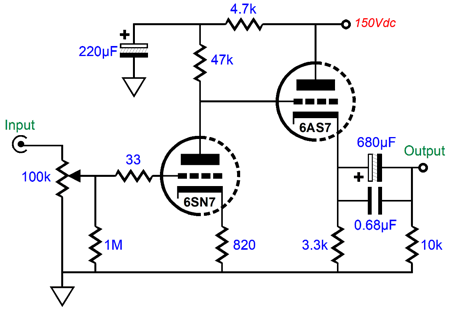
Instantly, I knew that claim of 1W could not be true, as the idle current had to be far too lean to support that claim of 1W. How did I know? Just divide the B+ voltage of 150Vdc by 3.3k ohms and you must get some current flow less than 30mA, which could never deliver the needed peak 0.25A current swing needed for 1W into 32 ohms. SPICE simulations confirmed my evaluation, as only 25mA flowed through the output triode and cathode resistor. Furthermore, negative output voltage swings into 32 ohms didn't exceed 0.8Vpk, which only yields 10mW into 32-ohm loads, not 1W. As I looked at the schematic, I thought that a better choice for an output tube would be either a 6BL7 or 6BX7, as long as the headphone impedance was 300 ohms, as the 3.3k cathode resistor still limited the idle current too much for ever successfully driving low-impedance headphones. I concluded that the DC coupling between the input stage and the cathode follower was a bad idea, as a coupling capacitor would allow the output triode to see a much larger cathode-to-plate voltage, which would allow much great current flow. Another sore spot was the lack of a grid-stopper resistor for the 6AS7 and a wimpy 33-ohm grid-stopper for the 6SN7. Why? Why not use two grid-stoppers and larger valued ones? It's not that they cost a fortune. For example, switching from cheap iron to expensive nickel core laminations in an output transformer is asking a lot, whereas four 10-cent resistors isn't. Grid-stopper resistors are a beneficial idea in grounded-cathode amplifier but essential in a cathode follower. Is this some new audionervosa fad? Dear God, I hope not. A few years back, I saw the insides of an expensive tube power amplifier at the RMAF. I was stunned not to see grid-stopper resistors, as the designer was extremely capable, not someone who just sprinkled fancy boutique parts on circuits from the 1950s. When asked why no grid-stopper resistors, he replied, "They're there." I was just about to inform him that placing them 8 inches away from the tube sockets undermined their effectiveness, when he pointed to a socket and said, "Don't you see it?" He had soldered a surface-mount resistor directly to the tube-socket tab and then soldered the lead wire to the resistor's body. All the electrical benefit, with none of the audionervosa anxiety. Brilliant. Imagine invisible seatbelts for those who fear that seatbelts somehow slow a car's performance down. Okay, back to the circuit at hand, I presented the schematic to Google Reverse Image Search, where you drag an image onto the Google Image Search webpage and Google hunts for its home on the web. Google brought up the headphone amplifier's name, Darkvoice 336SE, and an alternative circuit.
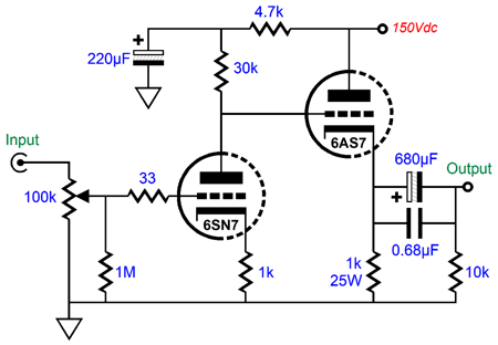
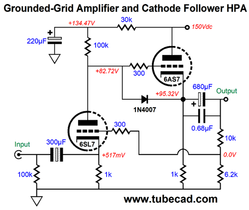
Much better. The 1k cathode resistor for the 6AS7 triode allows far more idle current to flow. I also like the 30k plate resistor for the 6SN7. (Many of the schematics and photos showed three 10µF coupling capacitors in parallel, which is far too low in value to work with 32-ohm headphones.) I ran some SPICE simulations on the circuit and the performance improved substantially. Here is what SPICE revealed. The output is 1Vpk at 1kHz into 32-ohms load.
I researched the headphone amplifier and it received mixed reviews, but mostly good reviews. (Even a bad tube amplifier can sound thrilling if you have never heard one before.) One complaint I encountered more than a few times was hum. The problem is that they didn't specify the frequency. If it were primarily 60Hz, I would look into improving the grounding scheme and replacing the existing heater wires with tightly twisted wires, not the long parallel stretches of stiff wire I saw in the photos. On the other hand, if the hum's frequency was 120Hz, then the power-supply noise was leaking out the output. In SPICE simulations, the PSRR came in at around -20dB, which means that 1/10th of the power-supply noise seeps into the output signal. The obvious workarounds are to beef up the power supply, maybe add a bigger power-supply capacitor or a choke or a regulator. Alternatively, we can get sneaky. The headphones' ground is shared between channels, but it does not have to actually terminate into ground. Post 367 reveals a devious way to just sidestep the leaked power-supply noise.
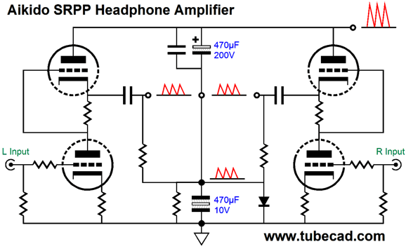
The circuit shown is an SRPP headphone amplifier. The SRPP's PSRR is a poor -6dB (i.e. 50%), so the two capacitors define a 50% AC voltage divider. Thus, we assume that a 10% AC voltage divider will be needed for this headphone amplifier. That is not what SPICE simulations revealed, however, as something closer to 30% yielded the best PSRR enhancement.
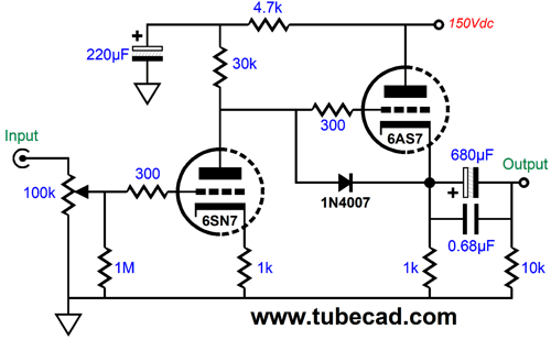
An added advantage this setup offers is that it sidesteps the problem of electrolytic capacitor current leakage. Ideally, a capacitor passes no DC current. Electrolytic capacitors are not ideal. A tiny amount of current leakage, say 0.1mA, against a 10k resistor equals a DC offset of 1V. Of course, when we plug in the 32-ohm headphones, the DC will fall to 3.2mV—but plugging in the headphones will create a popping sound, as the DC offset discharges to the lower level. One workaround is to use a switching headphone jack, so when the headphone plug is removed, the switches shunt the left and right outputs with a 10-ohm resistor to ground. Once the headphone plug is inserted, the switched contacts open, effectively removing the 10-ohm resistors from the circuit. In this setup of using a two-capacitor AC voltage divider, in contrast, the DC offset never develops a DC voltage across the headphones. In addition, the 1kµF and 470µF capacitors effectively create a 320µF capacitor that shunts the B+ voltage to ground, reducing the amount of ripple present on the B+ voltage. Let's return to the original circuit. The easiest modification would be to add a grid-stopper resistor and safety diode.
The diode protects the 6AS7 at start-up, as it limits the maximum cathode-to-grid voltage to about 0.7V, rather than the 150V differential without the diode. The grid-stopper resistors prevent ultra-high-frequency oscillations. All in all, a dollar well spent. The next step we might take would be to replace the 1k cathode resistor with a constant-current source. Why? The constant-current source would slightly improve the performance and it sidesteps the problem of most 25W wire-wound resistors not sounding all that good.
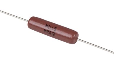
On the other hand, if we replaced the existing 1k resistor with two Mills brand 10W or 12W non-inductive power resistors in series, say two 510-ohm or two 470-ohm resistors, then we would eliminate the last problem nicely. Mills makes great resistors. (If your loudspeaker's crossover holds cheap white rectangular wire-wound sand resistors or metal-oxide power resistors, then replacing them with Mills non-inductive power resistors could equal a DAC $2000 upgrade in sonic improvement, while the resistor only cost $7 each.) On the other hand, the constant-current source offers the advantage of a truly fixed idle current, in spite of output tube changes or aging. Bear in mind that the constant-current source will need to be heatsink mounted, as it will dissipate as much heat as the triode's plate, i.e. close to 10W.
One thought that immediately comes to my mind is that the headphone amplifier probably doesn't need a volume control. Why not? Think about how the amplifier is likely to be used. I imagine the listener sitting at desk with his iPod or smart phone or USB DAC hooked up to the headphone amplifier. These music sources already offer volume controls, so why duplicate the functionality? The iPod and the smart phone were designed to drive 16-ohm headphones. Most modern DACs can easily drive 600-ohmm loads. Add all this together and we have a compelling reason to switch from grounded-cathode amplifier to a grounded-grid amplifier as the input stage of the headphone amplifier.
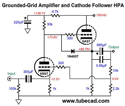
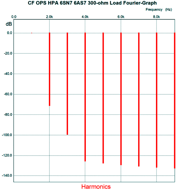
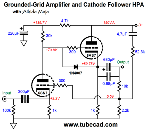
I strove to retain as many of the original parts as possible. The grounded-grid amplifier circuit does not invert the signal's phase at its output. It does, however, present a fairly low input impedance, which explains the addition of the 300µF non-polarized electrolytic capacitor as the input coupling capacitor. The 10k and 2.2k resistors define a negative feedback loop that sets the amplifier's gain to 2 (+6dB). Why so low? The cathode follower output stage can deliver a fairly clean 2Vpk of output voltage swing into 32-ohm headphones, and the iPod and the smart phone top out at about 1Vpk of voltage output. Thus, in an effort to reduce the distortion as much as possible, we need to use as much negative feedback as we can. Increasing the headphone amplifier's gain would necessarily subtract from the potential negative feedback. On the other hand, if 300-ohm headphones are driven, the amplifier's gain rises to 3.4 (10.6dB). Here is what we get with a 300-ohm load, i.e. a huge decrease in distortion.
By the way, when we double the output voltage swing, we quadruple the power output. In other words, this headphone amplifier would put our four times the power of an iPod into 32-ohm headphones and twelve times more power into 300-ohm headphones. Nonetheless, the 6SN7 can only deliver so much gain. In contrast, its cousin octal tube, the 6SL7, with its mu of 70, can deliver far more gain.
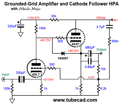
Once again, I tried to retain as many of the original parts as possible. Note that the 2.2k negative feedback resistor has been replaced by a 6.2k resistor, which implies that much more negative feedback is being utilized. With the 6SL7 input tube providing more gain, thus greater fueling the negative feedback, both the distortion and output impedance fall, while the PSRR improves. So far, not bad. What is missing is my signature touch: vastly improved PSRR. What is needed is some Aikido mojo.
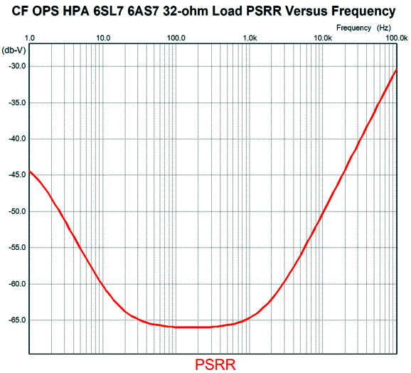
The added 4.7µF capacitor and 300k resistor produce a -30dB improvement in PSRR, making headphone listening far more enjoyable.
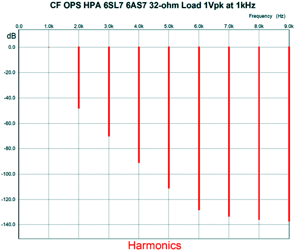
Note how the PSRR-versus-frequency null centers nicely where the ripple resides, 100Hz and 120Hz, depending on your wall voltage frequency. Here is the SPICE-generated Fourier graph.
What if you want to retain the 6SN7 and add the Aikido Mojo?
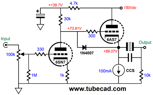
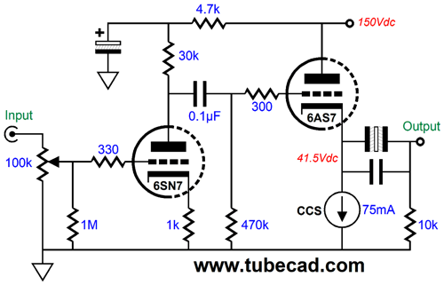
Returning to the original Darkvoice circuit, the modification I would like to make is to add an internal coupling capacitor and a constant-current source.
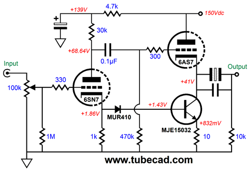
The 6AS7 triode now sees a much larger cathode-to-plate voltage, which will allow more peak current flow. In addition, the constant-current source sees half the voltage-drop compared to the previous circuit. Most importantly, this arrangement allows us to use far better-sounding non-polarized electrolytic capacitors as the output coupling capacitors. Note that no safety diode was needed in this circuit. An LM317 in the T0-220 package would make a fine constant-current source; the current-adjustment resistor value would be 16 ohms. Alternatively, we can get extra fancy and introduce a hint of push-pull operation.
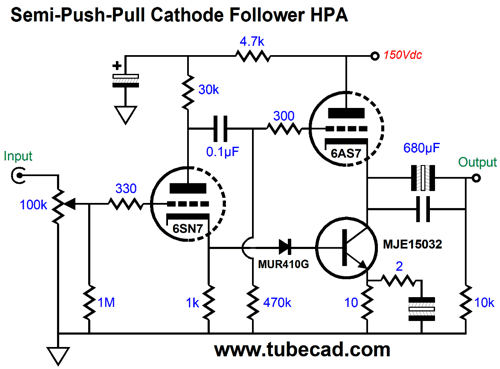
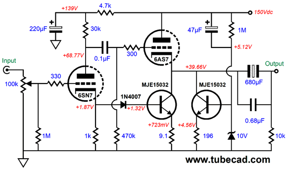
The NPN transistor functions as both a constant-current source and an active push-pull device. How is that possible? Note the transistor's base sees a portion of the input signal present at the 6SN7's cathode. This signal is in phase with the input signal and creates an in-phase current conduction that works with the 6AS7's own anti-phase current conduction, the result being the introduction of some push-pull operation. Why only some? The 6AS7 triode's current swings are far larger than the NPN transistor's. Call it semi push-pull operation. Why bother? Greater output power and lower distortion. If we want a greater amount of push-pull operation, we can add an additional emitter resistor and a terminating capacitor.
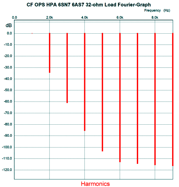
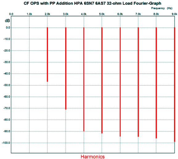
The 10-ohm resistor sets the DC idle current, while the 2-ohm resistor forces more AC push-pull operation. Here is the SPICE-generated Fourier graph for 1Vpk of output into 32 ohms at 1kHz.
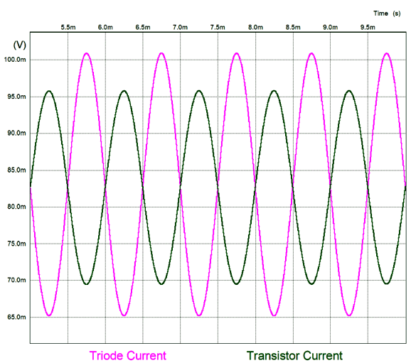
With the added capacitor and resistor, the THD is 0.48%; without them, 1%. Now compare this with the stock amplifier's graph shown earlier. Here are the current relationships between triode and transistor.
As you can see, the triode is undergoing larger current swing. What happens if we forgo the 2-ohm resistor and just shunt the 10-ohm emitter resistor with the 1kµF capacitor? The distortion falls to 0.25%. So why not eliminate the 2-ohm resistor? For most, this would be the preferred setup, but I like the option of being able to vary the ratio of single-ended to push-pull operation. I can even imagine a rotary switch that offered pure single-ended at one extreme and pure push-pull at the other. Bear in mind that pure class-A push-pull sounds far more like pure single-ended than class-AB push-pull does. We can introduce some Aikido mojo by adding an additional NPN transistor.
The NPN transistor on the right nulls the power-supply noise at the output. By the way, in SPICE simulations, I found that shunting the 1N4007 diode with a large-valued capacitor lowered the distortion a tad. Another approach to achieving a push-pull output stage is the following.
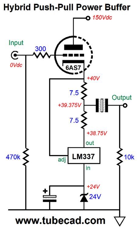
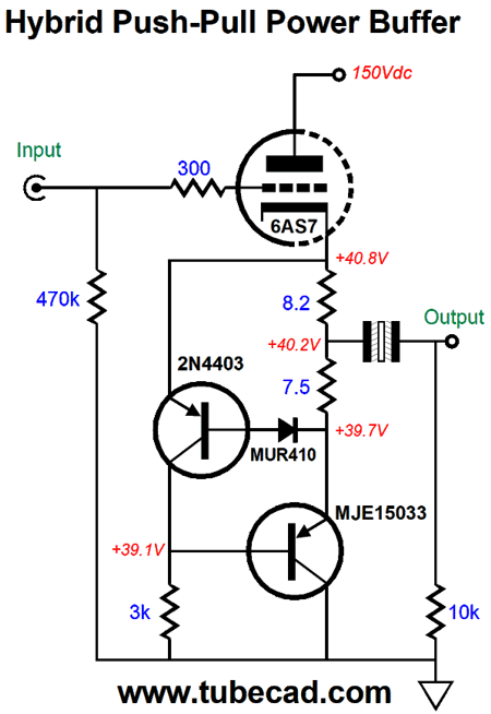
I have shown this topology many times before. You can think of it being either an impedance-multiplier circuit (IMC) or a form of solid-state SRPP, but the result is the same: we can deliver up to twice the idle current into the load and the loads appears to be twice as large to the 6AS7 triode. Unfortunately, they no longer make the LM337-HV, the higher-voltage version of the LM337. Thus, the need for the 24V Zener diode, which limits the voltage window with in which the LM337 operates. We could go further by shunting the LM337 with a 36V Zener. Notice how the LM337 also works to auto bias the 6AS7, much as an LM317 configured as a constant-current source would. Alternatively, we could go the discrete transistor route.
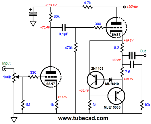
The 2N4403 PNP transistor strives to maintain a fixed voltage drop across the two 7.5-ohm resistors, which it does by controlling the MJE15033's current conduction. Since the MJE15033 can handle far more voltage than the LM337, 250V versus 37V, we can forgo the 24V Zener. By the way, I found in SPICE simulations that the 8.2-ohm resistor worked to balance better the current swings between triode and transistor. Adding this output stage to the entire circuit is no big deal.
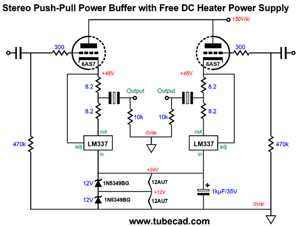
The 6SN7 stage develops a gain of close to 9, while the entire amplifier realizes a gain of 2.7 (+8.6dB) into a 32-ohm load. The THD with 1Vpk of output into 32 ohms was 1% and the PSRR came in at -16.5dB. As I mourned the wasted heat in the version that used an LM337 and 24V Zener, I realized that we were throwing away a free DC power supply voltage of 24Vdc. Let's leave the Darkvoice 336SE behind and use a 12AU7-based cathode-coupled amplifier input stage. In other words, each channel gets one 12AU7 tube. The 12AU7's heater element draws 150mA at 12.6V. Thus, we can place the two heaters in series and place the heater string in parallel with the 24V Zener or, better still, place each heater in parallel with a 12V Zener.
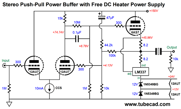
Note how both channels' output stages share the same path to ground through the two heaters in series. The 1kµF capacitor AC bypass the heaters and zeners. As the 6AS7 must first heat up and conduct before the 12AU7s get their heater voltage, the start-up is naturally slow, which will extend the 12AU7 tubes' life span. Okay, let's put it all together. Here is one channel:
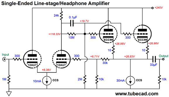
Both 12AU7 triode draw the same 5mA of current at idle and the 100k negative feedback resistor does not provide very much AC negative feedback signal, but it does provide needed DC feedback. The 44.2k resistor and 47µF capacitor are an injection of Aikido mojo that vastly improves the PSRR. Since we have left the Darkvoice 336SE far behind, we can also replace the 6AS7 with a different output tube. I have been getting excellent results from the JJ ECC99 dual triode tube. Here is high-voltage version of the circuit that is meant to double as high-quality line-stage amplifier and 300-ohm headphone amplifier.
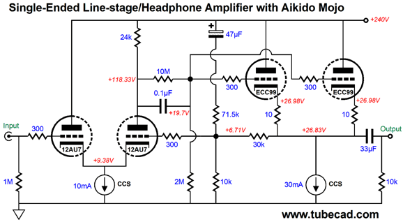
Note the much higher B+ voltage. The ECC99 offers almost twice the transconductance and one third the heater current draw of the 6AS7. What's missing is some Aikido mojo.
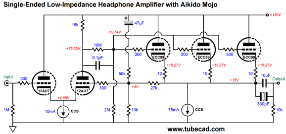
Now, we have improved PSRR and low input capacitance and low distortion and low output impedance. What about 32-ohm headphones? In order to drive such low impedances, we need to lower the B+ voltage and increase the idle current and add an extra triode to the output stage and a much larger coupling capacitor.
With these changes, we can easily get 2Vpk into 32 ohms. By the way, 2Vpk is twice the output voltage that an iPod puts out, but far short of 1W of output. To get 1W into 32 ohms requires a peak voltage swing of 8V. If we replaced the constant-current source with an LM337-based IMC, we could get an easy 4Vpk voltage swings from the three ECC99 triodes, which would translate into 250mW of power into 32 ohms. I happen to think that three tall ECC99 tubes situated behind two short 12AU7 tubes would look great. On the other hand, the more parallel ECC99 tubes we use, the lower the distortion and output impedance and the greater the output power. For example, some ribbon headphones require a crazy high amount of power to sing. Well, if each channel were given three ECC99 output tubes, a total of six triodes, we could actually get 1W into a 32-ohm load. (Or, as the advertising copy would read, 1,000mW!) Imagine two lines of four tubes. I would search auto-part websites for tasteful chrome V8 medallions (badge) with which to adorn the front panel of the headphone amplifier.
Ready for this, I only used about half of the tube circuit I had sketched out for this section. Mercy, but circuits abound. Circuits, circuits everywhere, yet the same handful always appear in my in box.
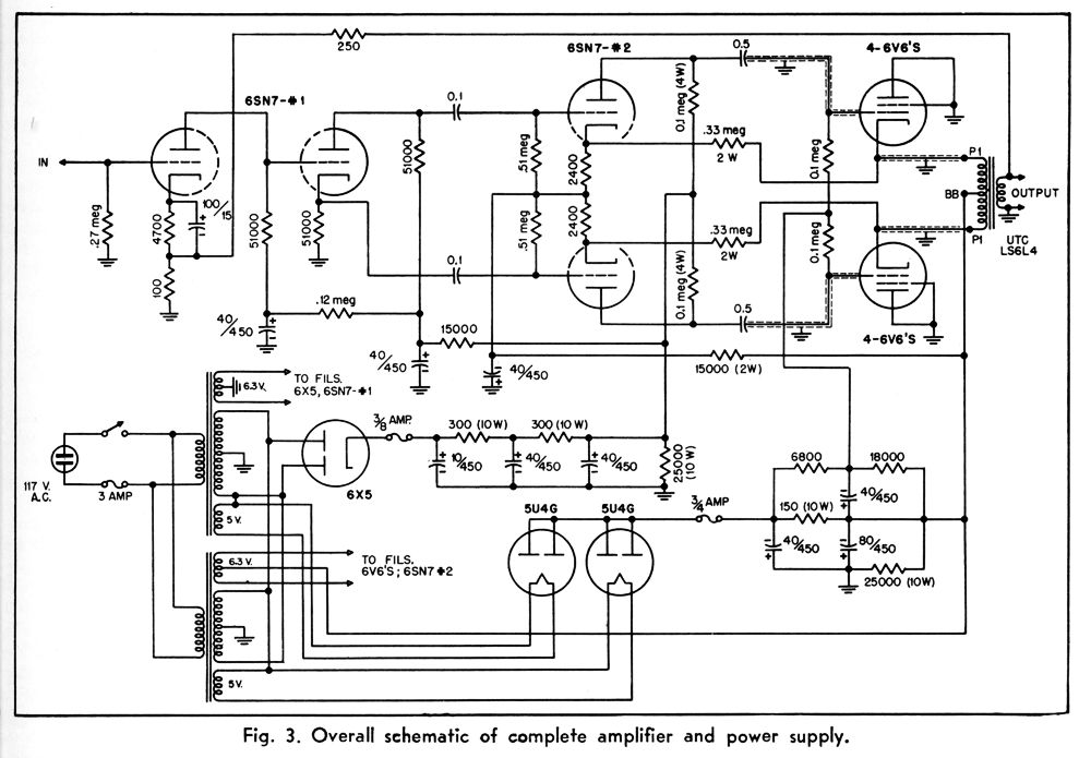
Cathode-Follower Push-Pull Amplifier The push-pull output stage is situated in the bottom half of a bipolar power supply, while the input stage and split-load phase splitter are located in the top half of the power supply, leaving the entire rail-to-rail power supply voltage for the driver stage, which must deliver huge balanced signals to the output tubes.
Needless to say, I would do it differently. In the article's text, we read about motor-boating problems. (They failed to see how the bipolar-power-supply rail's ripple would become a signal.) Nonetheless, it's interesting. Note how the negative rail was created with two 5U4G rectifiers. Also note how two power transformers were used. By the way, the 6SN7 driver stage receives some positive feedback through the 330k resistors. In my view, using positive feedback in a putatively cathode-follower output stage is always an admission of failure, as the positive feedback undoes the degenerative negative feedback. You cannot have your cake and eat it. You must choose.
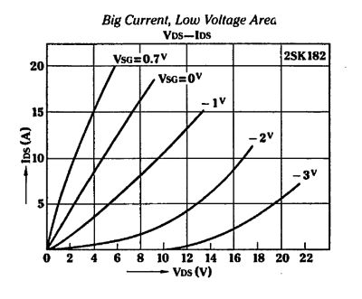
Depletion-Mode MOSFETs
Sure looks like a triode, until you see that the Y-axis is in amperes, not milliamps. A more conventional depletion-mode MOSFET that caught my interest is the IXTH16N10D2, which is a 100V/16A N-channel device in the TO247 package with a wattage rating of 830W. Of course, that rating is made when the device forcibly cooled to 25C. Nonetheless, it is impressive, as it would allow us to build a class-A amplifier with relatively small heatsinks. Mind you, the heatsink would be hot enough to toast bread on it. Here is a unity-gain power buffer based on enhancement-mode MOSFETs that would accept a hot output signal from a tube-based line-stage amplifier. (If you are thinking Moskido, you are on the right track.)
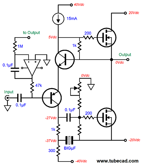
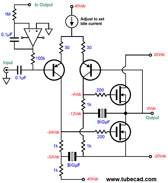
The output devices are plain enhancement-mode MOSFETs. The bastode input stage is effectively a differential amplifier, which compares the output to the input signal. The constant-current source splits its current flow into two branches, 10mA down the bastode transistors and 5mA down the 1k gate at the top. The OpAmp-based DC servo eliminates any DC offset at the output. How it works in this circuit will no doubt cause quite a few heads to be scratched. Let's say the output strays positively, which will prompt the OpAmp output to swing negatively, which in turn forcing greater current conduction from the two bastode transistors, resulting in less current flow through the 1k gate resistor; and, thus, the top MOSFET will see a lower source-to-gate voltage, provoking a lower conduction, bringing the output voltage back in line with ground potential. The potentiometer adjusts the idle current through the output devices. Note the two sets of bipolar power supply rail voltages, +/-20Vdc and +/-40Vdc. Also note that the PNP transistor's collector voltage is -30Vdc, fully -10V below the bottom output MOSFET's source voltage. Why? My desire was for the output stage to make full use of the 40V voltage differential and not bottom out, which would have occurred had only +/-20Vdc bipolar power supply been used. In other words, the PNP transistor would have crashed into its collector resistor. With the secondary and higher power-supply rail voltages, the bastode input stage can follow the input signal and still control both output MOSFETs. All in all, a fun circuit, but totally unsuitable for use with depletion-mode MOSFETs. Or is it?
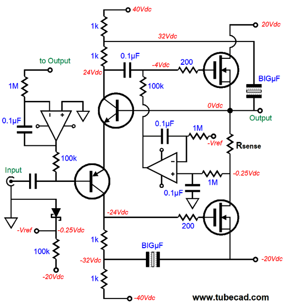
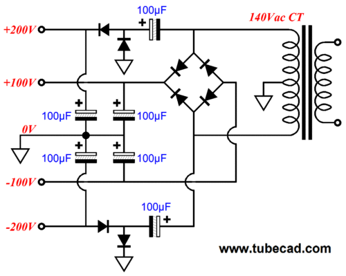
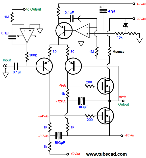
By shifting the internal coupling capacitor from the bottom MOSFET to the top MOSFET, we have no problem driving the depletion-mode MOSFETs. To be frank, I am assuming here that the MOSFETs exhibit fairly high transconductance, say at least 5A/V. If they don’t or if large-valued source resistors are used, then the bastode input stage might crash into the bottom collector resistor, thereby limiting peak negative output voltage swings. Another assumption here is that the output stage will be run in strict class-A push-pull idle current, i.e. at one-half the peak output current. In this example, we would divide 20V by 8 ohms and get 2.5Apk, so we would set the idle current to 1.25A. Because average current flow is constant in a class-A output stage, we can use a DC servo to auto-bias the output MOSFETs. The OpAmp on the right monitors the average voltage drop across the current-sense resistor. If the voltage drop across this resistor exceeds the reference voltage, the OpAmp's output will swing positively, causing the output stage's current conduction to fall. Do not be troubled by the two sets bipolar power-supply rails. A standard power center-tapped transformer can be used. Here is an example from an OTL circuit from post 195. The topology remains the same, but we just use a 30Vac CT transformer instead.
The lower-voltage bipolar power-supply rails are full-wave rectified, while the higher-voltage rails are half-wave rectified, which is not an issue, as they do not deliver much current. For the more traditionally minded, we can use the traditional differential pair. Let's start with output triodes first.
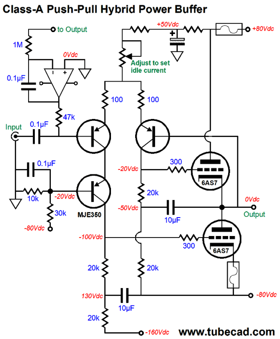
This power buffer offers no signal gain. It is meant to drive low-impedance headphones, which will be driven by a hot tube-based line-stage amplifier. The output tubes run a heavy idle current of 115mA, which implies a peak output current swing of 230mA, which further implies 845mW of power into 32-ohm headphones. The MJE350 serves to establish equal voltage drops across the differential amplifier stage's two transistors. The OpAmp prevents DC offsets. (Nonetheless, I would add a non-polarized electrolytic output coupling capacitor or add a DC window comparator circuit and clamping relay on the output.) The top 10µF capacitor ensures balanced anti-phase current swings from the top and bottom triodes. The bottom 10µF capacitor prevents the -160Vdc power-supply rail's ripple from becoming a signal source. Check out post 323 for another take on this sort of hybrid topology.
Okay, let's now translate this circuit into pure solid-state.
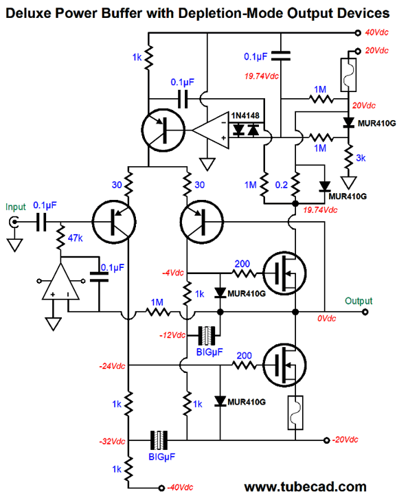
Once again, we make use of the two bipolar power supply voltages, but no internal coupling capacitors are used. (The input coupling capacitor does not count, as it falls outside of the negative feedback loop.) In other words, the two output MOSFETs are DC coupled to the input stage. So how do we set the idle current? We do so through the constant-current source at the top. The higher its current flow, the greater the output stage's current flow. The OpAmp is a DC servo that nulls DC offsets. Once again, this is a power unity-gain buffer, not an amplifier. Thus, the needed signal gain must come from the line-stage amplifier. Unlike the hybrid version, this power buffer can drive loudspeakers. Since tubes have no problem producing big voltage swings, this seems a reasonable compromise: tubes for voltage gain; MOSFETs for current gain. Here is a possible auto-bias circuit for class-A, push-pull operation.
The right OpAmp monitors the average voltage drop across the current-sense resistor and compares it to reference voltage. If the output stage idle current is too high, the OpAmp's inverting input will see a voltage more negative than the reference voltage, which will cause the OpAmp's output to swing up positively, which in turn will reduce the topmost PNP transistor's current flow and, by extension, the output stage's idle current. Note that the reference voltage is created using a Schottky diode (aka a hot-carrier or barrier diode). Also note how the RC low-pass filter terminates into the +40Vdc power-supply rail. This is important, as we are creating effectively a constant-current source out of the topmost PNP transistor. Several nice touches are missing. For example, each MOSFET could get its own gate Zener that would the maximum gate voltage possible. The current-sense resistor, Rsense, could be bypassed by two forward-biased Schottky diodes in series, which would as voltage clamp on the resistor, preventing the auto-bias from being knocked off balance. And, of course, the +/-20Vdc power-supply rails could be and should be fused.
Yes, this version is quite a bit different. What happened? In the time it took me to draw the schematic, I thought of several enhancements to the circuit. (Thirty years ago, there was a popular saying in Silicon Valley, "You cannot hear Broskie's amplifier twice." Why not? I constantly altered it.) Note that the bottom fuse only breaks the connection to the bottom MOSFET's source, leaving the rest of the circuit still powered. This is essential. Had we placed the bottom fuse in the conventional manner, the top MOSFET's current conduction would spike when the bottom fuse opened. Not good. On the other hand, if the top fuse blows, the auto-bias circuit will shut down the constant-current source, resulting in the bottom MOSFET shutting down as well.
Music Recommendation: The Blues
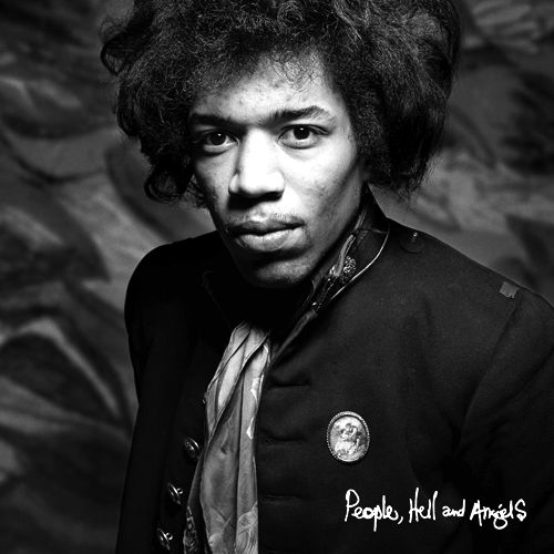
Since a hundred or so albums have appeared after Hendrix's death, I long ago gave up trying to hear them all. I am glad to have listened to this album, however, as the heavy blues influence makes for a more easy listening experience. The blues flavor then led me to Buddy Guy and Junior Wells and their 1991 album, Alone and Acoustic. I have been a huge fan of both blues men since I was a teenager, so I cannot explain how I ever missed hearing this album.
Chicago Blues at its best. In addition, it's a great recording. The next blues album I tracked down at Amazon Music was Chris Whitley's Dirt Floor. Whitley (1960 - 2005) is one of those musicians that I would like more if I didn't know what he looked like. (To this list, I will add Keith Richards.) This album a simple affair, which ideally suits the music. As I play his album, my eyes closed, I can easily imagine he is singing in front of me.
After I had washed my ear clean of Tidal's recommended music with this healthy treatment of the blues, I felt much better. //JRB
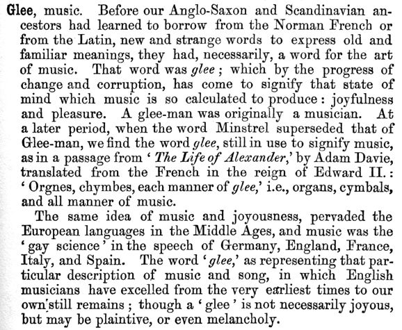
*Glee
I have seen the words "glee-dream" and "gleeharmony" and both refer to the pleasure derived from hearing music. In Johnson's Dictionary, he states:
User Guides for GlassWare Software
For those of you who still have old computers running Windows XP (32-bit) or any other Windows 32-bit OS, I have setup the download availability of my old old standards: Tube CAD, SE Amp CAD, and Audio Gadgets. The downloads are at the GlassWare-Yahoo store and the price is only $9.95 for each program. http://glass-ware.stores.yahoo.net/adsoffromgla.html So many have asked that I had to do it. WARNING: THESE THREE PROGRAMS WILL NOT RUN UNDER VISTA 64-Bit or WINDOWS 7 & 8 or any other 64-bit OS. I do plan on remaking all of these programs into 64-bit versions, but it will be a huge ordeal, as programming requires vast chunks of noise-free time, something very rare with children running about. Ideally, I would love to come out with versions that run on iPads and Android-OS tablets.
|
I know that some readers wish to avoid Patreon, so here is a PayPal donate button instead. Thanks. John Broskie
John Gives
Special Thanks to the Special 83
I am truly stunned and appreciative of their support. In addition I want to thank the following patrons:
All of your support makes a big difference. I would love to arrive at the point where creating my posts was my top priority of the day, not something that I have to steal time from other obligations to do. The more support I get, the higher up these posts move up in deserving attention.
If you have been reading my posts, you know that my lifetime goal is reaching post number one thousand. I have 502 more to go. My second goal is to gather 100 patrons. I have 176 patrons to go. Help me get there.
Only $9.95
The Tube CAD Journal's first companion program, TCJ Filter Design lets you design a filter or crossover (passive, OpAmp or tube) without having to check out thick textbooks from the library and without having to breakout the scientific calculator. This program's goal is to provide a quick and easy display not only of the frequency response, but also of the resistor and capacitor values for a passive and active filters and crossovers. TCJ Filter Design is easy to use, but not lightweight, holding over 60 different filter topologies and up to four filter alignments: While the program's main concern is active filters, solid-state and tube, it also does passive filters. In fact, it can be used to calculate passive crossovers for use with speakers by entering 8 ohms as the terminating resistance. Click on the image below to see the full screen capture.
Tube crossovers are a major part of this program; both buffered and un-buffered tube based filters along with mono-polar and bipolar power supply topologies are covered. Available on a CD-ROM and a downloadable version (4 Megabytes). Download or CD ROM
|
|||


| www.tubecad.com Copyright © 1999-2020 GlassWare All Rights Reserved |