| John Broskie's Guide to Tube Circuit Analysis & Design |
31 March 2020 Post Number 498 (two to go)
It turns out that it is far more difficult to write less, so I can post more often. For example, this post spills over 4,000 words. Stay home. Stay healthy. Listen to more music.
Two-Tube Single-Ended Amplifier Too simple solutions, however, are just as bad as too complicated a solution. For example, in the tall truck story, we would have to let out air from at least four tires, possibly six or more tires. In contrast, a single lit match applied to the truck's gas tank would also dislodge the truck and require much less effort. Too simple a solution, alas. For many tube fanciers, the simplest tube circuits are the best circuits. Less is more, they exclaim. Much like a Hollywood movie star who believes that the more the plastic surgeon cuts away, the handsomer he will look, the hyper-minimalist tube fancier believes that the more parts he leaves out, especially those parts he whose function he does not understand, the better sounding the amplifier would prove. Thus, grid-stopper resistors must go; so, too, stability-inducing capacitors along with any parts whose purpose he fails to comprehend. Ideally, he would just attach a naked 300B to the loudspeaker, thereby removing all the sonically cluttering parts, for no window pane can be as clear as no window pane. We all know the famous dictum: "Everything Should Be Made as Simple as Possible, But Not Simpler." But do we know who said it? Was it Albert Einstein or Louis Zukofsky or Roger Sessions or William of Ockham or some anonymous writer? The website QuoteInvestigator.com concludes, after an impressively exhaustive examination:
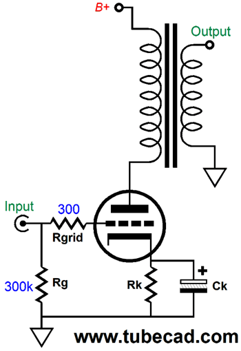
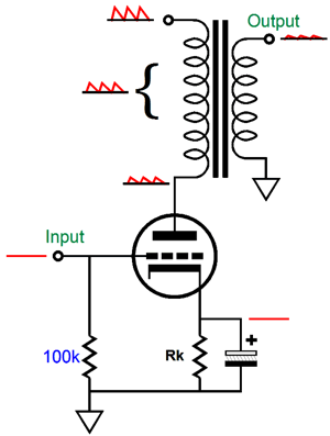
Okay, let's review single-ended amplifiers, extremely simple single-ended amplifiers. Ideally, we could use one output tube, an output transformer, and high-voltage power supply—and little else, say three resistors and one cathode bypass capacitor.
All three resistors are essential. The 300k grid resistor establishes a ground potential DC voltage on the triode's grid. The cathode resistor's voltage drop cathode-biases the triode. The 1k grid-stopper resistor stops something. What does it stop? It stops the triode from oscillating. Why would the triode oscillate? The triode's internal capacitances and its grid's high impedance will interact with any stray inductance attaching to the grid and create an undamped LC network that exhibits a resonant frequency, often at ultra-high frequencies. A subset of Murphy's Law is that any circuit that can oscillate will oscillate. Ideally, the grid stopper resistor must be a non-inductive type, such as carbon-composition or bulk-foil types. The cathode resistor bypass capacitor must be large enough in value to ensure adequate low-frequency bandwidth. A quick formula is Ck = 10,000/Rk where Ck is in µF and low-frequency cutoff frequency is below 20Hz. The output triode would need to be truly amazing, as it must offer a high transconductance (gm) and high amplification factor (mu or µ) and a plate resistance (rp) equal to half the output transformer's primary impedance. For example, with a 3k load impedance, the triode's mu would need to be 450 and its rp be 1.5k and its gm be 300mA/V in order to achieve full output with an input signal of 1Vpk. Such a triode does not exist, and probably could never exist. In other words, we must add an additional triode to the circuit.
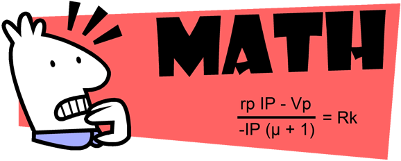
The input stage amplifies the 1Vpk signal sufficiently to drive the output to full power. Assuming a 300B output tube and a primary impedance of 3k, how input signal must the 300B get to deliver the maximum output power? This question raises the following question, what would be the maximum output power? A single-ended amplifier's output stage must be run in strict class-A, so the math seems simple enough. The maximum theoretical power output for a class-A output stage, whether it be push-pull or single-ended, is 50%. A 300B's maximum dissipation is 40W, so the output power is 20W, right? Wrong. If a 3k output transformer is used with an idle current flow of 100mA, the output power would equal Ipk²Rload/2 or, in this example, 15W. Right? Wrong, but closer. A single-ended amplifier's idle current and cathode-to-plate voltage and its plate resistance set the limit to power delivery. Let's assume a B+ voltage of 400Vdc and a voltage drop of 60Vdc across the 300B's cathode resistor, leaving a cathode-to-plate voltage of 340V. Let's further assume an idle current of 100mA (Iq), which is the output transformer's maximum idle current flow. This idle current will give us a cathode resistor value of 60V/.1 or 600 ohms and cathode-resistor bypass capacitor value of at least 17µF, which healthy over design factor of 4, roughly giving us 47µF. Now, we find the peak permissible current flow without incurring positive-grid voltage. Ipk = (Vb – Ik[Rload - Rk - Rdc])/(Rload + rp + Rdc) - Iq where Rdc is the output transformer's primary DC resistance. A 300B's plate resistance is about 660 ohms with a cathode-to-plate voltage of 340V and 100mA. Let's assume an Rdc of 200 ohms (probably too low) for the primary and plug these numbers along with a 3k primary impedance into the formula. The cathode-to-plate voltage drops to 320V; and we get a peak current flow of 60mA, which squared and against 3k/2 equals 5.4W, which is only 36% of our second guess. W = I²Rload/2 In fact, reality will prove less generous, as there are other losses, such as output transformer core loses and transformer's secondary DCR.
Math can prove such a downer that you can readily see why so many audiophiles avoid it. Nonetheless, the sonic difference between 5.4W and 15W is not all that big a deal. Here is a crazy analogy: does the millionaire with $5,400,000 in the bank really live a much more impoverished life than the millionaire with $15,000,000? If this analogy works, it is due to music presenting such a high dynamic range. Strangely enough, the same logarithmic scaling applies to wealth. For example, the richer millionaire doesn't live anything close to a 2.8 times more luxurious a lifestyle; to do so, he would probably need $54,000,000 in the bank. Put differently, a $20,000 bottle of wine does not taste 1000 times better than the $20 bottle. If we take the log of 1,000, we get 3, which is probably how many times tastier the $20k wine would prove. (But then, I am an optimist; others would argue for only 30% or as little as only 8% better tasting, the result of going from 91 points to 99 points.)
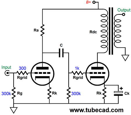
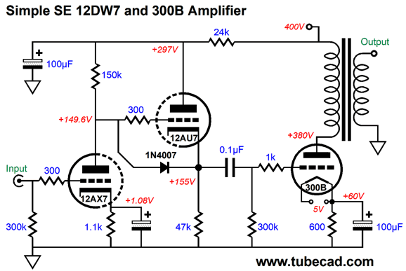
So, how big an input signal is required to drive the output stage to full power? This one is easy. We take the cathode's DC voltage as equaling the peak signal voltage swing. (I could show you the formula for the effective transconductance of a triode with plate load resistance and show how to take the inverse of gm' and multiply it against the peak delta of current conduction to get the require peak grid voltage, but that would be a huge hassle.) If a negative feedback loop were employed, the analysis gets more complicated, as it is easier to turn a triode on than to turn it off. This means the negative half of the input signal should be larger in magnitude than the positive half, which a negative feedback based amplifier would deliver. Okay, we return to the two-tube single-ended amplifier. If we desire an input signal of 1Vpk, the input stage must deliver a gain of 60. A 12AX7 (mu of 100) or a constant-current source loaded 12AT7 (mu of 60) or a pentode could do it. I would use a 12DW7/ECC832, which combines a 12AX7 and 12AU7 triode in one tube envelope. Why? The 12AU7 could be used as a cathode follower, whose low output impedance and higher idle current would extend high-frequency bandwidth and prove faster slewing. In addition, the cathode follower would shield the 12AX7 triode from the 300B's grid resistor's relatively low resistance (300k), thereby increasing its gain.
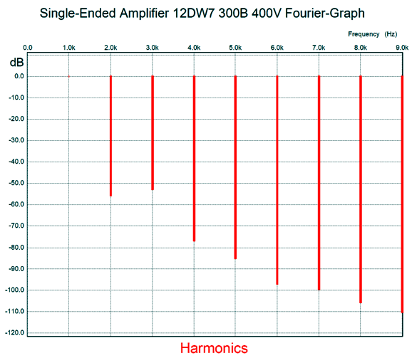
As I see it, this circuit does count as two-tube single-ended amplifier. The next question is how well does this amplifier perform? It achieves full output with a tad less than 1Vpk of input signal. In SPICE simulations, the output impedance was about 1.7 ohms. The high-frequency bandwidth depends too much on the actual output transformer used. The THD came in at 0.039%.
In contrast, the PSRR was weak, only -2dB. The obvious solution is the brute-force, i.e. bigger power-supply capacitors, lots of chokes, possibly a high-voltage regulator. I have nothing against such measures, but I would start with an attempt to figure out how the power-supply noise leaks into the output signal. An analogy would be that before trying to find the best way soak up the water on the kitchen floor—Paper towel? Hand towels? Dry rice? A shop vacuum cleaner?—start by finding what is it that is leaking the water onto the floor and stop the leak. With a single-ended output stage based on a power triode, the leak occurs due to one of the triode's main virtues, its plate resistance. A 300B's plate resistance is about 660 ohms, which is far lower than the primary impedance of 3k. The two placed in series creates a two-resistor voltage divider, with the B+ voltage ripple being the AC voltage that is divided.
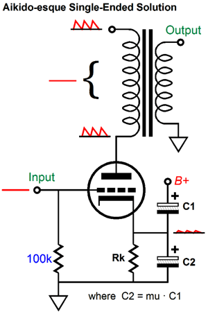
We do the math and find that the primary impedance must see 92% of the AC power-supply noise, hence the weak PSRR. Ideally, the primary would see, paradoxically enough, 100% of the noise at both its ends, which means in the voltage division, the primary would "see" 0% of the noise. Remember that the output transformer is an intrinsically differential device. Apply 1kVac, in phase, to both terminals, and nothing emerges on the secondary. If there is no difference, there's no signal. How do we achieve this goal? The output triode must not alter its current due to the presence of the power-supply noise. How do we make that happen? We add a capacitor, an Aikido mojo capacitor.
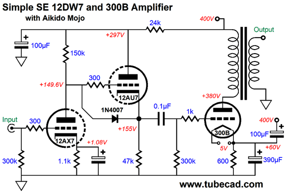
See post 308 for more details. Here is the updated two-tube simple amplifier.
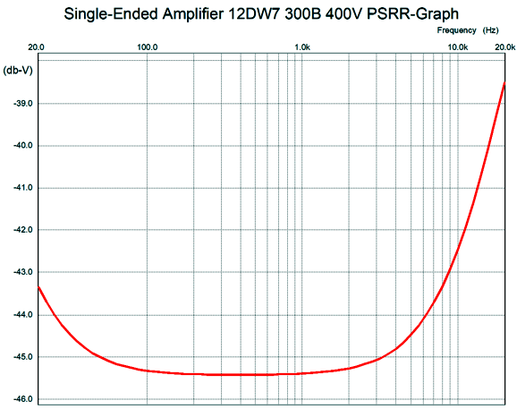
The bottom cathode capacitor must be mu time larger in value than the top capacitor. Since the 300B's mu is 3.9, the bottom capacitor is 390µF, while the top capacitor is 100µF. What this extra capacitor does is inject 1/4.9 as much of the ripple on the B+ voltage to the 300B's cathode. Wait a minute, John, the 300B's mu 3.9, not 4.9. Indeed, but the cathode's effective mu is equal to mu + 1; the plate's mu is 1/mu. Remember that amplification factor is the measure of the relative effectiveness of the grid over the plate in controlling the triode's current conduction. In other words, if we increase the B+ voltage by 3.9V, we can counter the increase in current flow by making the grid more negative by 1 volt. Since a change in cathode voltage is also a change in the cathode-to-plate voltage, the cathode is mu + 1 times more effective than the plate in controlling current flow. Compared to the grid, the cathode is (mu + 1)/mu times more effective. With a 12AX7, the difference is small, as 101/100 is close to 1; in contrast, with a 6AS7, whose mu is 2, the difference is huge, as 3/2 equals 1.5 times more effective. How well did the addition of Aikido mojo work?
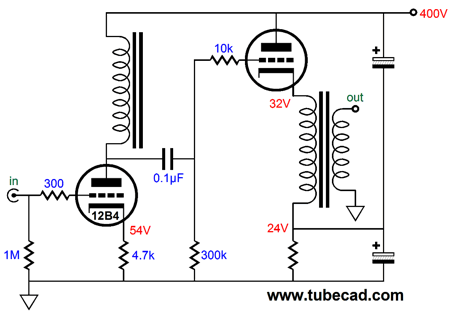
Over 40dB better. Note the critical 100Hz to 120Hz range. By the way, I pointed out this technique 21 years ago here at the Tube CAD Journal. Because so few understand how the added capacitor works, however, seldom does the capacitor appear in single-ended amplifiers. Sad, so very sad. So little the cost, so great the sonic benefit. This $5 capacitor easily beats a $5,000 interconnect upgrade. By the way, this same technique can be applied to cathode-follower output stages.
See post 276 for more details.
Over the decades, I have received emails stating that some tube guru claims that no new tube-circuit development has occurred since 1940; indeed, no further creation is possible, followed by what to I think about that. My answer is always the same: if I were incapable of creating new tube circuits, I would probably believe the same. In fact, I do believe it's impossible—for this tube guru—to create anything new. At the same time, I must admit that La Rochefoucauld was right when he wrote,
Too simple and too complicated would be an example. In short, simple is great, but that doesn't mean that is easy.
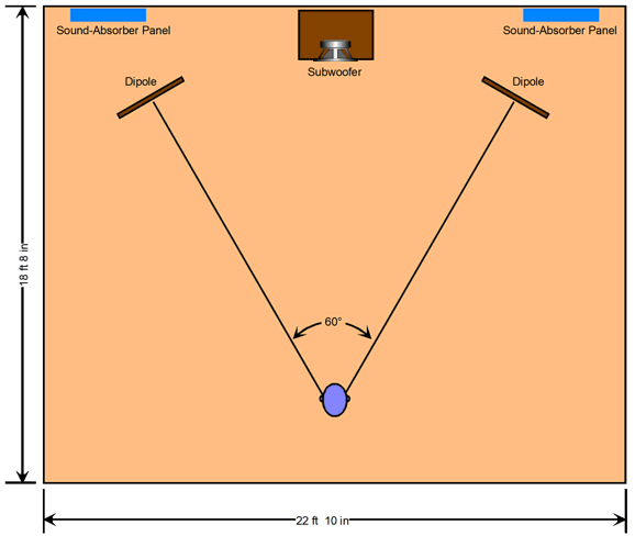
Virtually Large Listening Room I remember reading that, over half a century ago, researchers at RCA (or maybe it was Bell Labs) held listening experiments to discover if listeners could actually be fooled into believing that reproduced sounds were live. Their conclusions, as I remember them, were that three loudspeakers, not two, were needed and that the listener had to be at least 25 feet from the speakers to be fooled. Do you sit 25 feet from your loudspeakers? I don't. Why would such a great distance be needed? My guess is that the wave-front hitting our heads is flat enough when the speaker is that far away. In contrast, when the speaker is eight feet away, the wave-front is rounder, which allows our brain to deduce that we are hearing dual mono, not true stereo. Perhaps this explains why large planer and horn loudspeakers can sound so realistic in terms of soundstage, as wave-fronts they produce are flatter. Compare the horn tweeters width to the dome tweeter's diameter or the two-foot wide planer loudspeaker to a 6-inch woofer. But if you sit 25 feet from your loudspeakers, the dome tweeter's wave-front has had the distance and the time to expand. Let's imagine a good-sized listening room that held large electrostatic or electromagnetic dipole loudspeakers and hefty subwoofer.
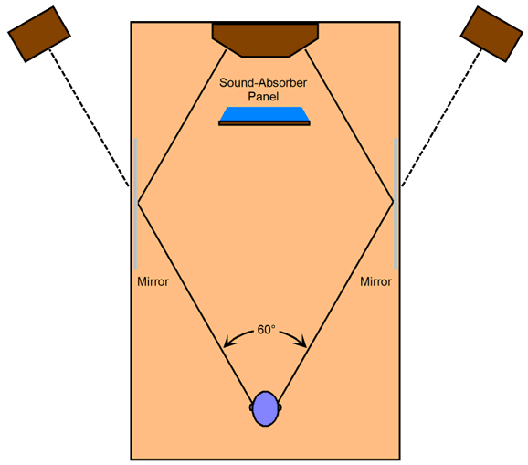
We place the subwoofer far enough behind that its sound time aligns with that from the dipoles. Sound-absorbing panels rest behind the dipoles to dampen the rearward sound emissions. The dipoles and you define an equilateral triangle with 60-degree angles, the theoretical optimum. Now we are ready to do some serious listening. The interesting question is: how can we achieve the same sonic presentation in a far smaller listening room?
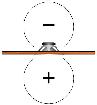
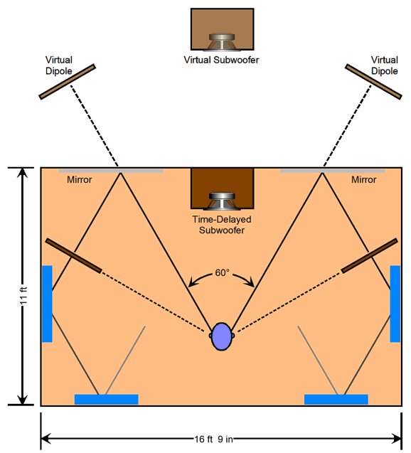
Dipole loudspeakers radiate sound both forwards and backwards, with deep SPL nulls at their sides, the result of the rear radiation being out of phase with the front, causing to two radiations to cancel at the sides. The wider the dipole's width, the deeper the bass it can reproduce. Alas, bass frequencies present huge wavelengths. For example, a 40Hz tone holds a 28-foot long wavelength; 20Hz, 56 feet. In other words, the subwoofer is more of a necessity than an option. Okay, let's get clever. What we need are two more sound-absorbing panels and two tall mirrors.
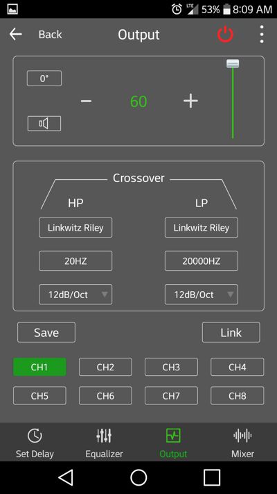
The dipoles are placed so that side's sound null aims at your ears. The mirrors are placed along the front wall so we can see the reflected images of the dipoles. In the mirror's reflection, the dipoles appear to be the same distance from your ears as they did in the much larger room. The same amount of time is required for the sound to leave the dipoles and arrive to your ears as it did in the bigger room. In addition, the same 60-degree angle between the reflected dipoles and your head obtains. Effectively, the loudspeaker are located behind your front wall. Sneaky, no? The subwoofer's output must be time delayed so that its waves time align with the reflected dipole sound. In days past, implementing a time delay would be a pain, as the bucket-brigade-capacitance time-delay chips produced terrible comb-filter aberrations in the frequency response. (Mind you, with frequencies below 100Hz, this was less of a problem.) In contrast, today for $150, you can buy a DSP device that will not only delay the subwoofer's signal for up to 8mS, but will perform the low-pass crossover function. A delay of 8ms equals about nine feet of sound travel. In other words, the subwoofer would seem to be located nine feet behind where it actually is. The DSP device is controlled either with a PC program or with a phone app through a Bluetooth 4.0 dongle, which costs $28.
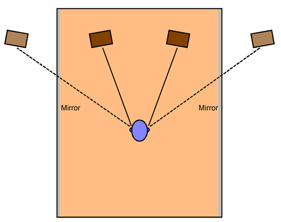
The added sound-absorbing panels catch the dipole's rear radiation hitting the rear wall. In this arrangement, the rear-wall reflections largely miss your ears. The tall mirrors do not have to be mirrors, as plate glass would also work, as would any other hard, brittle surface. What if you don't own or don't want to own dipole loudspeakers? Conventional box loudspeakers can be used, but they do not offer the side sound nulls. In addition, most enclosures are relatively tiny compared the bass wavelengths, so the deep bass leaves the speaker in an omnidirectional fashion. (This is what causes the low-frequency diffraction loss, where the mids and highs are louder than lower midrange and bass.) The workaround might be to limit the loudspeaker low-frequency bandwidth and use two subwoofers, one for each channel. For example, if the crossover were 400Hz, and if the loudspeaker cabinet is large enough, much of the omnidirectional radiation would be lessened. Each subwoofer could sit in front of the mirror, resting on the floor. In fact, it would be fun to build loudspeaker with this arrangement in mind, as we could use the same woofers in the main speakers and in the subwoofers, thus helping to ensure similar frequency response and phasing. Okay, now that we are mentally warmed up, we can entertain the following possible design that uses a single truncated triangular speaker enclosure. Two mirrors are placed against the side walls. In front of the speaker, we place a large sound-proofing panel to prevent any direct radiation hitting our ears.
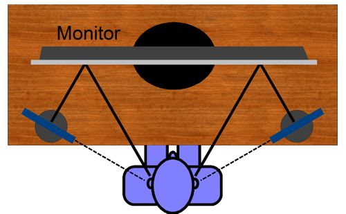
If a subwoofer is used, we can forgo the time delay and place it below the main loudspeaker cabinet. How would it sound? I don't know, but I would love to hear it. Perhaps, this design might even achieve spouse-acceptance. Okay, what if we placed in front of the large sound-proofing panel a big flat-screen TV. This might make a great stereo setup that doubles as a great home theater setup. How did I start down this path? My eyes age. I long for a larger computer monitor. But if I bought one of those huge monitors, I worried about my dipole planar computer speakers getting in the way. Actually, I don't game or watch movies on my PC, so I would simply buy another 27-inch computer monitor, and the two would effectively take up a total of 48 inches, leaving no room for my loudspeakers. As I gazed at my reflection in the monitor, it just hit me that if I placed the dipoles with their sides facings me, I wouldn't hear them until the sound hit the computer monitors and bounced back to my ears, creating the illusion that they were far in front of me and wide apart.
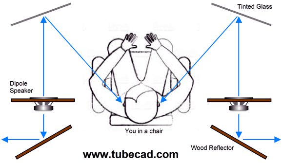
Only one computer monitor is shown, but you get the idea. I also use a subwoofer that holds four 5-inch woofers and rests on the floor, so no time delay would be needed. Actually, the more I think about it, this wasn't the first time I thought of using reflecting dipoles. I like headphones—a lot. At the same time I readily acknowledge that they are a pain in many ways; for example, wires, discomfort, not being able to hear the doorbell or phone. Thus, I have long thought about how to create some sound producing device that was situated half way between headphones and loudspeakers. Forty years ago, my cousin and I experimented with near-field listening, where small loudspeakers stood just feet away from your ears. If you have never tried it, you definitely should, as the result can prove amazing. At the same time, I don't like my field of view obscured. The idea I sketched out was to use electrostatic dipoles and clear-glass reflecting panels.
The image is from post 460, which I posted one year ago. Thus, you can see that this idea has been haunting me for a long time now. Speaking of mirrors, imagine that your listening room's side walls and ceiling were entirely covered with mirror. As you sit and listen, you would see reflections of your loudspeakers. Where you see the speakers, you should place a sound-diffusing panel large enough to obscure the images. Note that I didn't say sound-absorbing panels, as they do not work as well. But as a quick experiment place large sofa cushions or upright bean bags or leafy and large potted plants against the walls were you would see the reflections. Now, listen to your system. Depending on your room, the result can be a substantial improvement in stereo imaging. Sound-diffusing panels work even better. The difficult part is treating your ceiling.
Before our basement was finished, I reveled in great imaging, as I had created a listening room by building a false wall out of bookshelves. I then lined the opposing wall with bookshelves. On all book cases, I purposely staggered the books so an irregular surface was achieved. I didn't have to treat the ceiling, as it was made up of long horizontal 15-inch tall planks of wood nailed upright to the floor above and spaced 18 inches apart. The result was that my loudspeakers could not directly reflect to my ears from the ceiling, as the sound kept encountering the upright planks, forcing the sound either up into the space between planks or back towards the speakers. On the basement floor rested a large, thick wool carpet. The imaging was stellar. Finished, the room is much smaller and the ceiling reflects like mad and only one side wall is book covered. The imaging suffered a big hit, alas.
Music Recommendation: America Again
by Lara Downes
Looking through the new classical albums arrayed at Tidal, I spotted her single, Sometimes I Feel Like a Motherless Child. I had rediscovered her. I landed on her 2016 Album, America Again, which is a collection of classical pieces composed by Americans that were all inspired by either blues or jazz (or spirituals). Once I hit "Play," I had to hear the entire album. (By the way, the title wasn't lifted from a red baseball cap, but from a poem [1935], Let America Be America Again, by the black American poet, Langston Hughes. In fact, it wasn't the bad orange man, but the bad gray man, John Kerry, who had used the poem's title as his campaign slogan in 2004. Surely you remember the outcry, the anguished denouncements of Kerry's obvious jingoism and xenophobic nationalism? "Troubling," Worrisome," remember the adjectives in the press each day? Remember the gray caps emblazoned with LABAA that provoked nightmares in the exceedingly sensitive? Had I owned pearls, I would have definitely clutched them. The fact that Kerry's wife was an immigrant didn't buy him any slack, but then why should it have, for what can be more nationalistic than marrying a foreigner?) The recording is excellent and her playing is distinctly American: bold, enthusiastic, cheerful. Tidal offers 11 other albums by Lara Downes.
//JRB
User Guides for GlassWare Software
For those of you who still have old computers running Windows XP (32-bit) or any other Windows 32-bit OS, I have setup the download availability of my old old standards: Tube CAD, SE Amp CAD, and Audio Gadgets. The downloads are at the GlassWare-Yahoo store and the price is only $9.95 for each program. http://glass-ware.stores.yahoo.net/adsoffromgla.html So many have asked that I had to do it. WARNING: THESE THREE PROGRAMS WILL NOT RUN UNDER VISTA 64-Bit or WINDOWS 7 & 8 or any other 64-bit OS. I do plan on remaking all of these programs into 64-bit versions, but it will be a huge ordeal, as programming requires vast chunks of noise-free time, something very rare with children running about. Ideally, I would love to come out with versions that run on iPads and Android-OS tablets.
|
I know that some readers wish to avoid Patreon, so here is a PayPal donate button instead. Thanks. John Broskie
John Gives
Special Thanks to the Special 84
I am truly stunned and appreciative of their support. In addition I want to thank the following patrons:
All of your support makes a big difference. I would love to arrive at the point where creating my posts was my top priority of the day, not something that I have to steal time from other obligations to do. The more support I get, the higher up these posts move up in deserving attention.
If you have been reading my posts, you know that my lifetime goal is reaching post number one thousand. I have 502 more to go. My second goal is to gather 100 patrons. I have 176 patrons to go. Help me get there.
Only $9.95
The Tube CAD Journal's first companion program, TCJ Filter Design lets you design a filter or crossover (passive, OpAmp or tube) without having to check out thick textbooks from the library and without having to breakout the scientific calculator. This program's goal is to provide a quick and easy display not only of the frequency response, but also of the resistor and capacitor values for a passive and active filters and crossovers. TCJ Filter Design is easy to use, but not lightweight, holding over 60 different filter topologies and up to four filter alignments: While the program's main concern is active filters, solid-state and tube, it also does passive filters. In fact, it can be used to calculate passive crossovers for use with speakers by entering 8 ohms as the terminating resistance. Click on the image below to see the full screen capture.
Tube crossovers are a major part of this program; both buffered and un-buffered tube based filters along with mono-polar and bipolar power supply topologies are covered. Available on a CD-ROM and a downloadable version (4 Megabytes). Download or CD ROM
|
|||


| www.tubecad.com Copyright © 1999-2020 GlassWare All Rights Reserved |