| John Broskie's Guide to Tube Circuit Analysis & Design |
31 December 2013
Happy New Year! I thought that I just might reach blog number 300 this year, but alas, no. Just twenty-four more to go. Perhaps next year. I wonder if I can hit blog number 1,000 before dying. If I keep them short, maybe.
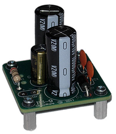
PS-9 Back in Stock
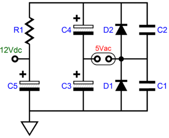
The solution that I have used many times is to use the following circuit to turn the 5Vac winding, which wasn't used to power a rectifier, into a 12Vdc power supply for the input tube's heater.
Of course, a 6.3Vac winding can used as well, which would create 16Vdc of raw DC voltage, which resistor R1 can drop down to 12.6Vdc. A 12AT7, 12AU7, and 12AX7 hold heaters that draw 150mA at 12.6V, which isn't that much current compared to the 2A that a 5AR4 or 5R4 rectifier draws, and it is much less than the 3A that a 5U4 draws. In other words, the 5Vac/2A winding can power a 12A_7 tube easily. What is the current limit? Since the rectifier circuit is a voltage doubler, we must halve the 2A rating down to 1A; then, we must divide by 1.8, leaving us with 0.55A. A 5Vac/3A winding would deliver up to 0.83A. The only hard part is selecting the right value for resistor R1. I first measure the raw DC voltage developed (usually about 13Vdc), then I figure what value would create a 1V voltage drop at 150mA; in this example, 6.8 ohms; but as they don't sell 6.8-ohm 1W resistors, I try a 6.7-ohm resistor. (I always run my heaters a tad low, so a 12.6V tube will get 12V; a 6.3V, 6V. Why? The tube will last longer and often sound better.) I have made these circuits so many times that I can almost solder one together with my eyes closed. Almost. But I much prefer having a PCB to hold the parts together, which is why I created the PS-9 PCB.
Last time the PS-9 was available, I pretty much them sold at my cost, just so I could have some for myself. Well, they sold out quickly (music amplifier shops discovered them) and I ended up fewer for myself than I expected. A small mistake, which I don't plan on repeating. The PS-9 is available now at the Yahoo-GlassWare store.
Single-Ended Power Amplifier PSRR Enhancement A triode's current conduction can be altered in many ways: turn on or off the heater's power supply, change either the plate voltage or grid voltage or cathode voltage. An increase in plate voltage will prompt an increase in current conduction, as well an increase in grid voltage; in contrast, an increase in cathode voltage will force a decrease in current conduction. We can view a triode's plate as having a mu (an amplification factor) of 1, while the grid's mu is equal to the triode's publish mu, which means that the grid is mu-times more effective in altering the triode's current flow than its plate. The cathode is slightly more effective than the grid, presenting a mu equal to -(mu + 1). The negative sign let's us know that the the cathode works in opposition to the grid and plate.
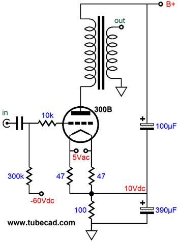
Thus, if we wish to maintain a fixed triode current conduction in the face of power-supply ripple, we must counter the signal at the plate, i.e. the power-supply ripple, by either applying -1/mu of power-supply ripple at the grid or 1/(mu + 1) of power-supply ripple at the cathode. Since the grid receives the input signal and it would be a pain to invert the ripple's phase, we are left with the cathode as our only choice. If we choose capacitor C1's & C2's values carefully, we can assure a fixed current flow through the triode, which means that the output transformer's primary never experiences a power-supply-ripple-induced current variation, which in turn means that the primary never sees a ripple-induced signal to relay to the secondary, ensuring a clean output signal. So what happens if we don't want to use cathode-bias, preferring fixed bias? How do we inject a portion of power-supply ripple into a grounded cathode? Simply, we don't—we can't, as the cathode is grounded. The workaround is to use a small-valued cathode resistor and fixed bias, as shown below.
The 100-ohm cathode resistor only sees a 10V voltage drop, which adds to the -60Vdc grid voltage creating a total of -70Vdc of bias voltage. The 390µF and 100µF capacitors create an AC voltage divider that injects 1/(mu + 1) of the power-supply ripple voltage into the cathode.
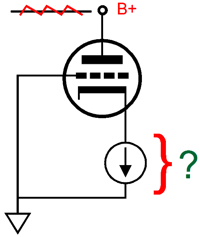
What if we wish to use a cathode-follower output stage, do we need to undo the power-supply ripple's noise contribution? Indeed, is there a power-supply ripple's noise contribution? And if so, how do we proceed? Cathode followers are not perfect and they do relay a portion of the power-supply ripple at their outputs. How much leaks out depends on the triode used and the cathode load impedance. The worst case is when the cathode follower is loaded by a constant-current source, paradoxically enough.
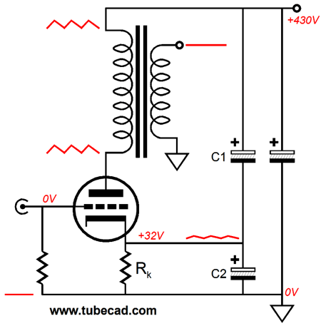
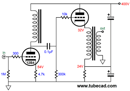
Unlike a grounded-cathode amplifier that exhibits its best PSRR when loaded at its plate by a constant-current source, a cathode follower spills out its poorest PSRR with an infinitely-high load impedance, as the ripple at the plate will appear 1/(mu +1) a large at the cathode. Assuming that the driver stage presents a noise-free signal to the grid of the cathode follower, we can overcome the ripple at the plate by injecting the sampling of power-supply noise at the bottom of the output transformer primary.
In the above schematic we see the same two-capacitor AC voltage divider and the added cathode resistor, which combined with the primary's DCR creates the needed resistance to cathode-bias the output tube. (This added cathode resistor could be replaced by a constant-current source, thereby adding an auto-bias feature.) The 12B4's plate is loaded by an inductor, which will allow its plate to swing far above the 400V B+ voltage, which is exactly what is needed, as the cathode-follower output stage requires huge input signal swings.
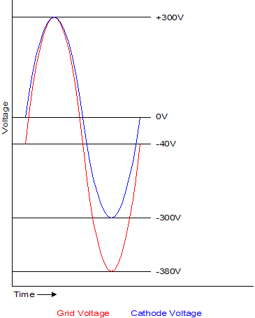
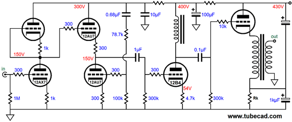
The above graph was lifted from blog number 148, which along with blog number 149 and number 150 are worth reading, as they cover cathode-follower output stages. I mention this because the 12B4's plate cannot actually swing +/-340Vpk, as its cathode resistor will displace a big chunk of the B+ voltage, leaving less for the triode to work with. The 12B4 itself will require a huge input signal, something like +/-60Vpk. The following is a complete amplifier.
Of course, other input and driver stages could be used; and the output tube, output transformer, and additional cathode resistor's value are not specified. Why not? The whole idea is to show what is possible, not what is demanded or expected. I have a lot more that I wished to share, but if I am going to make it to blog number 1,000, I will have to keep them short ;)
Next Time
//JRB |
I know that some readers wish to avoid Patreon, so here is a PayPal button instead. Thanks.
John Broskie
And
High-quality, double-sided, extra thick, 2-oz traces, plated-through holes, dual sets of resistor pads and pads for two coupling capacitors. Stereo and mono, octal and 9-pin printed circuit boards available.
Designed by John Broskie & Made in USA Aikido PCBs for as little as $24 http://glass-ware.stores.yahoo.net/
The Tube CAD Journal's first companion program, TCJ Filter Design lets you design a filter or crossover (passive, OpAmp or tube) without having to check out thick textbooks from the library and without having to breakout the scientific calculator. This program's goal is to provide a quick and easy display not only of the frequency response, but also of the resistor and capacitor values for a passive and active filters and crossovers. TCJ Filter Design is easy to use, but not lightweight, holding over 60 different filter topologies and up to four filter alignments: While the program's main concern is active filters, solid-state and tube, it also does passive filters. In fact, it can be used to calculate passive crossovers for use with speakers by entering 8 ohms as the terminating resistance. Click on the image below to see the full screen capture.
Tube crossovers are a major part of this program; both buffered and un-buffered tube based filters along with mono-polar and bipolar power supply topologies are covered. Available on a CD-ROM and a downloadable version (4 Megabytes). |
||


| www.tubecad.com Copyright © 1999-2013 GlassWare All Rights Reserved |