| John Broskie's Guide to Tube Circuit Analysis & Design |
| 27 September 2014 Parafeed-Amplifier Design
Parafeed Amplifiers
A parafeed power amplifier sidesteps the problem of poor PSRR that most single-ended amplifiers exhibit. What problem? A problem is created out of the triode's virtue: its low plate resistance.
"One is punished most for one's virtues," Friedrich Nietzsche informed us long ago and he was, as is so often the case, right. The triode, unlike the pentode or transistor or MOSFET, offers a wonderfully low plate resistance, which works as an intrinsic negative feedback loop. But in a single-ended power amplifier, the low plate resistance in series with the primary impedance defines a two-resistor voltage divider. And since the plate resistance is usually quite a bit lower than the reflected primary impedance, the majority of the power-supply ripple appears across the primary, which in turn is relayed to the secondary and then to your speakers. If there is a delta, then there is a signal. Over 15 years ago, in the second issue of the Tube CAD Journal, I wrote an article titled, Lowering the SE Amp's Output Noise, which explained how to sidestep the poor PSRR.
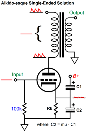
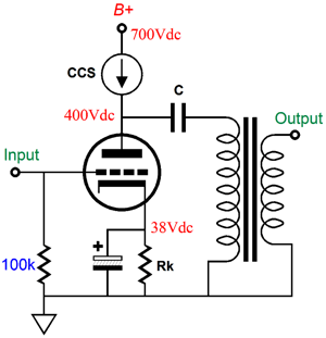
My solution was to inject a small portion of the ripple into the cathode, which ensured that the same amount of ripple that appeared on the B+ connection appeared on the plate, so the transformer saw no delta, no difference, hence no output signal at the speakers. This is the sneaky way to do it. (Perhaps too sneaky or too subtle, as after 20 years of explaining it to many tube-loving solder slingers only few understand how it works.) The brute force way is to employ many chokes and huge power-supply capacitors or high-voltage regulators, so no ripple appears at the B+ connection. Good luck with that. I contrast, the parafeed topology keeps the inductor (choke), but forgoes the shunting capacitor to ground, relying on the inductors high inductance to shield the triode's plate and the output transformer's primary from the ripple. In addition, the output transformer no longer sees a sustained DC current flow, so it no longer needs an air-gap. Indeed, we can use special core materials that offer better performance but which are easily saturated by any DC current flow. Before we break out the bottle of Champagne, bear in mind that the inductor must be of the highest quality, as it will function as a constant-current source of sorts, which will see huge plate-voltage swings and at high frequencies, not just 120Hz that a lowly power-supply choke would see. Speaking of constant-current sources, we could replace the inductor with a constant-current source—if we are willing to pay the high price of a much higher B+ voltage.
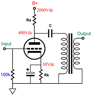
Assuming an idle current flow of 100mA and a 3k primary impedance, the maximum peak voltage swings that the plate can undergo is ±300V, as 100mA against 3k ohms equals 300V. Thus, at least +700Vdc is needed for the B+ voltage. Or, if we do not trust active constant-current sources, we could use a very-large-valued load resistor.
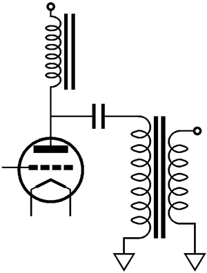
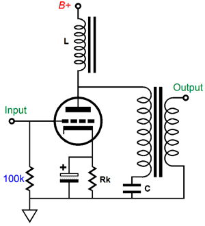
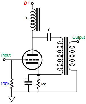
Yes, this is a bit silly, but it does make a point: the bigger the resistor value, the less ripple appears at the plate. Now that we know how a parafeed amplifier works, we can look into how it is implemented. The capacitor that couples the output transformer to the triode's plate must be large enough to allow low-frequency bandwidth down to 20Hz or so. The formula is an easy one: C = 159155/(rp + Rload)/Frequency, where C is in µF and rp is the plate resistance. For example, with an rp of 400 ohms and primary impedance of 3k and 20Hz cutoff, C should be at least 2.4µF big in value. (Surprisingly small, don't you think?) Speaking of this internal coupling capacitor, it can be moved to the other end of the primary, as shown below.
Does this make any difference? Sonically, I doubt it. In terms of safety, I prefer the original setup up, as any short between primary winding and the case would be far less dangerous. On the other hand, if there is anything to polarized interconnects, which I certainly believe there is, perhaps having the primary charged up to the B+ voltage is a good idea. More testing is required. Another popular arrangement is the following one, redolent of the Ultra-Path setup. Many argue that this arrangement is the purer path, as it no longer places the icky bypass capacitor in the signal path. Yeah, sure.
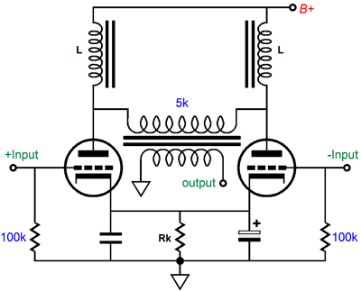
Before we move on to the interesting stuff, I must point out that you can make a push-pull parafeed amplifier, which will require two inductors and two output tubes.
Once again, no DC current flows through the output transformer, so no air-gap is needed within the transformer. One rule that must be observed is that our amplifier never depart from honest-to-God class-A operation. Just like the single-ended version, the inductor must never be expected to give up more than twice the idle current. Note that the primary impedance of 5k, which must be roughly twice of what we would use in a single-ended version. Why? Effectively, each output tube sees a load equal to half the primary impedance. The result is that we get twice the power output over the comparable single-ended version, as we effective have two identical single-ended amplifiers working in anti-phase, pushing and pulling to twice the output power. In addition, we get an even better PSRR, as what little ripple leaks past the two inductors will equal each other on both sides of the primary, so the equally leaked noise falls out of the equation. No delta, no signal. Moreover, the shared cathode resistor, which makes matched tubes a strict requirement, will see equal but out-of-phase current swings, which add up to unity. In other words, because of the strict class-A operation, the cathode resistor sees a nearly DC current flow, which means that the bypass capacitors, with no AC signals to contend with, have much less work to do as well. Why not not just use the conventonal push-pull arragement instead? A good question. One answer is that we could use plate-to-cathode feedback more readily.
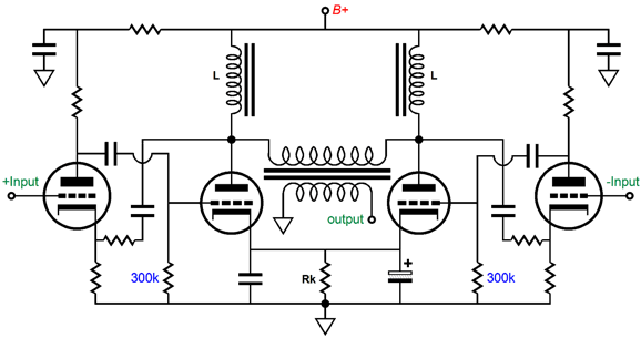
Without the B+ ripple, the two negative feedback loops have a much easier time of keeping thier output tube in line.
Parafeed and Plate Feedback
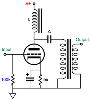
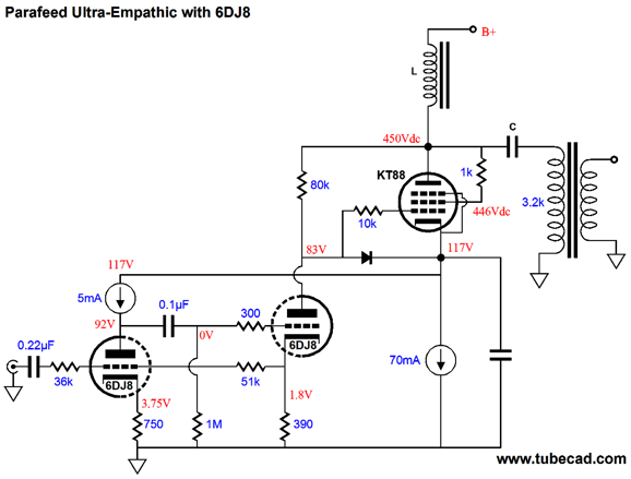
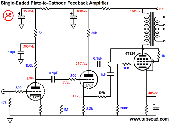
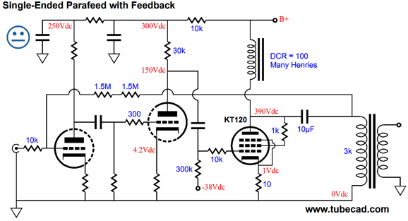
In the above schematic, we see an Ultra-Empathic power amplifier that uses a parafeed inductor and coupling capacitor to attach the output transformer to the plate. We could just as easily—indeed, more easily—make a partial-feedback design. But before we move on, let's look into why normal plate-to-cathode feedback is a bust in a tube amplifier.
Why the sad face, when this seems to be such a good design? Yes, it does look appealing, as the negative feedback from the KT120's plate to the 12AU7's cathode seems to promise low distortion, lower output impedance, and better PSRR. And it does deliver all of these—except the last feature: better PSRR. In fact, it produces a worse PSRR. 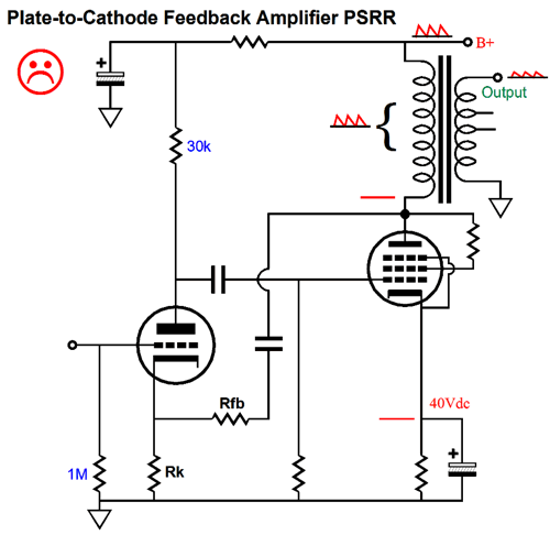
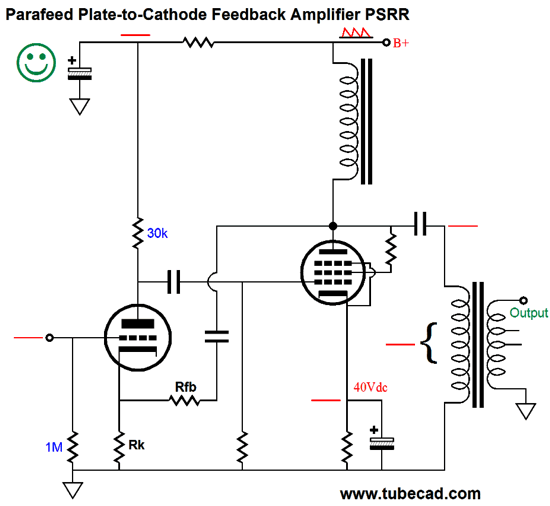
Imagine that the negative feedback loop proves so effective that no power-supply ripple appears at the plate. Great! Well, no, not so great, as the output transformer now sees 100% of the ripple across its primary, which means that the speaker sees the ripple divided by the output transformer's winding ratio. Now, compare the above circuit to the one below.
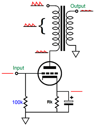
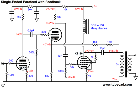
Note how the inductor and the negative feedback loop work to eliminate any power-supply ripple on the plate of the output tube, and in turn from appearing across the output transformer primary. Once again, no delta, no signal. Okay, since we got the green-smiley-face seal of approval, how do we flesh-out this design into a working power amplifier? One possibility is to attach the feedback loop on the other side of the internal coupling capacitor.
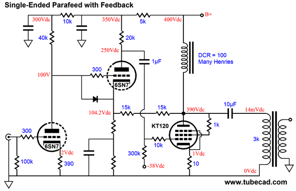
Or, we can attach the feedback loop to the plate, as shown below.
Note that the driver-stage 6SN7 triode DC couples with the input stage and a protective diode is in place to save the 6SN7 from excessively high grid-to-cathode voltages at turn on. Also note how one of the driver stage's cathode resistors is shunted by a bypass capacitor. I have yet to fiddle with this circuit in SPICE simulations, so I do not know what the optimal resistor values are yet. our goal would be to get full output (about 15W) from the amplifier with an input signal of 1Vpk. By adjusting the two cathode resistor values, we can achieve our goal—if we have enough open-loop gain that is. We might need more gain to feed the feedback. In that case, a 6SL7 or other high-mu triode could be used as the input tube. I would use a CCDA stage or an Aikido amplifier stage and then try to get as much negative feedback going as I could. Normally, such a desire is fraught with problems, as high-feedback amplifiers tend to be squirrelly, goosey things that break into instability with little prompting. This design, with its two gain stages and only one reactive device, should be much more stable. For those fearless types, who have never seen a circuit too complex or too daunting, the following might work out well.
The feedback loop now encompasses the input tube and the three coupling capacitors. In theory, this arrangement will yield the lowest distortion. It just might, but the three coupling capacitors make me nervous. If your goal is feedback stability, do not throw a bunch of phase-shifting reactive devices into the loop. Thus, no green-smiley-face seal of approval. At least not yet.
Next Time
For those of you who still have old computers running Windows XP (32-bit) or any other Windows 32-bit OS, I have setup the download availability of my old old standards: Tube CAD, SE Amp CAD, and Audio Gadgets. The downloads are at the GlassWare-Yahoo store and the price is only $9.95 for each program. http://glass-ware.stores.yahoo.net/adsoffromgla.html So many have asked that I had to do it. WARNING: THESE THREE PROGRAMS WILL NOT RUN UNDER VISTA 64-Bit or WINDOWS 7 & 8 or any other 64-bit OS. I do plan on remaking all of these programs into 64-bit versions, but it will be a huge ordeal, as programming requires vast chunks of noise-free time, something very rare with children running about. Ideally, I would love to come out with versions that run on iPads and Android-OS tablets.
//JRB |
I know that some readers wish to avoid Patreon, so here is a PayPal button instead. Thanks. John Broskie
Kit User Guide PDFs
E-mail from GlassWare Customers
High-quality, double-sided, extra thick, 2-oz traces, plated-through holes, dual sets of resistor pads and pads for two coupling capacitors. Stereo and mono, octal and 9-pin printed circuit boards available.  Aikido PCBs for as little as $24 http://glass-ware.stores.yahoo.net/
Support the Tube CAD Journal & get an extremely powerful push-pull tube-amplifier simulator for TCJ Push-Pull Calculator
TCJ PPC Version 2 Improvements Rebuilt simulation engine *User definable
Download or CD ROM For more information, please visit our Web site : To purchase, please visit our Yahoo Store: |
|||


| www.tubecad.com Copyright © 1999-2014 GlassWare All Rights Reserved |