| John Broskie's Guide to Tube Circuit Analysis & Design |
05 April 2020 Post Number 499 (One to Go to 500)
Stuff
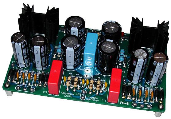
Recently, I had a rude discovery. I had soldered together a PS-8 power supply for a customer and I was ready to test it. My Variac was ready and I had attached my test leads to the first of two heater regulators. I wore my reading glasses, which hold plastic lenses, just in case a capacitor exploded or vented. Why not safety glasses? They were in the garage. As I slowly upped the AC voltage, everything looked good. But once I hit the target AC 120Vac, the regulator's output voltage continued to climb, reaching 13Vdc, one volt too high. I then tested the second heater regulator; it, too, was 1V too high. Dang it. I discharged the capacitors removed the regulator resistors. They measured exactly. I checked each solder joint with my ten-power jeweler's eyepiece. I ran a sharp toothpick between solder pads. Nothing changed; the voltage was 1V too high, which it also was i the second heater regulator. The only faulty device could be the three-pin adjustable voltage regulator, LD1084, an LDO design that can pass 5A. I searched the web to see if others had the same problem; nothing, well at least not yet. My soul-crushing fear was that since I had sent out about 80 of these IC regulators in kits, I might have to replace all 80. (About half of my sales are outside of the USA, so the postage alone would have killed me. Recently, I had to pay $37.45 to ship $10 worth of capacitors to Europe.) Perhaps it was due to ESP, but I turned my focus to the voltage meter, a relatively new device. My gaze filled with malice, seeing the voltage meter as a traitor of sorts. I know it sounds as insane as thinking the weight scale in the bathroom must be wrong, as you couldn't possibly weigh that much. Still, I was convinced that the VOM was at fault. I needed proof, however. I dug out my 30 year-old VOM, not as fancy as the new VOM, but beloved; made in Taiwan, not China; a birthday present from my brother. All the voltages were on the mark. I then tested a fresh AA battery, also perfect. Actually, I had recently tested dead batteries with the new VOM and the batteries didn't measure all that dead, yet they failed to light LEDs. No doubt this clue remained submerged in my mind. We always make assumptions, but we seldom question them. A mistake. I used to know a fellow who worked in Silicon Valley, and his job was making sure all test equipment was accurate. He pestered me with his kind offers to go through my test gear, ensuring that they could be traced back to the Weights and Measures Division. (At the time, I owned a bunch of equipment, most of it old HP equipment. I feared it would take a day to go through it all.) I always declined his offers, as I always checked gear when I first acquired it—I owned 0.01% resistors and 1% capacitors and 1% inductors just for this purpose—and I assumed that the equipment that passed once couldn't drift off spec. I was wrong.
Bipole-Dipole Loudspeaker
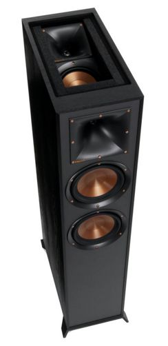
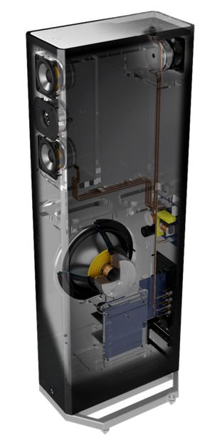
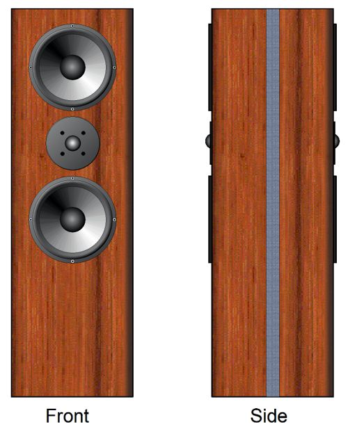
This is not what I had in mind; instead, I was thinking of a loudspeaker cabinet that held, working in phase, front and rear firing drivers. An example is the Definitive Technology BP9020.
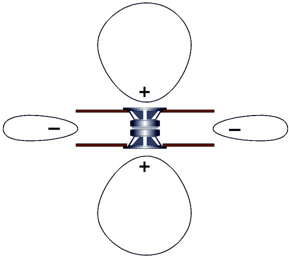
The BP9020's three front drivers are arranged in the D' Appolito setup (MTM), where the tweeter sits between two woofers. A rear driver creates the bipole sound dispersion. The BP9020 also holds a built-in powered subwoofer. This sort of bipole only exhibits the bipolar-sound radiation at high-frequencies, as the low-frequencies radiate in an omnidirectional fashion, because the speaker enclosure is tiny compared to the low-frequency wavelengths. What if this was not the case? What if the low-frequency radiation was also bipolar, with SPL nulls at the side, like a dipole speaker? In other words, it would function like a dipole in terms of radiation patterns, but with in-phase rear radiation. Is that possible? Well, we could place to dipole speakers together, so that that both radiated in phase.
As the negative sound leaves in between the panels, it encounters the front and rear positive sound radiation. What we are likely to get is four side nulls, not two. If we do not use an electrostatic or electromagnetic flat panel loudspeaker, but conventional cone woofers and midranges and a dome tweeter, we could allow only the woofers to side vent. This would go further to creating a bipole loudspeaker, as the mids and high-frequencies are quite directional. Additionally, we could use sound-absorbing material at the enclosures sides, which would further limit the mids from escaping from the sides.
This sort of speaker enclosure actually has a name, aperiodic loading. Aperiodic enclosures fall somewhere between acoustic suspension and bass reflex enclosures. I happen to dislike bass reflex loudspeakers, as the thrill of bumpy bass soon fades. Acoustic suspension loudspeakers are often over stuffed and sound like it, thick and slow. My favorite type of enclosure is the transmission-line, but they big and heavy. To my ear, the Aperiodic enclosure is the best compromise for a smallish loudspeaker. They do, however, require tuning.
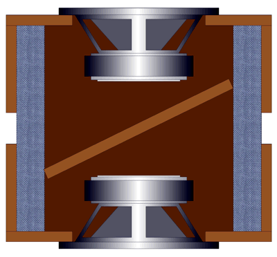
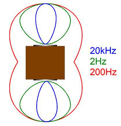
The way I have done this is to moisten one side of a shiny metal sequin and adhere it to the woofer cone. Then I shine a laser beam on the sequin, so the reflected beam hits the wall or ceiling. The dancing trace of red light functions as an enormous oscilloscope. I then tap a 1.5V battery across the woofer terminals, thereby creating a steep pulse. Ideally, the woofer should respond to the pulse in a critically damped fashion. Critically damped is neither over damped nor under damped; its zeta (damping ratio) should equal 1. This is what most designed mechanical systems aim for, for example, turntables, car suspensions, automatic door opener… In other words, the light dot should trace a big bounce up, then a soft but fast decline to neutral. If the trace creates a sinewave that slowly attenuates away, the woofer is under damped and requires more stuffing in the opening. If the trace climbs up but does not attain the full height and then slowly falls away, the woofer is over damped and some stuffing should be removed. One big advantage to such a speaker design, with front and rear firing woofers, is that the in-phase woofer movements cancel, preventing the enclosure from rocking. Imagine you are standing on a skateboard and you fire a shotgun straight ahead of you, you will travel backwards. But if you could somehow manage to fire two shotguns, one firing backwards and one forwards at the exact same moment, you would rest in place, as the two opposite and equal reactions would cancel. My hope is that with the sides of the enclosure holding long open gaps, and with the correct amount of stuffing in the gaps, the side output of negative-phase bass will be close to entirely cancelled by the front and rear sound radiation. Here is what I want the polar response graph to look like.
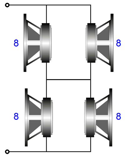
The speakers do not have to cover the entire audio bandwidth, as we could limit their low-frequency bandwidth to 100Hz and then fill in the missing bass with a subwoofer. Speaking of crossovers, with four woofer/fullrange drivers, getting the desired 8-ohm impedance is easy: just use four 8-ohm drivers and configure them in series-parallel.
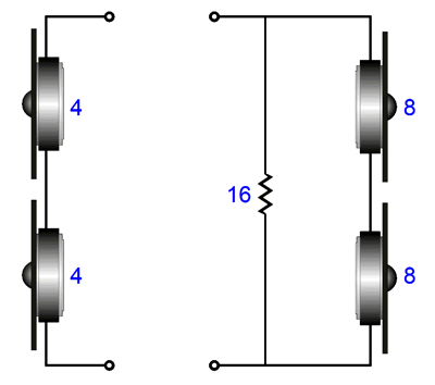
Since each driver sees half of the output voltage from the amplifier, its SPL will be reduced by half (-6dB), but as the front and rear have twice the radiating surface of a single driver, the two drivers output sum back to unity (0dB). In other words, whether we stand in front or behind the loudspeaker, the SPL will be the same as single driver. Making an 8-ohm load out of two 4-ohm tweeters is easy, as we just place them in series. If two 8-ohm tweeters are used, then their SPL per one watt must be 6dB higher than the woofer's. We place the 8-ohm tweeters in series and then shunt this 16-ohm load with a 16-ohm resistor, bringing the combined impedance down to 8 ohms.
By the way, this loudspeaker does not have to be used with any mirrors or reflecting tricks. Indeed, it probably would sound fabulous in a conventional setup. Why? During the 1990s, studies (in Canada, I believe) found that our ears want the reflected sounds to be time delayed by more than 3 milliseconds and to offer the same frequency content as the direct sound emitting from the loudspeaker. All dipoles and omnidirectional loudspeakers do this intrinsically. Tiny mini monitors come close, due to their small cabinets. Big loudspeakers, with only front-firing drivers, do not.
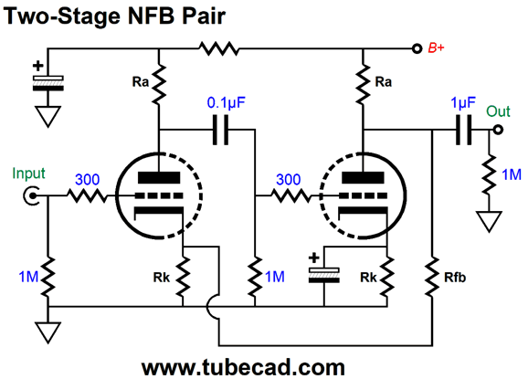
Two-Stage Negative-Feedback Pairs
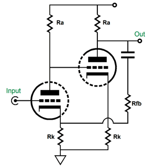
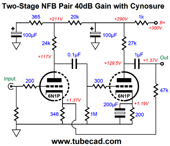
The output signal returns to the input triode's cathode through the feedback resistor, where the signal attenuates due to the two-resistor voltage divider formed by the feedback and cathode resistors. The greater the attenuation, the larger the output signal will be, as the input triode's cathode becomes the gain stage's inverting input. Two internal coupling capacitors are shown, one for the output signal and one for the negative feedback loop. If the gain is set to a high enough level, and if the output triode draws enough current, we can directly couple the negative feedback resistor to the output triode's plate.
Let's take this topology and flesh out the part values.
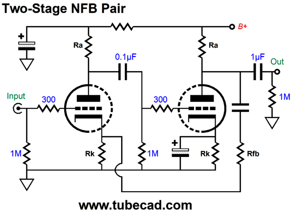
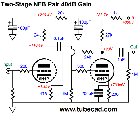
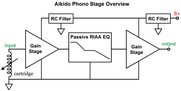
Note that the input triode draws close to 4mA, but its cathode resistor sees a current flow of 7.6mA, as the DC coupled feedback resistor draws 3.7mA. Without the feedback resistor, the cathode resistor value would need to be about 350 ohms. The 6N1P twin-triode tube can prove extremely quiet, which is why I used it in this example of a high-gain amplifier stage. Its gain is 1:100 (+40dB) and it would make an excellent microphone preamp or the first stage of a two-stage phono preamp with passive RIAA equalization in between stages.
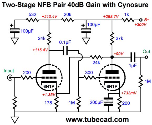
In SPICE simulations, the THD was vanishingly low, as in better than 0.01% with 100mV of peak output at 1kHz, climbing to 0.03% at 1Vpk of output; and the distortion was almost entirely 2nd harmonic. The amplifier's PSRR was good at -62dB at 100Hz. If we add one of my signature Aikido mojo resistors, the cynosure resistor, the PSRR improves to -98dB at 100Hz.
The cynosure resistor purposely leaks a small portion of the power-supply noise into the input triode's output, which the second grounded-cathode amplifier will then amplify, but in an inverted fashion, so the two opposing noise signals cancel. Returning to the negative feedback resistor, we can terminate it on the other side of the output coupling capacitor, but this means that the output will hold the same DC voltage as the input triode's cathode.
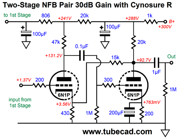
The over 1V of DC offset looks as if it must be a huge liability, but it can prove an asset in certain circuits. For example, in a two-gain-stage phono preamp, with passive RIAA equalization, the DC offset will be passed unattenuated to the second gain stage's input. Say 2Vdc appears at the input, the input triode can absorb the 2V DC offset by using a larger-valued cathode resistor, which in turn will allow us to use a lower valued negative feedback resistor. Why would that be an advantage? We might need less gain and still like to DC couple the negative feedback resistor to the plate. For example, say the first gain stage offered 40dB of gain, then we lose 20dB due to the passive RIAA equalization network, resulting in 20dB, so we only need 20dB to 30dB of extra gain. Here is an example of a second feedback gain stage with a gain of 30dB.
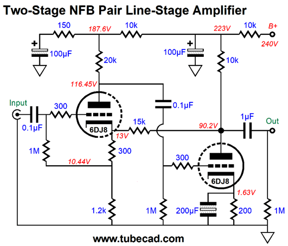
Another audio use that requires less gain is the line-stage amplifier. My own prejudice is that a gain of 4 (12dB) is optimal, but the seeming standard is a gain of 10 (20dB). I have seen 30dB tube line-stage amplifiers—in fat, I have built one—which strikes me as crazy, far too much gain. The following design uses a 6DJ8 and delivers a gain of 10 (20dB).
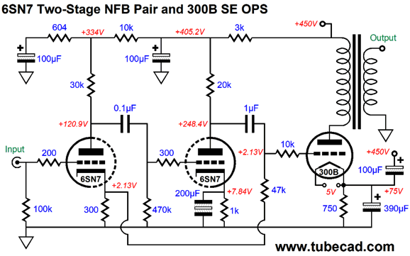
The 15k negative feedback resistor terminates into the input triode's cathode and its signal then attenuates by 10.5 fold, so only 0.095V of the output voltage swing of 1V appears at the cathode. If OpAmps were used, we would expect a gain of 11, but the triodes do not deliver anything near the same open-loop gain as the OpAmp. In fact, this circuits' open-loop gain is only 203 (46dB) in SPICE simulations, which means the line-stage amplifier uses 26dB of negative feedback. Okay, why not use the input coupling capacitor to terminate the negative feedback resistor to the second triode's plate? We could, but the internal coupling capacitor would have to be huge, as the 15k feedback resistor would have to be replaced by a 3k resistor, which would certainly drag down the output triode's output, as the feedback resistor would become a low-impedance load. Remember that this amplifier configuration is basically a current-feedback design, as the inverting input (the input triode's cathode) presents a low impedance, unlike its grid, which presents a staggeringly high impedance. In addition, with three capacitors inside the negative feedback loop, things can go squirrelly fast. Even with the one coupling capacitor between the two triodes, the second stage cathode-resistor bypass capacitor becomes an issue, as too large a value can lead to a bass hump. But by placing the extra coupling capacitor at the input, outside the negative feedback loop, we have much less to worry about. Another application of the two-stage negative-feedback pair—either with the feedback resistor directly terminating into the second triode's plate or into output side of the output coupling capacitor—is in a single-ended power amplifier. The lower the amplification factor (mu) of the output triode, the more gain will be needed to drive it to full output. Here is an example that uses a 6SN7 and 300B output tube.
The 6SN7-based two-stage pair delivers a total gain of 80, so 1Vpk of input signal is enough to drive the 300B to full output. Note the Aikido mojo technique on the 300B's cathode, where the two capacitors vastly improve the output stage's PSRR. Also note that the 300B is being run hot, as it would dissipate 37.5W. In reality, the output transformer's DCR would eat about 30V of the B+ voltage, reducing the dissipation to 34.5W. See post 425 for more details on the two-triode NFB pair.
Music Recommendation: Leyla McCalla (Now, I am simply not a video-kinda guy, as I cannot bear the low information flow. For example, we might read an essay in five to ten minutes, but the same informational content could easily take an hour or two to watch in a documentary. In contrast, music, podcasts, and audio-books allow us to attend to them while still doing other things.) In spite of my prejudice against videos, I watched a few of Downes' videos. One stood out, where she was joined by Leyla McCalla, who sang and played cello. Dang, I fell in love with her singing. Tidal offers two of her albums, The Capitali$t Blues and A Day for the Hunter, A Day for the Prey. Both are worth listening to, but hard to categorize in terms of genre. I have seen her labeled as a Cajun singer, which sort of works. Wikipedia says, "McCalla is an American classical and folk musician." I am tempted to place her more in the jazz genre category.
Here is the biography offered by Tidal:
Amazon shows at least four other of her albums. Let's hope that Tidal catches up.
//JRB
User Guides for GlassWare Software
For those of you who still have old computers running Windows XP (32-bit) or any other Windows 32-bit OS, I have setup the download availability of my old old standards: Tube CAD, SE Amp CAD, and Audio Gadgets. The downloads are at the GlassWare-Yahoo store and the price is only $9.95 for each program. http://glass-ware.stores.yahoo.net/adsoffromgla.html So many have asked that I had to do it. WARNING: THESE THREE PROGRAMS WILL NOT RUN UNDER VISTA 64-Bit or WINDOWS 7 & 8 or any other 64-bit OS. I do plan on remaking all of these programs into 64-bit versions, but it will be a huge ordeal, as programming requires vast chunks of noise-free time, something very rare with children running about. Ideally, I would love to come out with versions that run on iPads and Android-OS tablets.
|
I know that some readers wish to avoid Patreon, so here is a PayPal button instead. Thanks. John Broskie
John Gives
Special Thanks to the Special 84
I am truly stunned and appreciative of their support. In addition I want to thank the following patrons:
All of your support makes a big difference. I would love to arrive at the point where creating my posts was my top priority of the day, not something that I have to steal time from other obligations to do. The more support I get, the higher up these posts move up in deserving attention.
If you have been reading my posts, you know that my lifetime goal is reaching post number one thousand. I have 504 more to go. My second goal was to gather 1,000 patrons. Well, that no longer seems possible to me, so I will shoot for a mighty 100 instead. Thus, I have 16 patrons to go. Help me get there.
Support the Tube CAD Journal & get an extremely powerful push-pull tube-amplifier simulator for TCJ Push-Pull Calculator
TCJ PPC Version 2 Improvements Rebuilt simulation engine *User definable
Download or CD ROM For more information, please visit our Web site : To purchase, please visit our Yahoo Store: |
|||


| www.tubecad.com Copyright © 1999-2020 GlassWare All Rights Reserved |