| John Broskie's Guide to Tube Circuit Analysis & Design |
|
Odds 'N Ends
A Challenge
I was informed by a reader that this was, in fact, impossible, that the output could never become the input of a non-inverting amplifier, at least not with the diamond circuit. Well, we have to be extra careful with things impossible, as they come in so many different flavors. Some things deemed impossible are merely unlikely, such as anyone buying a lotto ticket actually winning the big prize. In my own case, it would be impossible to have won, as I have never—ever—bought a lotto ticket. Other things are considered impossible only because they are difficult, such as balancing three billiard balls atop each other, which although extremely difficult, is not strictly impossible.
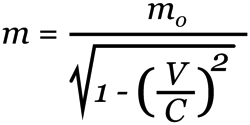
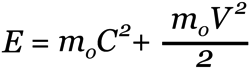
Some things are theoretically impossible, such as moving one of the billiard balls faster than the speed of light. Why is that theoretically impossible? As a subluminal moving object approaches the speed of light, its mass increases, and as the mass increases, more energy is needed to further increase its speed. The formula for Einstein's velocity-dependent mass is as follows:
where m is the resulting mass, mo the rest mass, V the velocity, C the speed of light. If the object is at rest, then the two masses, m and mo, equal each other. But as the objects' speed approaches the speed of light, the rest mass gets divided by an ever decreasing number, which results in an ever increasing mass. Soon enough, due its exponential growth in mass, there would not be sufficient energy in the universe to accelerate the ball's near infinite mass.* Even closer to being truly impossible are things logically impossible, such as having an all-powerful cannon ball and an insurmountable wall in the same universe, as either one precludes the other one's existence; if the ball is all powerful, then there can be no insurmountable walls; and if the wall is truly insurmountable, all-powerful cannon balls cannot exist. Well, where does the alleged impossibility of making a non-inverting amplifier out of the diamond topology fit on this range of impossibility? I put it way over at the only somewhat difficult end of the spectrum. Here is why.
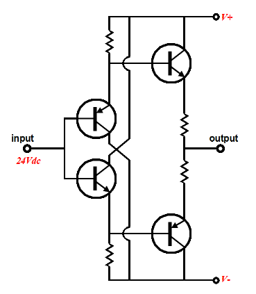
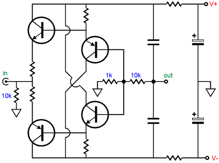
A positive input voltage prompts the output to swing positively; indeed, to swing about ten times more positively than the input voltage, as the 1k and 10 feedback resistors set the gain of this non-inverting amplifier. Here is another non-impossible variation.
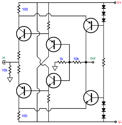
Once again, we get non-inverting amplification. A positive input voltage serves to decrease the bottom input transistor's conduction, but increase top input transistor's conduction, which in turn cause the top output transistor to conduct more, while the bottom output transistor conducts less, thereby pulling the output voltage up positively. Now, that wasn't nearly as impossible as it might have seemed at first. As Henry Ford famously said, "I am looking for a lot of people who have an infinite capacity to not know what can't be done." Then there is the slogan of the US Armed Forces: the difficult we do immediately; the impossible takes a little longer.
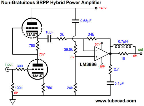
New SRPP Hybrid Amplifier
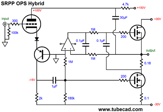
But rather than fight the tide of desire for an SRPP-based hybrid amplifier, I have decided to go with the flow—for a change. But not quite, as I have inverted the order, with the SRPP stage coming at the end, not the input of the amplifier. You want an SRPP hybrid power amplifier, well here it is.
The two power MOSFETs (IRFP240 types) are configured as a class-A, push-pull output stage. The bottom MOSFET receives the input signal produced by the triode and transistor bastode topology. The top MOSFET then senses the current flow through the speaker and develops an anti-phase current conduction as a response. The wee small 0.18-ohm sense resistor between MOSFETs develops all the AC signal the top MOSFET needs to vary its conduction in anti-phase to the bottom MOSFET. And the 0.1µF capacitor relays that tiny AC signal (along with the big output swings) to the top MOSFET's gate. The DC servo-loop is made up from the OpAmp and the two 1M resistors and the 0.1µF capacitor. Its job is to eliminate any DC offset at the output. If the output strays from 0V for any prolong period, the OpAmp applies a correcting output voltage. The 1M resistor in series with the 180k resistor set the DC bias voltage for the bottom MOSFET. The bigger the bottom resistor is in value, the greater the current flow through the two MOSFETs. The 30µF capacitor is interesting, as it serves an interesting purpose in this amplifier, one that few solder-slingers will spot. Can you? What does this capacitor do in this circuit. Yes, it partially shields the triode from the power-supply noise present at the B+ connection. But if that were its sole aim, why isn't it grounded, rather than terminating at the output? Okay, enough stalling. The capacitor completes a negative feedback loop with the triode. Imagine that you quickly attached a battery to ground and the amplifier's output, so a positive pulse would travel up through the capacitor to the triode's plate, causing the triode to conduct a tad bit more current. How much more current? By Vpulse/rp amount. For example, with a 3V pulse and an rp of 3k, an increase of 1mA would be added to the triode's idle current, which would then travel through the 2k resistor, creating a 2V positive pulse at the bottom MOSFET's gate, which in turn would prompt about a 10A increase in the bottom MOSFET's conduction, which would pull the amplifier's output down. Moreover, the top MOSFET would cease to conduct altogether. In other words, a 3V disturbance prompted effectively a 20A counter response, so the output impedance would equal 3V/20A, or 0.15 ohms. Okay, let's n0w start at the input. A +1Vpk input signal will cause the triode's current conduction to rise by roughly its transconductance against the 1V signal, which will case the 2k resistor to see a big increase in its voltage differential, which will become the bottom MOSFET's input signal. Thus, the amplifier's output will swing down. But at the same time, so will the triode's plate voltage, which will undermine the positive grid voltage. The result is that the triode's amplification factor (its mu) will set the signal gain for this amplifier. This obtains for the simple reason that the triode's mu is a measure of its grid's effectiveness in controlling current flow through the triode relative to its plate. So, a mu of 33 means that a +1V increase in grid voltage can be countered by a -33V decrease in plate voltage.
More Ultra-Empathic Circuits
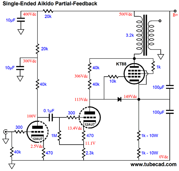
Well, the plate impedance is given by this equation: Z = rp + (mu + 1)Rk where rp is the plate resistance and Rk is the cathode resistor value. The problem is that making Rk bigger in value undermines the gain (the triode's transconductance) and the larger resistor displaces more precious voltage. Well, what if we give up on the 100% goal and settle for something partial? One consequence is that we can no longer just apply the ultra-path capacitor from output tube cathode to B+ connection. But if we get clever, we can still apply some of that old Aikido black magic.
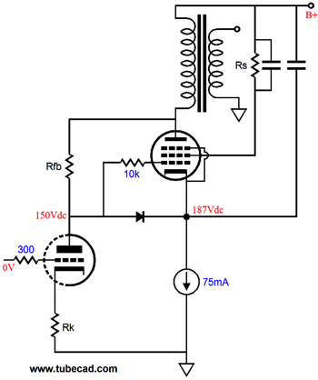
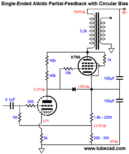
A 12AU7 is used for both input and driver triodes. But no feedback extends from the input triode to the driver triode, so we end up with partial feedback. In other words, we don't really have a voltage-to-current converter here, just two cascading grounded-cathode amplifiers. I set the two shunting capacitors to the same value (100µF) and then fiddled with the values of the driver stage to get a null in power-supply noise at the speaker terminals. Note that the constant-current source of the previous designs has been replaced by two big resistors in series. Why? Since we have given up on 100% feedback in this design, the CCS is not as important as it had been. (Besides, I felt like going retro.) As soon as I had finished drawing the above schematic, my mind thought of how a circular-bias method could be added.
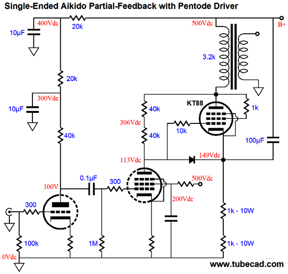
If the output tube draws too much current, the voltage drop across the 200-ohm resistor will increase and, in turn, increase the 12AU7's conduction, which will pull down its plate voltage, which will decrease the output tube's current flow. A nice circle of DC negative feedback. Ziggy, of Hi-End Audio.com, pointed out that if a high plate impedance was the driver stage's goal, then using a pentode in the driver stage was the easy way to go. He is right, of course.
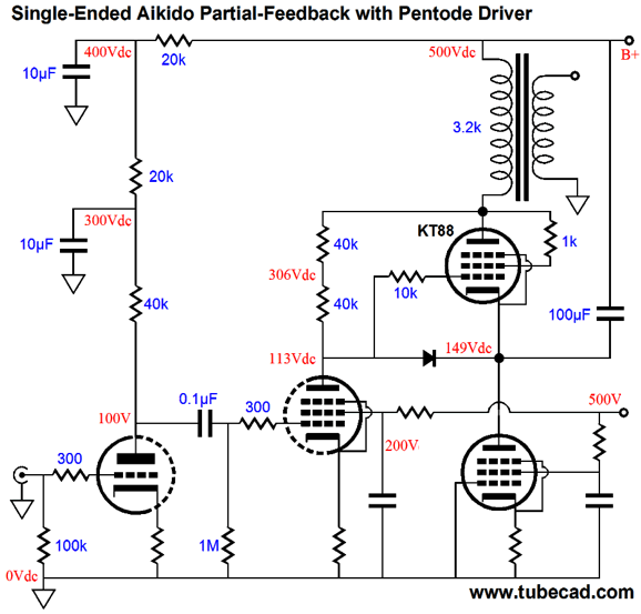
If nothing else, such a design would salvage otherwise unused NOS triode/pentode tubes, such as the 6AU8 and 12CT8, which languish on the shelves. Well, why stop there, as we can use a pentode in place of the two 1k cathode-bias resistors in series.
I would love to see a 6V6 or 6L6 being used. We have, however, two issues: the first is the desired high output impedance and, equally important, low distortion. For what shall it profit an audiophile, if he shall gain the highest output impedance, and lose the low distortion gained by 100% degenerative feedback? Verily, verily, I say. If the Ultra-Empathic output tube is fed a distorted input current, the result will be faithfully reproduced distortion. One way to ensure a clean current output is to wrap a feedback loop around the triode and pentode, creating a proper voltage-to-current converter stage.
What I love about all of these circuits is that they could have been created 40, 50, 60 years ago.
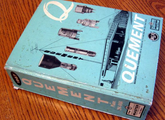
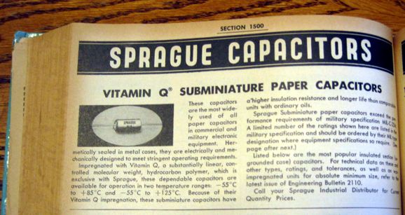
I have a huge, thick catalog (1752 pages no less) , from 1967, produced by an electronics supplier in the heart of Silicon Valley, back when San Jose still billed itself as the prune capital of the world, Quement Electronics. I always wanted to have a contest, wherein you could build any phono stage (or line amplifier or power amplifier) you want, as long as all the parts you used were available in the catalog. It is not as hard as it may sound, as the catalog holds metal-film resistors, which cost $$ each back then, and Vitamin-Q capacitors and even Teflon caps, if I remember correctly—and, of course, many great tubes, such as 211 and RCA 2A3 and 5692 types.
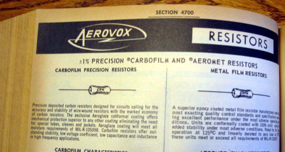
Look, 1% carbon-film and metal film resistors
So many pages of transformers that is make me ache with nostalgia.
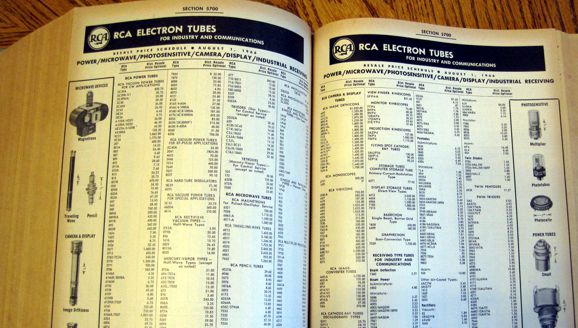
And, of course, vacuum tubes, plenty of them.
|
|
I know that some readers wish to avoid Patreon, so here is a PayPal button instead. Thanks. John Broskie
Kit User Guide PDFs
Only $12.95 TCJ My-Stock DB
Version 2 Improvements *User definable Download or CD ROM www.glass-ware.com |
||
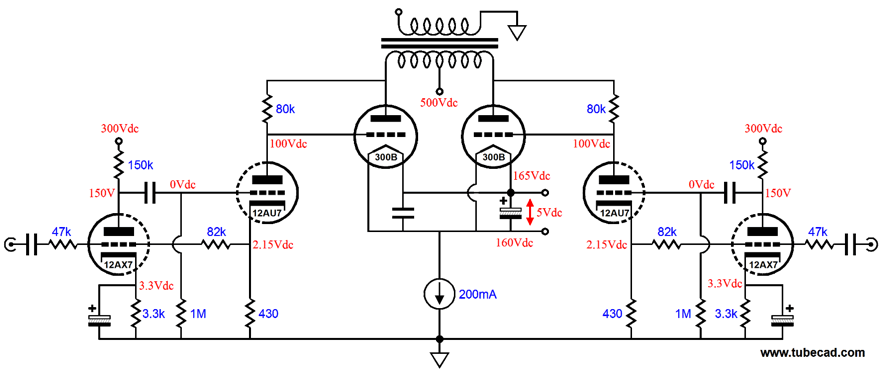
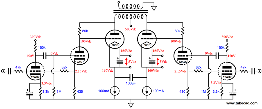
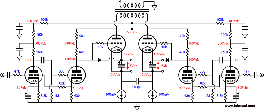
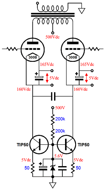
Push-Pull Ultra-Empathic Amplifiers Shown above is a stripped-down schematic, a highly idealized schematic. Missing are the essential grid-stopper resistors, for example. Nonetheless, you can get the feel of the thing. The 12AU7 triodes put out a varying current flow which the 300B output tubes convert into a varying voltage at their plates. No ultra-path capacitor is needed, as the constant-current source isolates the 300B cathodes from the ground, and the joined cathodes and class-A push-pull operation of the output tubes ensure that no shunt capacitor is needed. Interestingly enough, such a schematic would work beautifully in SPICE simulations, but fail miserably in reality. Why? In SPICE, all resistors are 0.00000001% in tolerance, just as all 12AU7 and 300B triodes are perfectly matched. Hell, all the 12AU7s have to be, as they all share the exact same SPICE model. Reality differs. Thus, expecting to get all these DC voltages to align up is as likely as my winning the lotto jackpot. The workaround is to use two constant-current sources, one for each 300B. Yes, each 300B will have to get its own independent 5Vdc filament power supply and its own constant-current source and we will have to add the big 100µF film capacitor to bridge the two cathodes (at least in AC terms). Now, let's flesh out the design. The altogether essential grid-stopper resistors are in place and the 80k feedback resistors have been replaced with two 40k resistors in series. What is still missing is the high-voltage constant-current sources. Here is one possible setup. The TIP50 transistors are 400V devices, so we could cascode a second set atop this set, as the the two 200k resistors provide a ready reference voltage for the top transistor bases. Wow, coming from someone who didn't have enough time, this post has gotten awfully long. Time to empty the dogs.
//JRB
* E = MC² and All That
|
||||


| www.tubecad.com Copyright © 1999-2011 GlassWare All Rights Reserved |