| John Broskie's Guide to Tube Circuit Analysis & Design |
| 18 August 2014 More Hybrid-Amplifier Design
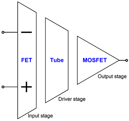
FET-Triode-MOSFET Hybrid Amplifier Last time, we saw a topology that used all three device types in the expected order, but in unexpected configurations.
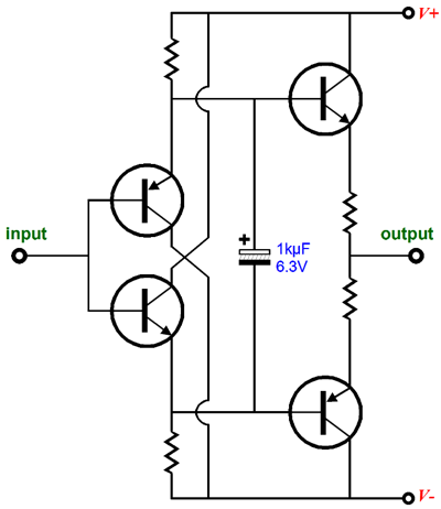
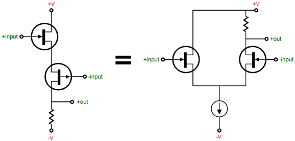
Based on e-mails that I have received, it seems that the Bastode topology is confusing many readers. One reader insisted that the Bastode cannot offer voltage gain, as it is fundamentally a push-pull, unity-gain follower, not an amplifier. I can see how this view could arise; and it certainly would be true, if the external load attached where the two sources (or two emitters) connect. But in the above circuit, no load attaches at that junction, so the circuit cannot function as a follower. The key point there is that where the input signal attaches and where the output is taken makes all the difference in the world. Here is a mind-stretching example, which will use the familiar diamond-buffer topology.
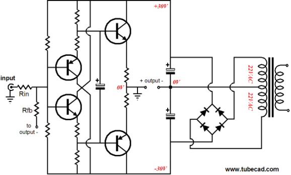
The input goes in at the left and comes out at the right. And that’s all we shall know for truth before we grow old and die.* But what happens if we ground the output and attach the load to the power supply's center voltage? Well, we get an amplifier, an inverting amplifier.
The power supply is floating, i. e. it is not grounded, in spite of the power transformer offering a center tap on its secondary. As the input signal swings positively, the output swings negatively by the amount set by the two feedback resistors, Rin & Rfb. (We could even rearrange things so that the input is grounded and the connection between the two emitter resistors—what was once the output—receives the input signal, which would create a non-inverting amplifier. But that is probably a stretch to far for most.) Returning to the Bastode, the circuit is fundamentally a differential amplifier that does not require a constant-current source (CCS).
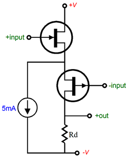
(And no one argues that the differential amplifier on the right is fundamentally a push-pull, unity-gain follower, not an amplifier.) Think about it: the constant-current source only job is to provide a current path to ground or to the negative power-supply rail. Ideally, the CCS impedance is infinite; so, in AC terms, it is effectively not there. As far as the two FETs are concerned, their sources are connected and the CCS presents no resistance to AC signals, which is all that matters in AC terms. In much the same fashion, in the Bastode topology, the two FETs connect at their sources, so no extra current path to the negative power-supply rail is needed, as the P-channel FET on the bottom provides that path; thus, no constant-current source is needed. In other words, the constant-current source was never essential to a differential amplifier; it was just convenient. (In many circuits, it can be replaced by a large inductor. And if inductors were smaller and cheaper, they would replace the active constant-current source.) We could, however, add a constant-current source to Bastode. Why? It would allow us to get both less noise and more gain. Here is an example:
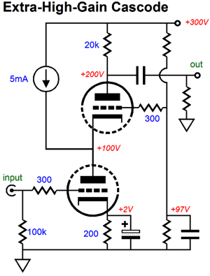
Because the constant-current source offers an infinitely high impedance, it cannot leak away any signal gain. So, what does it do? It allows the top FET to draw more current than the bottom FET, which means that the top FET will add less noise and that the drain resistor, Rd, can be much larger in value, which will produce more gain, as all the signal-induced current variation will flow through the resistor, as the constant-current source must draw a fixed current by definition. A similar trick is sometimes applied to the cascode topology.
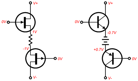
The top and bottom triodes do not share the same current flow, as the bottom triode experiences 10mA of flow, whereas the top triode sees only 5mA stream of current. If the constant-current source were not there, both would see the current flow, as there would be only one path for the current to take. In addition, if the constant-current source were removed and the same idle current used, then the plate resistor would have to be halved in value, which would also halve the potential gain realized. Or, if we remove the constant-current source and alter the cathode resistor value, so only 5mA flows at idle through both triodes, so we could keep the 20k plate resistor value, then the bottom triode's noise contribution would go up and its transconductance would fall off, partially reducing the gain as a result. (Another variation on this theme is to use resistor in place of the constant-current source. This substitution would seem undo the increased-gain feature, as the resistor does present resistance. Well, while it is true that the added resistor does offer resistance, it offers a relatively large amount of resistance compared to the output impedance of the top triode's cathode; thus, a 40k would would draw 5mA in place of the 5mA constant-current source in the above circuit and would result in only slightly less gain than the constant-current source would.) So why isn't the Bastode topology more popular? One big reason: the inputs are not at the same voltage potential. In the FET-based example above, the non-inverting input must be more negative, while the inverting input must be more positive, relative to each other. What a pain. There are a few workarounds; for example, we can place a resistor in between the two sources, but this will lose transconductance; or, we can place a zener in between the two sources, but this will add noise. In either case, it is unlikely that we could ever get both inputs at exactly the same voltage that we can in the conventional differential amplifier that uses a constant-current source and matched FETs. Besides, in the case of two transistors in a Bastode configuration, the resistor or zener trick would never work—although an upside-down battery would, but that is far too much mind stretching for most ;).
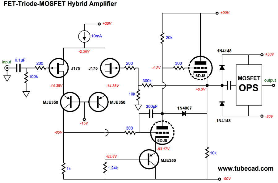
Since the Bastode topology seems to be the stumbling block for so many, I decided to create a FET-triode-MOSFET hybrid amplifier that used a conventional differential amplifier, complete with a constant-current source.
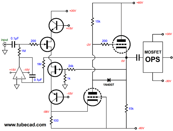
Conventional-Differential-Amplifier Hybrid
The lone MJE350, at the bottom, drives the bottom 6DJ8's cathode. The rather large-valued 1k and 1.2k resistors allow the FET input stage to develop more differential gain to drive the triode. The top 6DJ8 triode functions as a cathode follower. The two 1N4148 diodes are there to protect both the output stage from excessive input signals and the input stage's FETs from too much voltage from the cathode follower. The 300pF capacitor is needed slow-down the driver stage to prevent peaking up in the MHz range. The global negative feedback loop only extends to the cathode follower's output. Why? I would prefer to keep the feedback loop as short as possible. But I must admit that the overall distortion would be lower with the loop terminating at the amplifier's output. If this alternative setup is adapted, then the feedback resistor values could be scaled down by a factor of ten and a small capacitor should be placed across the larger resistor. In other words, a global feedback loop may yield a bit less distortion but at the cost of greatly increased complexity and/or instability.
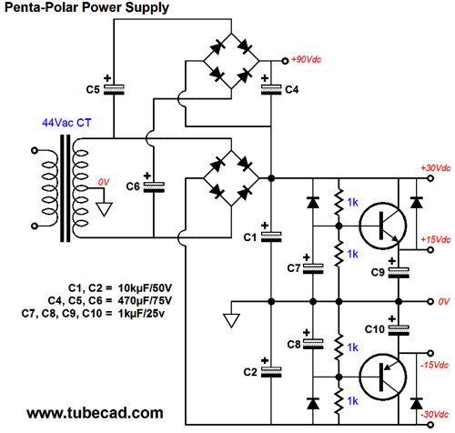
Penta-Polar Power Supply
He asked if a single secondary could be used to create the five needed rail voltages: ±15V for the OpAmp, +150V for the Aikido driver stage, and ±30V for the MOSFET-based output stage. Well, the PS-6 would come in handy, as it can create three of those rail voltages, the ±30V and the +150V from a single 44Vac CT secondary. (I would use a PS-15, as it offers regulated bipolar low-voltage outputs for the OpAmp.) On the other hand, if you can live with only +90V, then the following power-supply circuit is the answer.
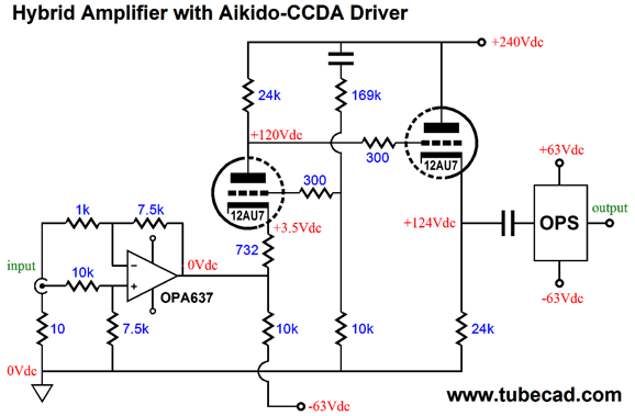
The voltage-tripler circuit converts the 30V rail voltage into a single 90V rail for the tubes, while the two capacitance-multiplier circuits produce about ±15V for the OpAmp. If the nominal rail voltages had been ±70V, the high-voltage output would have been +210Vdc; and the capacitance-multiplier circuits would deliver too much voltage, so the voltage-divider resistors would have to be adjusted or two resistors that terminate into ground replaced by 15V zener diodes. By the way, we can use a different tube-based driver stage. Many are the possibilities. The only topology that I certainly wouldn't use is the SRPP. Why not? Two reasons: a poor PSRR and poor manners, as the gratuitous use of an SRPP circuit marks an amplifier designer as a lazy slob, a thermionic slacker of the first order ;) The following circuit shows a CCDA+ gain stage being used. Why the plus sign? Unlike the typical CCDA, this variation is driven from the input triode's cathode and it uses an Aikido-like power-supply-noise-rejection scheme, wherein a small portion, 1/mu, of the power-supply noise is purposely injected at the grid, which will be amplified and inverted at the plate, thereby nulling the power-supply noise at the output. The 12AU7 provides a gain of about 14, which against the 7.5 from the OPA637 is enough to deliver 200W into 8-ohm loads. Note how only the OpAmp uses a negative feedback loop. (If you are crazy adventurous, you can experiment with extending the loop to encompass the cathode follower's output; and, if even more crazy, the MOSFET's output. Be waned that the OPA637 is a fiendishly squirrelly OpAmp, with limited phase margin. In other words, I would start with an old, slow OpAmp, such as the LM741, then if passes the test, I would work my up with fancier, faster OpAmps, possibly ending with the OPA627.)
Some will immediately note that the 10k resistor that attaches to the the -63V power-supply rail, should be equal to 63/0.005, or 12.6k, if we want the OpAmp to work into 0V at idle; thus, the OPA637 will have to pull up 1.3mA of steady current to achieve 0V at its output. Well, that was my plan, as I want to force the OPA637's output stage to work with a displaced transition out of class-A and into class-B operation. See Blog Number 88. If this resistor is made small enough in value, we can force the OpAmp to run its output stage in single-ended, which is by necessity, class-A throughout.
Next Time
*
A Drinking Song
For those of you who still have old computers running Windows XP (32-bit) or any other Windows 32-bit OS, I have setup the download availability of my old old standards: Tube CAD, SE Amp CAD, and Audio Gadgets. The downloads are at the GlassWare-Yahoo store and the price is only $9.95 for each program. http://glass-ware.stores.yahoo.net/adsoffromgla.html So many have asked that I had to do it. WARNING: THESE THREE PROGRAMS WILL NOT RUN UNDER VISTA 64-Bit or WINDOWS 7 & 8 or any other 64-bit OS. I do plan on remaking all of these programs into 64-bit versions, but it will be a huge ordeal, as programming requires vast chunks of noise-free time, something very rare with children running about. Ideally, I would love to come out with versions that run on iPads and Android-OS tablets.
//JRB |
I know that some readers wish to avoid Patreon, so here is a PayPal button instead. Thanks. John Broskie
Kit User Guide PDFs
E-mail from GlassWare Customers
High-quality, double-sided, extra thick, 2-oz traces, plated-through holes, dual sets of resistor pads and pads for two coupling capacitors. Stereo and mono, octal and 9-pin printed circuit boards available.  Aikido PCBs for as little as $24 http://glass-ware.stores.yahoo.net/
Support the Tube CAD Journal & get an extremely powerful push-pull tube-amplifier simulator for TCJ Push-Pull Calculator
TCJ PPC Version 2 Improvements Rebuilt simulation engine *User definable
Download or CD ROM For more information, please visit our Web site : To purchase, please visit our Yahoo Store: |
|||


| www.tubecad.com Copyright © 1999-2014 GlassWare All Rights Reserved |