| John Broskie's Guide to Tube Circuit Analysis & Design |
|
Post 239 18 Aug 2012
More Past Items
Broskie CF in Solid-State
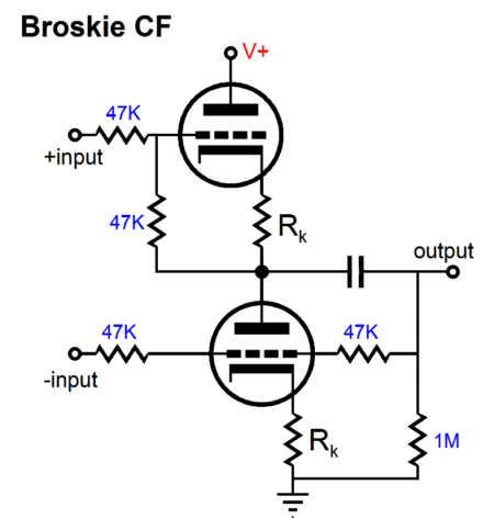
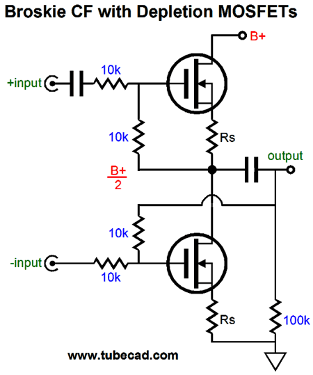
The easiest translation would be to replace triodes with FETs, as both are depletion-mode devices (both can be biased with cathode or source resistor, as the grid and gate can be negative to the cathode or source and yet the devices still conduct).
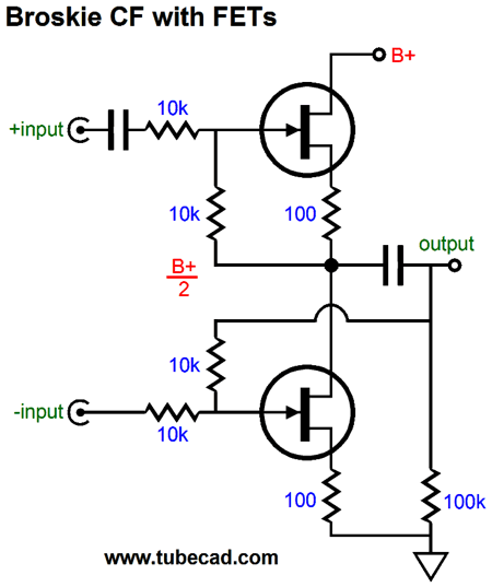
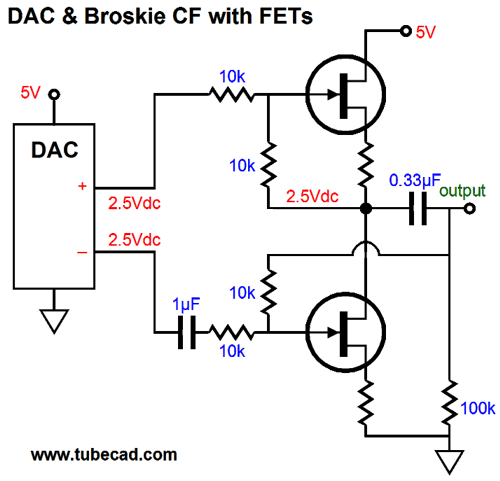
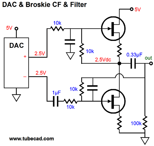
This Broskie source follower uses a monopolar power supply and should use tightly-matched FETs for the best performance. In fact, I worry about the output actually centering, as the typical FET matched pair isn't all that matched. If the input signal comes right off a voltage-out DAC, such as the WM8741 or the AK4393, then the top input coupling capacitor can be omitted.
A low-pass filter can follow the above circuit or the filter's function can be incorporated within the circuit.
From triode to FET to depletion-mode MOSFET is a logical progression.
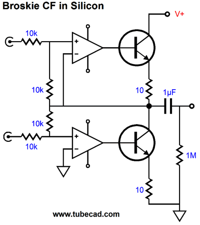
One additional problem we face today is that the catalog actually available FETs shrinks daily. For example, high-voltage (300V) FETs were once made, but no longer. Transistors have also seen a huge dwindling of possible types. On the other hand, transistors are far more generic, so we would have no real pr0blem finding suitable transistors for a Broskie emitter follower. (For example, the ubiquitous P2N2222 NPN type or the 2N3053 are good choices. For low-noise operation, the BC550 or 2N5087 can be used.)
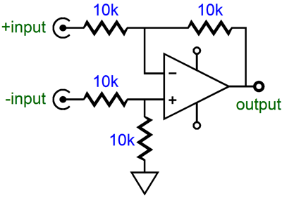
The emitter resistors do not "bias up" the transistors, instead they promote stability and linearity, while preventing current runaway. The two 1k resistors perform the task of getting the the two transistors to center at half the B+ voltage. The assumption behind the values in the above circuit is that a very-low (say +5V) B+ voltage would be used. If a higher B+ voltage is needed, then the values would have to be adjusted. What about OpAmps? Could they be used to make a silicon version of the BCF? The answer is that they could, but such a trip might be unnecessary, as a single OpAmp makes a fine differential amplifier, as shown below.
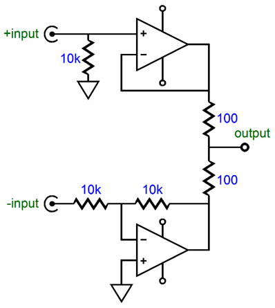
This circuit offers an excellent CMRR and converts a balanced input signal into an unbalanced output signal. Still, it is fun to ask what a two-OpAmp BCF would look like. The following circuit gets close, but does not entirely capture the BCF's functioning.
For example, neither feedback loop attaches directly to the output, as they do in the tube-based BCF. The next variation corrects that discrepancy and makes use of two output transistors and a monopolar power supply for the transistors.
The top input receives the positive input signal, while the bottom input sees the negative input signal. In many ways, the OpAmps function as superchargers for the output transistors, reducing their output impedances and isolating them from the four feedback resistors. One key aspect of the circuit that I must point out is that, as drawn, the circuit isn't truly usable, as no provision was made for establishing the desired idle current through the output transistors or voltage division between transistors. So why show it at all? Understanding, plain and simple. In terms of sonics, I do not believe that the original Broskie CF circuit based on triodes can be beat. I am showing this solid-state version so that the tube version can be better understood, as many audiophiles know OpAmp functioning extremely well. In other words, think of these silicon examples as Rosetta Stones. Another key aspect of the circuit that I must point out is that it should not be mistaken for a Broskie OTL. See Blog number 94.
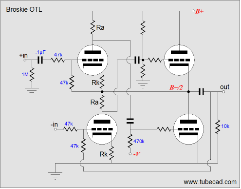
(Ah, remember those skinny lines and gray backgrounds of years past.) The Broskie OTL uses two additional triodes to supercharge the two output tubes. Note how the top input triode drives and controls the bottom output tube, the bottom input triode is in charge of the top output tube. Translating this tube circuit into solid-state will require flipping the OpAmp's inputs, as shown below.
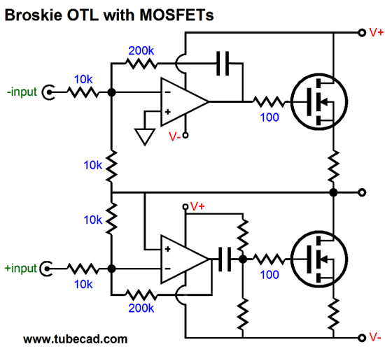
This circuit is closer to being actually functional, as the DC offset is handled, but it, too, needs more embellishment to set the desired idle current through the output transistors. In fact, MOSFETs might be the better choice for output devices, as they require less drive current and their higher turn-on voltage might be an asset, as few OpAmps can truly swing from rail to rail. Moving on to a slightly more actually usable Broskie OTL in silicon is the following design, which uses N-channel enhancement-mode MOSFETs.
The output stage is capacitor-coupled at the bottom MOSFET, so that a fixed idle current through the MOSFETs can be set independent of the OpAmps. The top OpAmp sets the DC offset at the output. Both OpAmps get an additional 200k feedback resistor. These resistors perform two functions: they allow non-unity-gain stable OpAmps to be used and they complete a feedback path to the OpAmp's outputs. For the bottom OpAmp, this function is critical, as this OpAmp would otherwise have no DC feedback path, which is needed to keep its output voltage centered at 0Vdc. Okay, what would a similar output stage arrangement look like in the BCF topology?
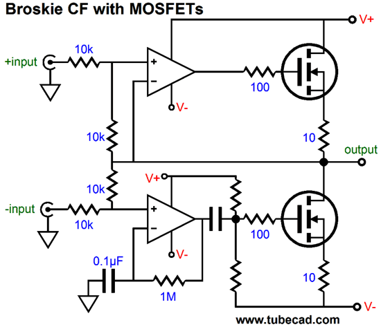
Similar, but certainly not the same as the previous schematic. Once again, the top OpAmp controls the DC offset at the output; the two-resistor voltage divider following the internal coupling capacitor sets the idle current through the MOSFETs. The 1Meg resistor provides the bottom OpAmp with a DC feedback path and the 0.1µF capacitor AC "grounds" its inverting input. But as the bottom MOSFET inverts the signal from the bottom OpAmp, this input effectively become the non-inverting input of the bottom OpAmp and its MOSFET in combination. Please note that I am not recommending any of the OpAmp-based versions of the Broskie CF, as the simple OpAmp differential amplifier is a better choice. On the other hand, the FET-based and transistor-based BCF versions are interesting and could work well in many applications.
SPICE and Easier Solutions
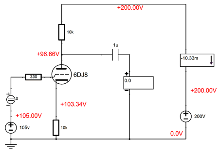
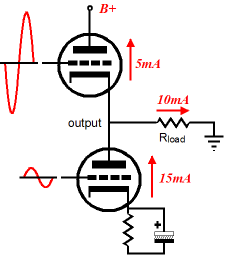
As he saw it, too many triodes and just too complex. His alternative circuit was extremely interesting, but not for the usual audio reasons. No, what interested me the most was the fundamental unreality of the design. This was not his fault and I am not pointing out this feature of his circuit to make fun of him or punish him. His circuit was designed in SPICE and, in the world of SPICE, his circuit works extremely well. Unfortunately, the results in SPICE and those in reality need not overlap—particularly when dealing with tube circuits. Why? The easy answer is that the SPICE tube model is fundamentally wrong; it sees the the triode and pentode as being variable current sources. They aren't; they are variable resistances. Remember, a current source in SPICE is not a current limiter as it is in reality, but a current source in the same way that a battery is a voltage source in reality: it can deliver current all by itself. Do not believe it? Dig out a tube SPICE circuit and set the B+ voltage to zero volts, then run a simulation. Here is an example of SPICE not knowing how to handle a triode:
Looks like a typical split-load phase splitter right? Well, sort of. Note the cathode and plate voltages. How is it possible for the plate to be -6.68V relative to the cathode and yet still conduct over 10mA? How is it possible for electrons to flow from positive to negative? (Or if you are conventionally minded, How is possible for current to flow from a negative to a positive?) The problem is found in the SPICE 6DJ8 model, which states: p k value={34.56e-6*(pwr(v(2),1.5)+pwrs(v(2),1.5))/2 This is a version of the famous Child's three-halves-power formula for a triode's current flow. A better formula would begin with Resistance = ... The lesson here is not that SPICE is worthless; it's not; in fact, it is marvelous. The lesson is garbage in often leads to garbage out, but not always. Remember false propositions can lead to true conclusions.* So, please do use SPICE, as I do daily, but always keep an eye on the assumptions and the results. Okay, back to the easier circuit the reader sent me. I altered the part values only enough to make the circuit work in both reality and SPICE, keeping as much of the original as I could.
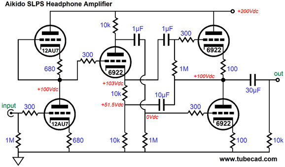
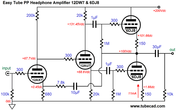
Although this tube amplifier could be used as beefy line-stage amplifier, the amplifier was designed as a tube headphone amplifier, with an intended load of 300-ohms, such as presented by the HD-650 from Sennheiser. The 12AX7 triode provides a lot of gain and 12AU7 triode draws a healthy amount of current. The 6DJ8 output tubes also provide some voltage gain. What is is my opinion of the circuit? I like that the output tube's cathode resistors are not bypassed with large-valued electrolytic capacitors, in spite of the increased output impedance. And I like seeing the 12DW7 being used. What troubles me is the intrinsically unbalanced drive signal that the output stage sees coming from the phase splitter. Unbalanced? Never forget that the bottom triode's cathode is fixed at ground, whereas the top output triode's cathode must move with the output signal. In other words, the bottom triode's grid must see a much smaller drive signal than the top triode; or in other words still, the top triode's grid must see a much larger drive signal than the bottom triode.
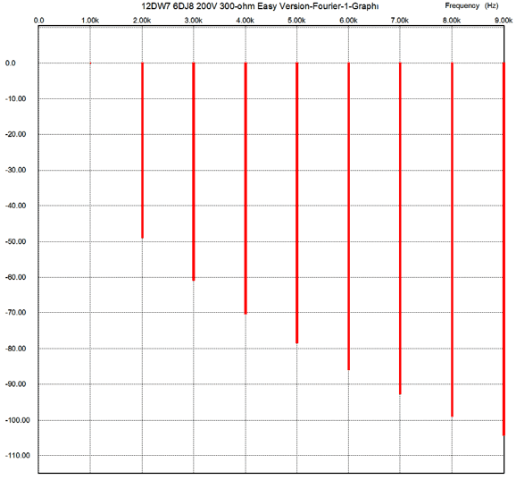
The only time that balanced drive would obtain would be when the load impedance is zero ohms. (Mind you, 16 ohms would be close to zero for the 6DJ8 tubes, but 300 ohms wouldn't be.) See Blog Number 231 for more information. Of course, the assumption here is that the negative feedback will save the day, which is the prevailing wisdom (or faith or religion) of 99% of linear-electronics practice today. Does it save the day? In SPICE, the results are not bad. At 1kHz & 3Vpk into a 300-ohm load, the distortion is below 1% and the Fourier plots display a typically single-ended flavor, the result of the grossly unbalanced drive of the output stage.
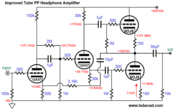
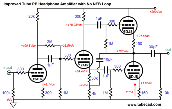
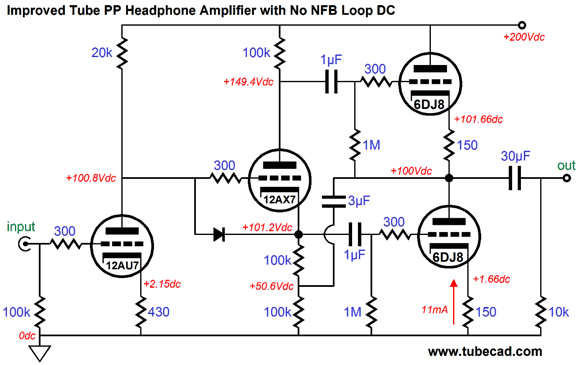
In fact, many readers (and quite a few high-end audio companies) would be happy to stop right here with this proven design and break for lunch. I wasn't. The following remake looks a bit more complicated, but not by much. The tube count remains the same, although I changed the 12DW7 to a 12AX7. Functionally, the two headphone amplifiers work identically: a non-inverting tube headphone amplifier that uses a global feedback loop to tame its output stage, which functions as two grounded-cathode amplifiers. The difference lies in the details.
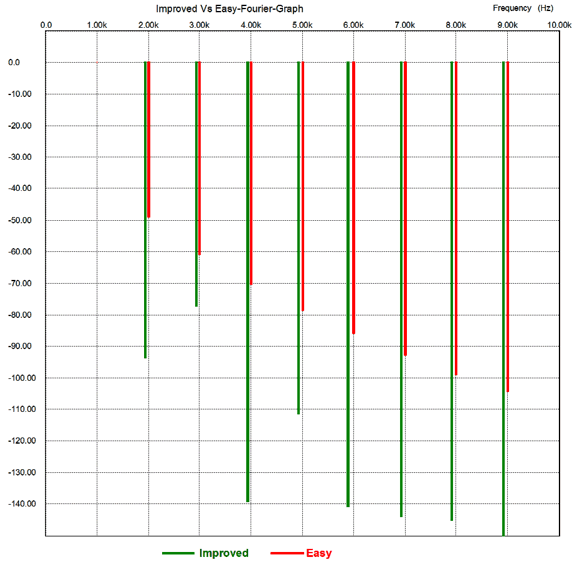
I had three goals: the input stage had to split the B+ noise at its plate, the phase splitter had to deliver a truly balanced drive signal to the output tubes (regardless of the load impedance), and the gain had to remain the same as the original design. The first goal would improve the PSRR figure of the amplifier; the second, the distortion figure; and the last, would make comparisons between the two circuits fair. The last goal is an important one, but often ignored. For example, say my version delivered much better performance, but required four times the input signal. Would this be fair? No, as my circuit would be cheating by providing more negative feedback than the original. So, how does my improved version perform in SPICE? The following graph shows the results of the shootout.
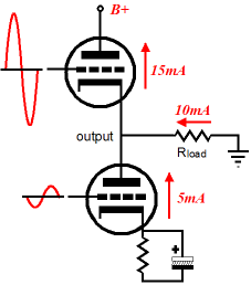
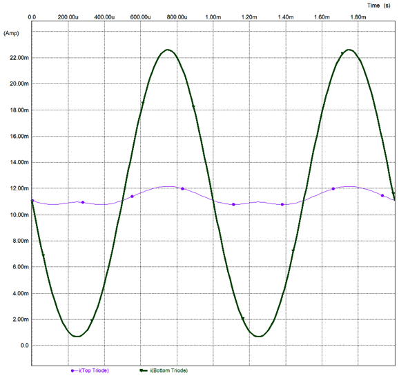
As we can see from the above graph, the distortion is much lower in the improved version. Note how the improved circuit displays a more classic push-pull harmonic structure, which is exactly what we would expect from an improved drive balance between top and bottom output tubes. The improved version also boasts a -4dB improvement in PSRR, but its Zo is, at 30 ohms, 4 ohms higher than the easy version (my version has less open-loop gain). In terms of equal current swings between the output tubes, the improved version is the clear winner, as its balance is near perfect. The easy version, on the other hand, is less so, as the following graph shows. Note how the bottom triode is doing most of the work, which makes sense, as it receives a much larger drive signal. The top triode functions more like an imperfect constant-current source. Very poor balance.
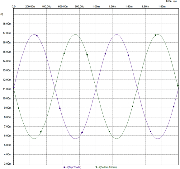
Indeed, note how the bottom triode is being grossly overdriven and how close it is to cutting off. Once the bottom triode cuts off, the amplifier leaves class-A operation. The improved version, in sharp contrast, has a wider class-A window, as shown below.
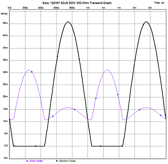
Note how both output triodes have over 5mA of current swing to go before cutting off. In other words, this amplifier can deliver 6Vpk into 300 ohms and still remain in class-A, whereas the easy version will reach its class-A limit at a little over 3Vpk. Both designs can be driven into class-B operation, wherein one output device cuts off completely, while the other does all the work. Do not forget that leaving class-A operation entails penalties, such as poorer PSRR and increased distortion and higher Zo. By the way, the easy version exhibits an odd anomaly, a strange departure from normal push-pull operation: the top output triode never cuts off.
The above graph shows the output tube's current flow under extreme output voltage swing into 300 ohms. Note how the bottom triode cuts off completely, but the top triode lingers on, needlessly dragging down the output. Do not become confused here. This amplifier is still a push-pull, class-AB amplifier—just a poor amplifier. Having the one output device remain on has bought us nothing useful, other than advertising copy. (Last year in AudioXpress, an article claimed that class-A meant that one output device never cutoff in a push-pull amplifier. This is nonsense. A class-A push-pull amplifier is one wherein both output devices never cutoff. The only reason class-A matters to our ears is that both output devices make a meaningful contribution to the sonic result, having one device hang on pointlessly like a bad aftertaste is worse than useless.) Both designs use negative feedback to improve performance. The difference is that my improved design can forgo the negative feedback loop; his easy version cannot. The improved version still produces a clean output signal without a global negative feedback loop, as the two output tubes still see a balanced drive signal because of the 10µF capacitor that connects the output to the phase splitter, thereby creating a balanced drive signal for both output tubes.
In this feedback-free design variation, I decided to use a 12DW7, but with the triodes reversed: the 12AU7 section working as the input tube and the 12AX7 triode operating in the split-load phase splitter. If the phase splitter's plate and cathode resistors are changed in value, the phase splitter's input coupling capacitor can be removed.
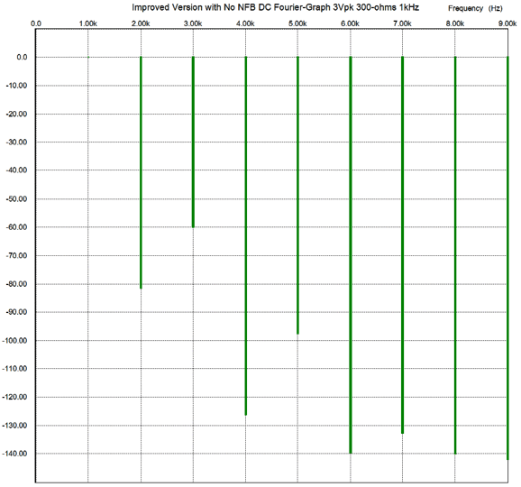
(As I look at it now, I see that another 6DJ8 or 6922 should be used in place of the 12DW7. Why? The12AX7 triode requires a much greater cathode-to-plate voltage to be happy, whereas the 6DJ8's much lower plate resistance allows it to work much better with only 50 volts across it.) So, how does this variation perform in SPICE? Not too shabby, as the distortion is about 0.01% at the same 3Vpk @ 1kHz into 300 ohms. Certainly better than the easy version with a global feedback loop.
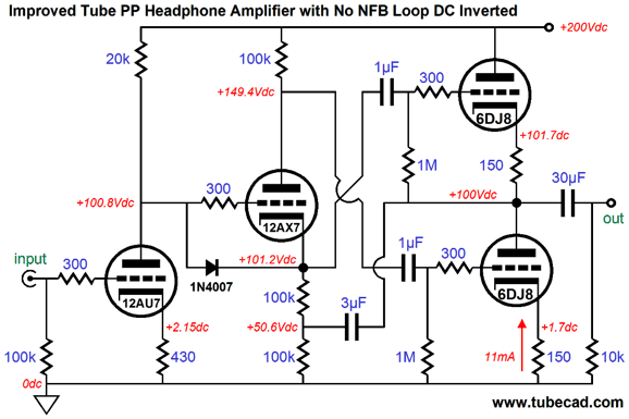
This result is amazing, when you consider that both output triodes function as grounded-cathode amplifiers, not cathode followers. (Imagine a pulse being applied to the output. The pulse would be invisible to the bottom output triode's grid, so it could only counter it with is plate resistance. The pulse would also not be seen by the top triode's grid, as the 3µF capacitor would relay the pulse to the phase splitter's top output, so it, too, could only offer its plate resistance to oppose the pulse.) In other words, this amplifier is closer to being a current-output amplifier than a voltage-output amplifier. This aspect is revealed in its 2300-ohm output impedance. Its PSRR is 6dB worse, coming in at -24dB. Is this the end of the world? No, nothing like it. If a regulated or well-filtered power supply is used, then the slightly poorer PSRR will not be decisive. If the headphones sound better with this amplifier, which they just might due to the high Zo, then its high Zo is not a negative but a plus. Having just written that, I know that many readers will be egregiously irked by the high Zo. Well, there is a simple workaround: just drive the bottom output tube with top output of the phase splitter and the top output tube with the phase splitter's bottom output. This arrangement forces the output tubes to function as cathode follower, with the resulting drop in output impedance.
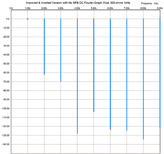
With this topology in place, the Zo drops to 120 ohms. (Bypassing the 150-ohm cathode resistors would halve that impedance.) Since cathode-follower operation also results in lower distortion due to degenerative feedback, what does the distortion look like for the above circuit? Here is the Fourier graph for the above circuit. It looks fairly single-ended, save for the large drop of the 4th harmonic.
How many have already guessed what I am about to suggest? I wonder. Okay, no more suspense-building pauses. What would truly be cool is using a rotary switch to select either feedback-free topology, so we could quickly test the sonic differences between the high and low output impedances. Wait a minute; haven't I forgotten about the phase inversion itself polluting the sonic results? No, I haven't. I would use a balanced input signal, which most DACs offer these days, and which would allow preserving the phase. (Only one of the balanced signals would be used at a time.) I would love to hear this shootout. Understand, that only by forgoing the global negative feedback loop, this switched setup is possible.
The reason that I have not posted all this before was that I have been waiting for the easy circuit's author to get back to me with the results of his actually building and testing both versions. My e-mail to him has bounced for the past few months. He is (or was) a university student and maybe he is still on summer vacation or he might have graduated. (If you read this, James, please contact me again, as I am keen to know what results you obtained from building both versions in the real world.)
Next Time
*Here is an example of bad premises resulting in
Or how about an example of the fallacy of affirming the consequence, i.e. if q then p; p obtains; therefore q is true:
All the premises are false in the two above arguments, but both conclusions are true, although only the first argument logically works. These examples may seem laughably crazy, but the same structure, the same logical topology if you will, occurs all the time in public affairs. In fact, I have known many for whom the only logical reasoning that they follow is the flawed logic of always affirming the consequence. For example:
Hey, no fair, that's gotta be true; everyone one knows that's true! Really, really? Bob may or may not be a racist, but this argument failed to establish this conclusion. It's possible that Bob is the least racist person living. If anything, an argument might be made that those who instinctively and persistently see racism everywhere might themselves be something of a racist—or is that unthinkable or is it more like a thought crime, like imagining the king dead? The only conclusion we could safely draw is that Bob might be a racist, but then he might be a werewolf. In both cases, in the absence of more evidence, I would put the silver bullets away. In his poem "Whispers of Immortality," T. S. Eliot states that Webster always saw "the skull beneath the skin". God bless him, for he was rare indeed. For most, there is only skin and makeup and tattoos and jewelry. If I have learned anything in my over half a century of living it is that most do not see structure or topology or schemes or plexus or schematism or theme or motifs or figures or... It's all invisible, hiding under the surface. But then Nietzsche wouldn't agree, as he stated in the epilogue to his Joyful Wisdom (Gay Science) :
I guess that I just am not that profound... Or, perhaps I am, as he goes on to write: 173 To be Profound and to Appear Profound. He who knows that he is profound strives for clearness; he who would like to appear profound to the multitude strives for obscurity. The multitude thinks everything profound of which it cannot see the bottom; it is so timid and goes so unwillingly into the water. The first quote, typical of Nietzsche, doesn't exactly mean what you might imagine it means. The second quote requires much less head scratching. Indeed, it should be required reading for every academic and should be posted on the masthead of every journal.
While on the topic of fallacious reasoning, forty-two years ago, David Hackett Fisher wrote a fantastically good book, Historians' Fallacies, wherein he listed 11 categories of historical fallacy, each of which subdivided into many sub-fallacies.
Although Fisher's book isn't perfect (he seems to have a few axes to grind), it should be required reading for all historians and students of history. In fact, it should be the first book any history student reads. Audiophile Fallacies If such a book were written about audiophile fallacies, what would the chapter headings be? The Fallacy of equating expense with quality, perhaps? Or, maybe, The fallacy of the audio reviewer being granted an endless loan of the product being reviewed.
//JRB |
|
I know that some readers wish to avoid Patreon, so here is a PayPal button instead. Thanks.
John Broskie
E-mail from GlassWare customers:
And
High-quality, double-sided, extra thick, 2-oz traces, plated-through holes, dual sets of resistor pads and pads for two coupling capacitors. Stereo and mono, octal and 9-pin printed circuit boards available.  Aikido PCBs for as little as $20.40 http://glass-ware.stores.yahoo.net/ Only $12.95 TCJ My-Stock DB
Version 2 Improvements *User definable Download or CD ROM www.glass-ware.com |
||


| www.tubecad.com Copyright © 1999-2012 GlassWare All Rights Reserved |