| John Broskie's Guide to Tube Circuit Analysis & Design |
| Post 238 31 July 2012
The Howland Current Pump Circuit If someone had written, which no one did alas, “Loudspeakers are primarily resistive devices; THEREFORE, they should be driven by current-output amplifiers," he would be no less right and no more wrong, as his argument is equally valid. What?? Yes, indeed, loudspeakers are primarily resistive devices. If they were perfectly resistive devices, with no inductive or reactive contamination, both voltage-output and current-output amplifiers would deliver identical results, as both would deliver identical amounts of voltage and current. For example, if a voltage-output amplifier put out 8Vpk, it would also deliver 1A peak into an 8-ohm resistance; if a current-output amplifier put out 1A peak, it would also deliver 8Vpk into an 8-ohm resistance; no difference. As far as the purely resistive loudspeaker was concerned, both amplifiers would appear the same. Since loudspeakers present complex impedance plots, both the current-output and the voltage-output amplifier yield compromises and less than perfect performance. A voltage-output amplifier produces a fixed output voltage and varying output current; a current-output amplifier, a fixed current and varying output voltage.
In other words, being a “primarily resistive device” does not compel using one amplifier type over another. If any arguments are going to be made, it should be that tubes, in general, would make better current-output amplifiers; and transistors, in general, would make better voltage-output amplifiers. Why? Transistors are primarily voltage-limited devices, whereas tubes are primarily current-limited devices. Thus, it should prove easier to have tubes deliver a relatively low and limited output current, a super-high Zo, and an occasionally exceedingly high output voltage, just as it should prove easier to have transistors deliver a relatively low and limited output voltage, a super-low Zo, and an occasionally exceedingly high output current. Well, this long preamble brings us back to the topic of current-output amplifiers. In particular, the Howland current pump circuit. First, I must mention that the following schematic is the modified Howland circuit, the original being more complex, as I remember it. (Sadly, I cannot find the old schematic of the original circuit.) In addition, the "current-pump" name is unfortunate, as is the "current-source" name that is often also applied to the circuit. As I see it, the best name would be the Howland voltage-to-current converter. The Howland V-to-I circuit maintains a fixed ratio between the input voltage it sees and its output current. In the following example, the ratio is equal to 10mA per input volt. If the 100-ohm series resistor were replaced by a 1-ohm resistor, the ratio would equal 1A/V. In other words, the input voltage will be superimposed across this series resistor; the bigger the resistor value, the smaller the voltage-to-current conversion ratio, as Iout = Vin/Rs.
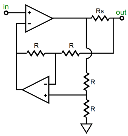
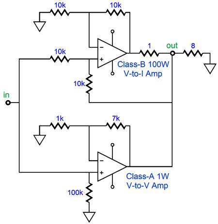
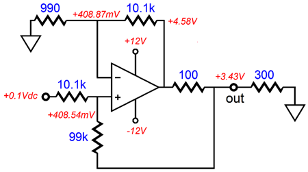
Making things even more confusing, the Howland current pump circuit comes in many forms, such as the following design that uses two amplifiers.
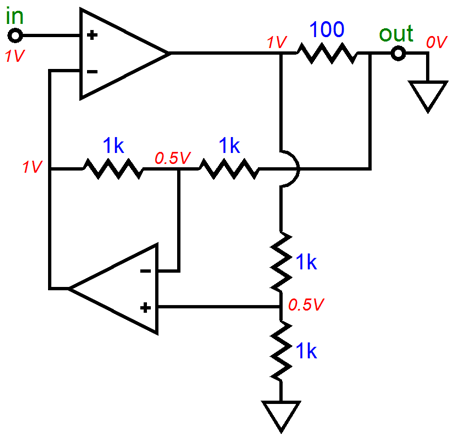
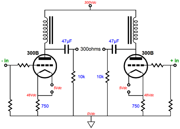
Yes, two amplifiers are more expensive and require more skill in implementing, but they do offer one large advantage: the signal-source impedance is no longer an important factor, as the critical four feedback resistors are shielded from the input signal. (The amplifier within the feedback loop of the other does not need to be a power amplifier, as it only drives the power amplifier's inverting input and its own feedback resistors. In other words, an OpAmp could be used with a power amplifier.) I fear that I am truly jumping too far ahead, but here is the two-amplifier version with example voltages and resistor values. The load is 0-ohms, which is ideal for a current-output amplifier, although it looks wrong, frightfully wrong to our voltage-amplifier-centric eyes. As a homework assignment, imagine a 100-ohm load and the resulting voltages.
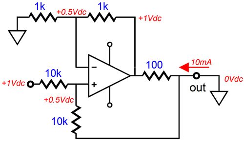
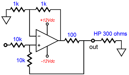
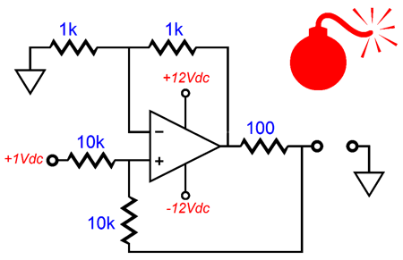
Let's reset our examination of the Howland circuit and begin with just a simple OpAmp-based example that is designed to drive a 300-ohm headphone element.
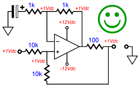
The OpAmp that is used is not important. What is important is the voltage and current relationships within the circuit. The key point to remember is that an OpAmp will use all its considerable open-loop gain to keep both its inverting and its non-inverting inputs in line with each other, i.e. in line in terms of voltage. If the OpAmp's positive input sees 1V, then its negative input must see 1V as well. If the input signal is 0V, then the above circuit's output voltage must also be 0V, as only that voltage will keep the OpAmp's two inputs at the exact same voltage. If we apply a +1V input signal, the following voltages result.
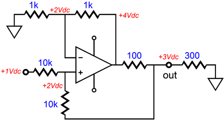
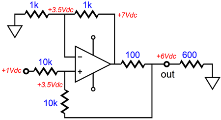
If the input voltage had been -1V, then all the other voltage would be the same, but negative. If the load resistance had been 600 ohms, then the following voltages would result.
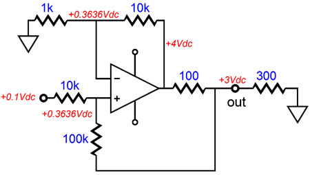
The same voltage-to-current ratio holds, but as 600 ohms is twice as large, it must develop twice the voltage across it, as V = IR. While are at it, note that the 300-ohm requires that the signal source, which provided the 1V signal, must sink 1/10k amount of current, whereas the 600-ohm load setup requires 2.5 times more current sinking, as 2.5V/10k. In other words, working out the input impedance takes some thinking. Do the four feedback resistors have to be the same value? No. In the following example, 1k and 10k and 100k resistors are used, which yield a voltage-to-current ratio of 100mA/V. Note how the 1k/10k pair equals the 10k/100k pair in ratio. (Many of the GainClone power OpAmps, such as the LM3886, require a final voltage gain of at least 10; thus, the following configuration just might work.)
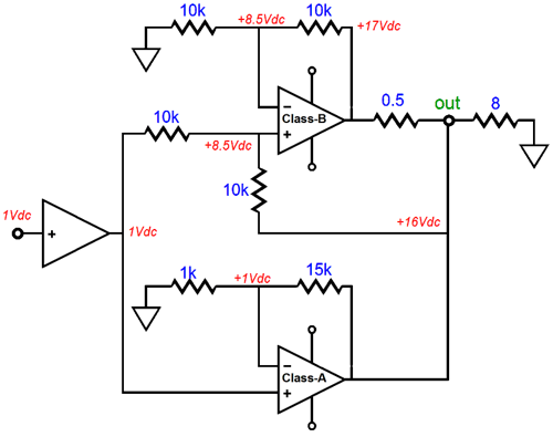
Okay, I assume everyone is getting how the Howland circuit works. The question that should arise is, Other than being a useful current-output-amplifier topology, does the circuit have other uses? Good question. Indeed, yes. Here is my idea: what if we combined a standard voltage amplifier with a Howland V-to-I circuit? The voltage amplifier would be a high-end affair with a class-A output stage, either single-ended or push-pull, but very limited output wattage, say 1W. The Howland current-output amplifier, on the other hand, would be a dirty class-B design, which could deliver 100W. In other words, we would build a mixed-mode amplifier that delivered a voltage output with both a low Zo and low distortion.
Such an amplifier is similar to the old Quad current-dumping amplifier, but certainly not identical. For example, such a hybrid amplifier must always be connected to the external load, like a current-output amplifier and unlike a voltage-output amplifier; but unlike the current-output amplifier, it cannot have its output shorted to ground. In addition, we face the problem of the signal source’s output impedance, which would throw off our exact resistor ratios. The workaround to this last problem might be as simple as adding a unity-gain buffer ahead of the mixed-mode amplifier.
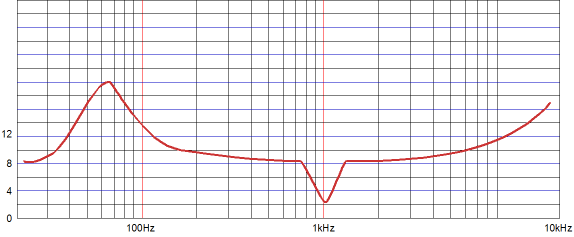
Note that the class-A power amplifier is delivering no current into the load, in the above example, as the current-output amplifier is delivering 2A of current. Ideally, the high-quality voltage amplifier will have the relatively small job of cleaning up the output signal, which should not require much power. (The clean voltage amplifier would still have to swing the same amount of voltage as the dirty V-to-I amplifier.) Well, such would be the correct supposition with purely resistive loudspeakers. With a typical loudspeaker, with its roller coaster impedance plot, the high-quality small amplifier would have a lot more work to do. In fact, the class-A, voltage-out amplifier could easily be overwhelmed. For example, if a 4-ohm speaker were attached, rather than the intended 8-ohm loudspeaker, the voltage-output amplifier would have to deliver just as much current as the current-output amplifier. If a 16-ohm speaker were attached, rather than the intended 8-ohm loudspeaker, the voltage-output amplifier would have to absorb half as much current as the current-output amplifier dumped into the load. In other words, this amplifier would be extremely load-impedance sensitive. Of course, some loudspeakers, such as the old Apogee ribbon speakers, present a wonderfully flat impedance plot. The problem is that few loudspeaker designers care about the impedance plot of their creations, so it is allowed to run wild. This is probably a bigger mistake than most would acknowledge. Using a separate and powered subwoofer could help. If the satellite speaker only covered frequencies above 100Hz, the impedance plot that it presented to the amplifier could be made quite flat. Revisiting the transmission-line enclosure would also be worthwhile, as it, unlike all other enclosure styles, flattens the impedance hump at the woofer's resonate frequency. Another approach would be to make both current-out and voltage-out amplifiers equally powerful, but have the voltage-out amplifier run in rich class-AB and run the current-out amplifier in lean class-B.
The Future
In addition, you can easily buy a headphone jack that shorts the output to ground, when the headphone plug is pulled out of its jack. I can also imagine very expensive current-out tube amplifiers being sold, as there is always a market for insanely expensive stuff.
But, I also predict that eventually a great flat-impedance loudspeaker and a great current-output or mixed-mode amplifier will be created and they will live happily together; perhaps, they will change the audio industry. Before leaving this topic, I must mention that the mix-mode amplifier shown earlier could be made with tubes. It wouldn't be exactly the same, as I would strive to forgo the voltage amplifier's negative feedback loop, relying on a triode's own naturally low plate resistance (rp) to serve in its place. Such an amplifier might use four KT120 pentodes and one or two 300B triodes. The KT120s would be configured in a current-output amplifier and the 300B would run in a class-A single-ended or push-pull voltage amplifier. The resulting amplifier might put 200W that sound as sweet as 20W class-A amplifier. (It is late, otherwise I would draw a schematic.) Another possibility is to build a hybrid mixed-mode amplifier that used a solid-state V-to-I stage that put out big watts and a small tube V-to-V amplifier that put out a clean voltage. The problem is phase shifts due to coupling capacitors and output transformers. Thus, an OTL tube amplifier might be the best choice. Once again, I can see a tube hybrid mixed-mode amplifier more easily being made and sold than a speaker version.
The Howland Circuit and Precision Resistors
An easy workaround is to place a large-valued capacitor in series with the feedback resistor, as shown below.
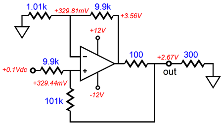
The real difficulty the Howland circuit faces is resistor tolerances. Other than RIAA equalization and active crossover networks, few audio circuits demand tight-tolerance resistors. The Howland circuit does. Here is an example of why 1% just isn't good enough.
The output voltage should have been 3V, not 2.67V. No doubt, some are wondering what the dig deal is, as who really cares what the exact voltage-to-current conversion ratio is? Sure, I can see how a 11% error wouldn't trouble some readers, but what guarantee do you have that both channels will be off in the same direction? For example, the other channel might look like this, with a 14.3% error.
Mind you, these two examples were worst-case for 1% resistors, with 5% or 10% resistors, the results could be insanely off. This is why 0.1% are so often specified in schematics of Howland current pump circuits. By the way, it is fairly easy to find matched resistors in a group of ten 1% resistors. They might be both 9.92k ohms or 10.06k, not 10k.
Next Time
//JRB |
I know that some readers wish to avoid Patreon, so here is a PayPal button instead. Thanks.
John Broskie
E-mail from GlassWare Customers
High-quality, double-sided, extra thick, 2-oz traces, plated-through holes, dual sets of resistor pads and pads for two coupling capacitors. Stereo and mono, octal and 9-pin printed circuit boards available.  Aikido PCBs for as little as $24 http://glass-ware.stores.yahoo.net/
Support the Tube CAD Journal & get an extremely powerful push-pull tube-amplifier simulator for TCJ Push-Pull Calculator
TCJ PPC Version 2 Improvements Rebuilt simulation engine *User definable
Download or CD ROM For more information, please visit our Web site : To purchase, please visit our Yahoo Store: |
|||


| www.tubecad.com Copyright © 1999-2012 GlassWare All Rights Reserved |