| John Broskie's Guide to Tube Circuit Analysis & Design |
Post 231 19 May 2012 Aikido Split-Load Phase Splitter
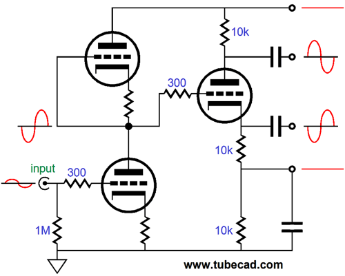
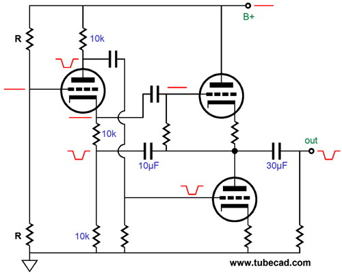
The configuration shown above yields a signal gain roughly equal to one half the mu of the input triodes used. For example, a 12AX7, with a mu of 100, would develop a gain of 50, or +34dB. Note that the split-load phase splitter's output signals, although out of phase with each other, are equal in magnitude. Such a pair of balanced output signals is perfect for the following push-pull output stage, as its signal reference is ground.
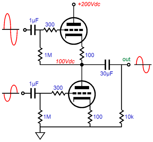
On the other hand, a totem-pole configuration of push-pull output tubes requires asymmetric balanced input signals, as the bottom triode signal reference is ground, but the top triode's reference is the output stage's output.
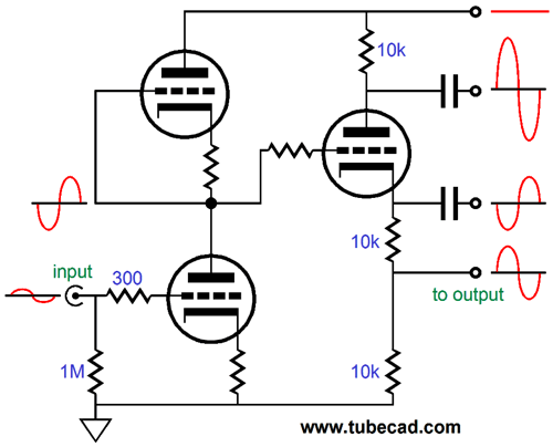
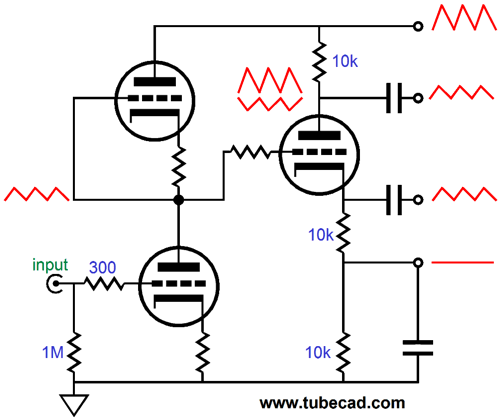
For proper push-pull operation of the output tubes, wherein both tubes undergo equal but anti-phase current swings, both triodes must see equal cathode-to-grid input signals. With one small modification to the Aikido split-load phase splitter, the totem-pole output stage gets just the set of balanced input signals it needs. Note that the bottom 10k resistor is no longer "grounded" via the capacitor; instead, it attaches to the output stage's output (usually via a large valued capacitor).
The asymmetry between output signals bothers many electronic newbies but the asymmetry only exists if we view the signals from the perspective of ground. If we examine the cathode-to-grid voltage relationships within the output stage triodes, we see that both top and bottom triodes see an equal signal.
Okay, now we can move on to power-supply noise elimination from the output stage's output signal. Remember that a push-pull output stage is a differential amplifier, which treats balanced AC voltages as input signals, but largely ignores in-phase input AC signals. A signal transformer is a good example of a device that functions differentially.
If both of the primary leads are tied together and attached to a signal source, no matter how high the signal's amplitude, the secondary sees nothing, as both of the primary leads saw the same signal. On the other hand, if one of the primary leads is grounded and the other lead is attached to a signal source, the secondary sees an AC signal across its leads. In short, if we want a noise free output signal from the push-pull output stage, we must either feed it a noise-free balanced input signal, which is difficult, or a noise-ladened balanced input signal, whose noise is equal in magnitude and in phase.
The input stage splits the power-supply noise and delivers it to the split-load phase splitter. This noise is then passed on in phase by the split-load phase splitter's cathode output. Since the 10k cathode resistor sees this AC noise signal superimposed across its leads, the current flowing the resistor varies accordingly. Since the plate resistor falls in the same current path, it also sees the current variations, creating an anti-phase signal at the plate; in other words, negative noise. Since the negative noise signal is half the magnitude as that found at the B+ connection, the amount of noise at the plate output is equal to 1 - 0.5, or 0.5. Thus, each output from the split-load phase splitter holds the same amount of in-phase power-supply noise.
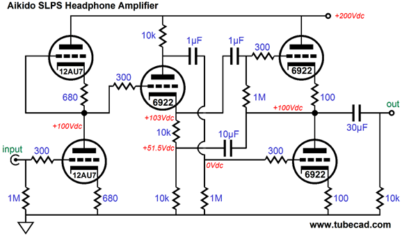
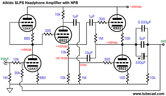
Aikido SLPS Headphone Amplifier Unlike an SRPP or White cathode follower or SRCFPP headphone amplifier, all of which require a known, fixed load impedance, the Aikido SLPS headphone amplifier can work with a wide range of load impedances, as the Aikido split-load phase splitter within it automatically adjusts the balanced output signals for each load impedance attached to the output.
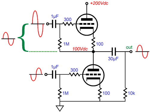
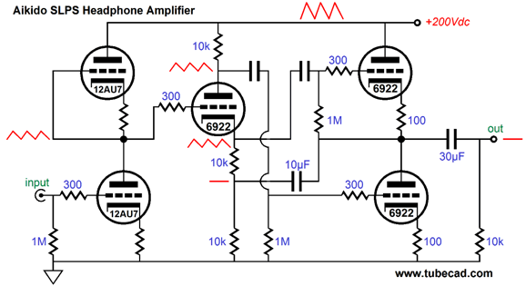
Before anyone asks if other tubes could be used, let me say that I just pulled these tube types out of my hat. Topology is what is important here, not the tube types. Huge 300W radio transmitting triodes could be used as the input tubes and tiny pencil tubes or nuvistors could be used as output tubes. Different tube do not make different topologies. A cube is cube whether its made of gold or carbon or wood or chocolate; as long as it is a regular solid having six congruent square faces, it is a cube. Having said that, I quite like the tubes shown above, but I would also like to use an ECC99 or 5687 or 6H30 or 6BX7 as the output tube. If the lowest noise was my goal, I would use a 6N1P as the input tube. If I planned on using a negative feedback loop to lower the output impedance, then I would use a 12AX7 or 5751 as the input tube. Now let's look into the Aikido-like elimination of power-supply noise from the amplifier's output. The schematic below shows the noise relationships within the amplifier. The input stage halves the power-supply noise; the split-load phase splitter passes this noise to both output tubes; and the two output tubes see the same noise signal, so they both vary their current conduction equally as result; thus, there is no difference in conduction between the output tubes, so there is no difference, no delta to pass on to the external load impedance.
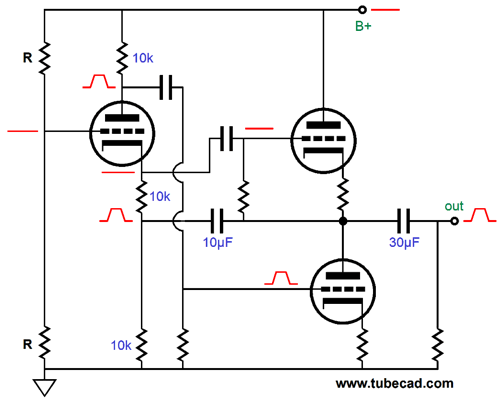
Very cool indeed. I should mention that the wonderful power-supply-noise null only occurs while both output triodes are conducting, i.e. class-A operation. Once one output tube is cutoff, the noise null no longer obtains. When does class-A operation end? When the current output exceeds twice the idle current through the output stage. For example, 20mA, with an idle current of 10mA, which into a 300-ohm load, would equal an output voltage swing of 6Vpeak—plenty loud. But what about output impedance? The best way to examine this aspect of the headphone amplifier is to work backwards by imagining a positive-going pulse applied to the output (by a buffed solid-state power amplifier or a strong battery being quickly attached and then unattached tot he output).
The positive pulse is relayed to the split-load phase splitter via the 10µF capacitor, which then forces the split-load phase splitter's output at its plate produce the positive pulse, causing the bottom output tube's grid to go positive, increasing its conduction, thereby pulling the amplifier's output down. The top output tube will see its cathode being pushed up in voltage, but its grid remains fixed, so the top tube decreases its conduction, causing the amplifier's output to fall. In other words, both output tubes work equally to counter the positive pulse. What happens if a negative-going pulse is applied instead? Everything is much the same, but this time the top output tube increases its conduction, pulling the amplifier's output up; while the bottom tube decreases it conduction, letting the output climb. Once again, both output tubes work equally to counter the pulse.
The key point here is that both output tubes function as cathode followers, in spite of the bottom triode looking like it is configured in a grounded-cathode amplifier topology—it is not. Thus, the output impedance is roughly equal to Zo = [ rp/(mu + 1) + Rk]/2 With 6DJ8/6922 output tubes, the output impedance would be roughly 100 ohms. If the two cathode resistors were bypassed by a large capacitor, the Zo would roughly equal 50 ohms. My preference would be to live with the higher Zo and not use bypass capacitors, as they are very much in the signal path. If a lower output impedance were absolutely required, then a negative feedback loop could be employed.
Next Time
//JRB |
And
High-quality, double-sided, extra thick, 2-oz traces, plated-through holes, dual sets of resistor pads and pads for two coupling capacitors. Stereo and mono, octal and 9-pin printed circuit boards available.
Designed by John Broskie & Made in USA Aikido PCBs for as little as $24 http://glass-ware.stores.yahoo.net/
The Tube CAD Journal's first companion program, TCJ Filter Design lets you design a filter or crossover (passive, OpAmp or tube) without having to check out thick textbooks from the library and without having to breakout the scientific calculator. This program's goal is to provide a quick and easy display not only of the frequency response, but also of the resistor and capacitor values for a passive and active filters and crossovers. TCJ Filter Design is easy to use, but not lightweight, holding over 60 different filter topologies and up to four filter alignments: While the program’s main concern is active filters, solid-state and tube, it also does passive filters. In fact, it can be used to calculate passive crossovers for use with speakers by entering 8 ohms as the terminating resistance. Click on the image below to see the full screen capture.
Tube crossovers are a major part of this program; both buffered and un-buffered tube based filters along with mono-polar and bipolar power supply topologies are covered. Available on a CD-ROM and a downloadable version (4 Megabytes). |
|||


| www.tubecad.com Copyright © 1999-2012 GlassWare All Rights Reserved |