|
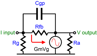
The math is straightforward: F-3 = 1 / (2piRfbC), where, C is the effective grid-to-plate capacitance and Rfb is the feedback resistor. For example, a 300B loaded by 4000 ohms realizes a gain of 3; this amount of gain (gain +1) times the 15 pF of grid-to-plate capacitance equals 60 pF of capacitance, which when combined with a 100k Rfb resistor, returns a upper transition frequency of 26.5 kHz. While this cutoff frequency is still outside the audio band, it is a small fraction of what a 300B could extend to in a comparable cathode follower circuit. Further catches are those catches that all feedback systems are susceptible to: harder clipping and potential instability when faced with reactive loads. But as this feedback loop is indeed short, instability is unlikely to be a problem. Besides the best attribute of this feedback system is that it might eliminate the need for a global feedback loop. If the output stage has low distortion and wide bandwidth and the input and driver stages do not distort greatly, why bother with a global feedback loop, a loop which would have to encompasses many more stages and many more reactive components? Historically, single stage feedback was shunned because it usually increased the drive voltage required, which increased the driver's distortion figure. So while the output's distortion dropped, the front end's increased almost proportionally. In contrast, the global feedback loop reduced all the stages distortions, but at the greater the risk of instability.
Topology Variations As long as a circuit realizes 100% feedback from the output to the input, and as long as a circuit's input has a relatively low input impedance, and as long as resistor, Rfb, is primarily responsible for setting the current-to-voltage conversion ratio, the circuit goal of cleanly converting input currents into output voltages will have been met. Many topologies are possible with vacuum tubes. If nothing else a tube based Op-Amp can be made that will work as a plug-in replacement for the solid-state Op-Amp. But a simpler circuit is preferable. |
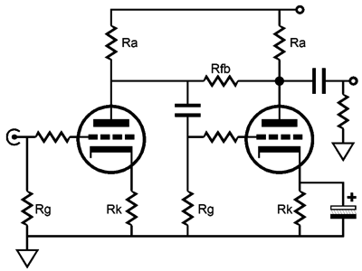
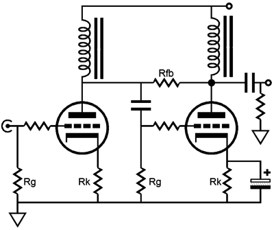
Two similar topologies are shown below.
Both variations offer the advantage of not heating resistor Rfb at idle, as the resistor sees the same voltage at each of its ends. In addition, the lack of a voltage drop across allows a potentiometer to replace the resistor without upsetting the operating and bias points. The disadvantage to the second variation lies in the limitations of the choke used to load the first stage. Inductors need low impedances to bite on and the large valued cathode resistor used in the previous stage guarantees a high output impedance from this stage. The higher the impedance, the greater the inductance value needs to be. The greater the inductance, the higher the DCR of the choke and the higher the inter-winding coupling capacitance between layers, the higher the susceptibility to airborne hum pickup (mutual inductance between other chokes and transformers), and the more readily the choke saturates. The output transformer on the other hand, finds the low impedance it wants to see in feedback reduced output impedance of output tube; even a pentode will offer some bite. |
|
| www.tubecad.com Copyright © 2001 GlassWare All Rights Reserved |