| The Precise Formulas The I-to-V converter's precise formulas must include the dragging effect the grid bias resistor, the plate resistor and the rp of the output tube. The gain is lessened by the grid bias resistor siphoning away a small portion of the input current. Thus, the conversion ratio is precisely given by: Ratio = I(GainRgRfb) / (Rfb + Rg[1+ Gain]) The output impedance for a triode based I-to-V converter must take the shunting effect of plate resistor and resistors Rfb and Rg and is given by: Zo = (Rfb + Rg) || Ra || rp || (rp/mu x [Rg+Rfb]/Rg) And for a pentode based I-to-V converter is given by: Zo = ([Rg + Rfb]/Rg)/Gm || Ra. The input impedance for either tube type is roughly given by: Zin = Rg || (Zo + Rfb) / (gain +1)
I-to-V Output Stages An I-to-V converter's output can be used to power a loudspeaker, if the devices used are robust enough. In fact, some have argued that usual configuration of DAC to I-to-V converter to line stage to power amplifier to speaker should be replaced with DAC to I-to-V converter to speaker. The assumption being that the less intermediate stages the better the sound. The volume could adjusted by presenting the DAC's output a varying resistance, which would shunt more or less current away from the I-to-V converter qua amplifier's input. ("Qua" is a great little word meaning "acting in the function of." For example, "NOS 300B qua family heirloom.") But let us stretch this idea even further: what if we used a tube based I-to-V converter that could swing huge voltages but moderate current swings directly into an electrostatic loudspeaker stators, bypassing the need for a step-up transformer and, possibly, the need for a separate polarizing power supply? The I-to-V converter allows for some amazing tricks to be performed, but let's not jump to far forward. |
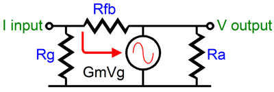
The shunting resistor, Rfb, sets the conversion ratio; the larger the value, the greater the conversion. For example, a 10k resistor converts a 1 mA input current pulse into a 10 volt pulse and a 100k resistor yields a 100 volt pulse. The amazing part is that the input current against the resistor's value equals the output voltage, this circuit is not an amplifier in the usual sense in that it does not have a gain, but rather a relative efficiency. For example, a 300B based I-to-V converter with a 100k Rfb resistor, yields about 80 volts of swing when presented with the 1 mA current pulse. The 300B's gain in a grounded cathode amplifier cannot exceed its mu, about 4, yet the output equals 80 volts. This is a rather good trick, as we seemingly get more gain than would otherwise be possible. The second trick is the low output impedance of the I-to-V converter. No doubt many readers will have noted that the output impedance equals that of the same tube used in a cathode follower circuit. This stands to reason, as what the feedback resistor does is return all the gain to the grid, just as a cathode follower returns all the gain to the cathode. The cathode has an effective transconductance slightly greater than the grid's: in a triode, it equals (mu + 1) / rp, which matches the effective Gm of the I-to-V converter's plate and grid working in unison. Well, since this circuit matches the cathode follower in Zo, why not use a cathode follower instead? The problem with using a cathode follower as an output stage is that it requires a huge input voltage swing. So large in fact that often the cathode follower's low distortion is undermined by the distortion from the input and driver stages. Additionally, the driver stage often requires a greater power supply voltage than the cathode follower output stage to allow such huge voltage swings. This is the price we pay for the cathode follower's extremely high input impedance. The I-to-V converter, on the other hand, can be fed from a current source whose power supply amounts to only 5 volts, as ideally the input of the converter never sees any voltage swings, only current swings. Ok. Where is the catch? The catch comes in the form of a limit to the useable value for the series resistor. If too low, the resistor becomes a heavy in itself. If too high, the high-end falls off. This resistor is shunted by the Miller effect capacitance of the output stage and this capacitance will limit the high frequency response of the I-to-V converter.
|
|
| www.tubecad.com Copyright © 2001 GlassWare All Rights Reserved |