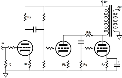
| An alternative topology uses the resistor Rfb to function as a current path for the previous stage. Note how the word "path" was used instead of "load." ideally, the input to an I-to-V converter should be zero ohms. Nothing close to zero ohms is attainable with the triode's limited gain, however.
The next question is How much idle current for the previous stage? You see, in this and the last topology variation, the first stage is a V-to-I converter that must have an idle current at least equal to the peak current swing, if it is to function cleanly, as it is truly a single-ended, Class A circuit that must be able to give up as much current conduction as it draw at peaks. Thus, the idle current for this stage must at least equal the peak expected current signal into the I-to-V converter. For example, if we want to see a 100 volt swing at the output of the I-to-V converter and if the resistor Rfb's value is 100k, then the peak current swing into the I-to-V converter is 1 mA; consequently, this amount of current is also the minimum idle current for the V-to-I converter stage. Greatly increasing this idle current might seem a good idea, as a higher idle current decreases the percentage of the current swing into the gooey bottom of the tube's plate curves. However, such as an increase in current often runs into a snag; for example, 10 mA against a 80k resistor develops a voltage of 820 volts, almost certainly exceeding the power supply voltage of the amplifier, even if the output tube is cathode biased! The solution is to scale back the current to a value compatible with the circuit's operation points. Here is where a high gain output tube or an inductive load is very desirable. In fact, the inductive load allows virtually any idle current greater than the peak current to be used. |
Power Amplifier Design Example Let's go through the steps of designing a "partial feedback" output stage. (By the way, the name "partial feedback" was never explained. It probably refers to the only partial span of the feedback loop that does not wrap across the entire amplifier or to the only partial realization of the feedback because of the non-infinite output impedance of the driver stage.) Remember, when designing power amplifiers, work backwards. Start with the load, then work back to the output stage, then to the driver stage, then to the input stage. Why just three stages? Why not five stages? The answer is more historic than reasoned: three stages has worked well from the Futterman OTLs to most modern transistor amplifiers. If you can get away with two stage, all the better. Adding more stages, however, does ease up the design requirements for each stage, but it also risks greater instability (in feedback based amplifiers) and poorer bandwidth. (For the more inquisitive readers, I recommend that you put away the hi-fi magazines and search out schematics for old tube based oscilloscopes, as these electronic instruments contained some very high gain amplifiers that seldom used feedback to extend bandwidth.) Beginning at the end, the load is, no doubt, an 8 ohm speaker; the output stage, a single-ended transformer-coupled 300B ground cathode amplifier modified into an I-to-V converter; the driver stage, a voltage-to-current converter, i.e. a high output impedance voltage amplifier; the input stage, a simple grounded cathode voltage amplifier. Now in greater detail. A single-ended 300B output stage can be modeled in SE Amp CAD or worked out with a set of plate curves or taken from the Western Electric literature or lifted from a magazine article.
|
|

| www.tubecad.com Copyright © 2001 GlassWare All Rights Reserved |