| John Broskie's Guide to Tube Circuit Analysis & Design |
| 03 May 2014 MORE
Supercharged OTL Speaking of leaps, the great French philosopher and mathematician, Rene Descartes, erased many intervening steps in his mathematical reasoning, which imparted the impression of inspired genius—which, of course, he perfectly embodied, but he wanted to make sure you were aware of the fact.
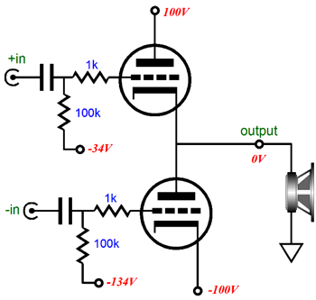
A quick recap: we saw that, besides the output tubes own maximum dissipation and current limitations, two other OTL limitations were positive-grid voltages and fixed power supply voltages—both of which could be overcome by changes in topology. For example, driving the output tube grids with DC-coupled cathode followers allowed the grids to be driven positively, in a low-distortion fashion, freeing up more current flow from the output tubes. Class-G topology allowed the power-supply rail voltages to expand with the need for more cathode-to-plate voltage; and cascode-like topologies would allow either establishing a constant cathode-to-plate voltage or a varying cathode-to-plate voltage situated half-way in between what conventional totem-pole OTL topology and the constant cathode-to-plate configuration, which gave to the rail voltage 50% of what the OTL’s output voltage swing was. Now let’s move forward. The big problem in designing an OTL power amplifier is that vacuum tubes are voltage-strong, but current-weak. If loudspeaker impedance were in the hundreds of ohms, this would be a feature. Alas, speakers are nominally 8-ohm loads, with 4-ohm speakers being fairly common. In contrast, power transistors are voltage-weak and current-strong, which explains in a nutshell why transistor-based power amplifiers replaced tube-based amplifiers in most homes. (Musicians and some audiophiles, being more attuned to sonic texture, refused to give up on tube-based amplifiers.) If output transformers were both small and cheap, tube amplifiers might have fought a longer fight, as the output transformer allows the low-current output tubes to drive low-impedance loads. But since the whole point to an OTL power amplifier is its forbearance of an output transformer, it must deliver high current on its own. So, our task is to find a way to wring even more current from the OTL’s output tubes.
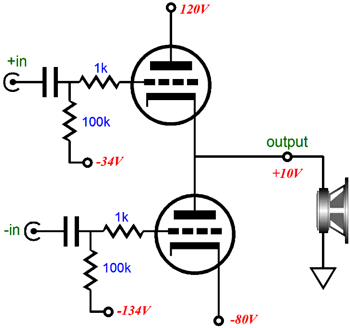
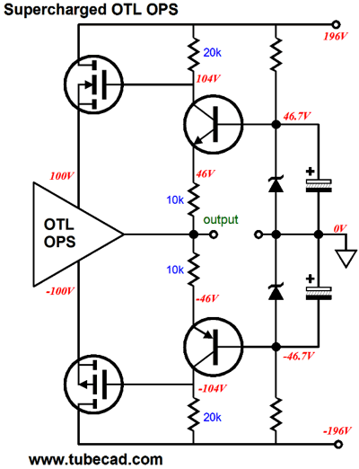
The move to a fixed cathode-to-plate voltage was a move in the right direction, as it allowed for much higher output current swings. Well, my next thought was: What if we applied voltage gain to the output stage rail voltages; not partial or constant cathode-to-plate voltages, but exaggerated cathode-to-plate voltage? In other words, what would happen if power-supply rail voltages increased more than the OTL’s output fluctuated in output voltage? Here is an example: if the speaker sees a positive 10V voltage swing, then the top output tube’s plate voltage would increase by +20V, going from 100V at idle up to 120V; in turn, the bottom output triode's cathode would see 20V less voltage, which would lessen the demands made on its grid signal, as the triode would conducts less with the positive change in cathode voltage.
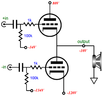
Note that the two output tubes sit in a 200V voltage differential at idle, and that they continue to do so even after the change in rail voltages. If the output swings 10V negatively, then the following voltages obtain.
Once again a 200V voltage differential from top to bottom. But this time the bottom triode gets to draw more current. Let's back up a bit, as I don't want to leave any readers behind. A triode’s plate is, like the grid, a current-control element; as the plate voltage increases, so, too, does current conduction from cathode to plate; as it decreases, its conduction decreases. Of course, the grid is much more effective, being mu times more effective by definition than the plate in controlling current flow through the triode. (The cathode is (mu + 1)/mu more effective than the grid and mu +1 times more effective than the plate.) Because the plate is not nearly as effective as the grid, we are not likely to run into a positive-feedback death spiral, wherein the output goes positive and then evermore positive until the triode melts.
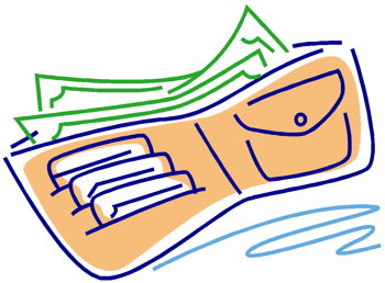
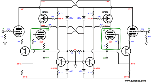
Imagine that you have been living under a tight budget, stretching each dollar as far as you can. Life is fairly miserable. Then, one lucky day, you find a magic wallet. Each time you take out a twenty to spend, forty dollars appears inside it. Life just became much more pleasant. Well, that's how the output triodes feel, if they could feel, as the speaker sees +40Vpk the top triode’s plate voltage increases by 80Vpk, allowing the triode to pass much more current, as this triode effectively sees a 40V increase in cathode-to-plate voltage. This setup would make for a relatively low dissipation at idle and still allow much more power to be delivered to the loudspeaker. Yes, the output tubes would still get banged around a bit, much as a car with a supercharger gets driven harder, as it is much more fun to drive. But the assumption is that quality music is the signal source, not steady sine waves. Good music ebbs and flows, builds to crescendo and relapses into a calm passage; in other words, it exhibits a wide dynamic range. The average amount of power delivered to your speakers is only a few watts, even if the playing is loud. Well, at least it should be. Organ music and synthesizer music can make heavy and steady demands on a power amplifier, much in the same way that sine-wave generator would. (This argues for a good subwoofer with its own solid-state power amplifier.) By the way, a car’s supercharger is a good analogy to this OTL on steroids design. A supercharger effectively increases a car engine’s cubic displacement, compressing its air intake, making a 2-liter engine act as if its displacement were 2.6 liters. Okay, now that we have an objective, how do we achieve it? It being the application of voltage gain to the power-supply rail voltages based on the OTL’s output voltage swing. All good engineers have the same goals for an engineering solution: effective, simple, and inexpensive. Sometimes, we can only get effective; other times, effective and complex, which usually precludes inexpensive. Getting all three is tough. The following schematic shows what I came up with and I will let you decide how close I came to achieving all three goals.
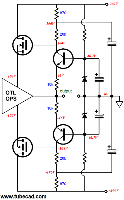
The transistors are configured as grounded-base amplifiers, which are analogous to the grounded-grid amplifier. Their input signal is the OTL’s output. Their gain is set by the ratio between the collector and emitter resistors; in this case, two to one, in other words a gain of 2 or +6dB. The collectors attach to the power MOSFET’s gates, so the MOSFETs function as source followers. The result is that the power-supply rails dynamically expand and contract with the output signal, allowing much more power to be delivered to the loudspeaker while lowering the plate dissipation. (The power MOSFETs, on the other hand, will dissipate heat; in fact, at idle, they will dissipate almost as much the output triode plates do.) Okay, make sure that your seatbelts are fastened, as I am about to make big leap. The above scheme is a good one, but it does suffer from one flaw: no PSRR enhancement, which is my signature trademark. Note how the transistor collectors offer very high impedances, nearly infinite impedances, which imply that no voltage division will occur with the power-supply noise. In other words, the entire power-supply rail ripple will be presented to the output tubes. (Most high-end-audio designers would live with this result. How do I know? I have talked to several and most grow impatient or nervous when I bring the subject PSRR enhancement, seemingly finding the topic too indelicate for polite conversation.) One workaround would be to add an RC filter at each end.
The added 870-ohm resistors and the two large-valued capacitors define RC filters that will shield the MOSFET gates from most of the power-supply noise. This is the brute-force technique; and the bigger in value the resistors and capacitors are the more brutal, more effective, the result will be. An alternative approach would be to null the power-supply noise at the gates by introducing a countervailing noise. Very Aikido. Here is what I have in mind.
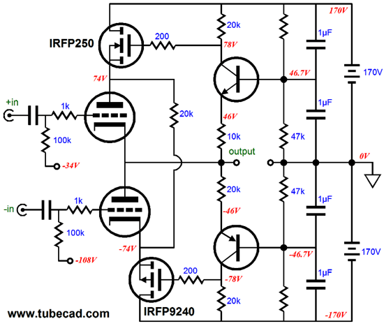
Note how the two 1µF capacitors define a 50% AC voltage divider, so half of the power-supply noise will be presented to the transistor bases, which in turn means that this signal will be impressed upon the 10k resistors, which will result in 100% of the power supply being impressed upon the 20k resistors—but in anti-phase, as the transistors will in this function act as grounded-emitter amplifiers, not grounded-base amplifiers. The 20k resistor that spans between the two MOSFET sources is there to keep both MOSFETs conducting some current, even as its adjoining triode cuts off. The rail voltage were reduced to +/-170Vdc, as those are easy rail voltage to create, being the result of rectifying 120Vac windings.
Next Time
For those of you who still have old computers running Windows XP (32-bit) or any other Windows 32-bit OS, I have setup the download availability of my old old standards: Tube CAD, SE Amp CAD, and Audio Gadgets. The downloads are at the GlassWare-Yahoo store and the price is only $9.95 for each program. http://glass-ware.stores.yahoo.net/adsoffromgla.html So many have asked that I had to do it. WARNING: THESE THREE PROGRAMS WILL NOT RUN UNDER VISTA 64-Bit or WINDOWS 7 & 8 or any other 64-bit OS. I do plan on remaking all of these programs into 64-bit versions, but it will be a huge ordeal, as programming requires vast chunks of noise-free time, something very rare with children running about. Ideally, I would love to come out with versions that run on iPads and Android-OS tablets.
//JRB |
I know that some readers wish to avoid Patreon, so here is a PayPal button instead. Thanks. John Broskie
Kit User Guide PDFs
E-mail from GlassWare Customers
High-quality, double-sided, extra thick, 2-oz traces, plated-through holes, dual sets of resistor pads and pads for two coupling capacitors. Stereo and mono, octal and 9-pin printed circuit boards available.  Aikido PCBs for as little as $24 http://glass-ware.stores.yahoo.net/
Support the Tube CAD Journal & get an extremely powerful push-pull tube-amplifier simulator for TCJ Push-Pull Calculator
TCJ PPC Version 2 Improvements Rebuilt simulation engine *User definable
Download or CD ROM For more information, please visit our Web site : To purchase, please visit our Yahoo Store: |
|||


| www.tubecad.com Copyright © 1999-2014 GlassWare All Rights Reserved |