20 December 2004
About 15 years ago, living as a bachelor with a fat cat (literally a feline, I mean) in a small bungalow, my closest neighbor a 145-lbs black panther (literally a feline, I mean) I wanted to do something special with my Christmas tree. It was the top half of an artificial tree and it stood about three feet tall. I took 22 used, octal, 6.3-volt, 600mA, controlled-warm-up tubes (mostly 6SN7s) and 22 octal tube sockets and an old extension cord and wired all the sockets in series. Then I plugged the series into a wall socket and reveled in the soft glow of 22 tubes (yes, I know only 20 were actually needed). To add a bit more color, I dug out my biggest, most colorful film caps (about 40) and bent one lead over into a hook to hang from the tree—plus any other shiny electronic part I could find.

I still get a warm feeling when I think of it.
I am as often wrong as I am right. I expected to get many e-mails dealing with the Aikido amplifier, particularly its use in an SE amplifier; and I did. But I also expected to get many e-mails dealing with the SS SRPP (the transistor-based SRPP amplifier). None were forthcoming. But a few wrote asking about the MOSFET-based White cathode follower (if only to find out where I had mentioned the topology before). My guess is that transistors are just too creepy for most tube fanciers. (Interestingly, many of these same audiophiles are not bothered by our little silicon friends when they can't see them, when they are imbedded in a DAC or OpAmp for example.)
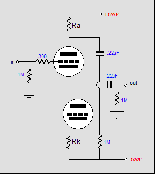 Classic White cathode follower
Before looking at a MOSFET WCF, let's do a quick review of the tube-based follower. Above, a classic White cathode follower is displayed. The top triode receives the input signal and it, in turn, drives the bottom triode. In other words, the WCF performs push-pull operation on the cheap, as it contains its own phase splitter. What is the payoff, considering the added complexity? Optimally, the circuit can deliver close to twice the idle current into its load, and with half the output impedance of a comparable cathode follower. Additionally, the distortion should be reduced because of the push-pull operation of a class-A output stage. Class-A operation is a key feature, as the top triode can control the bottom triode only while it conducts; no conduction, no control.
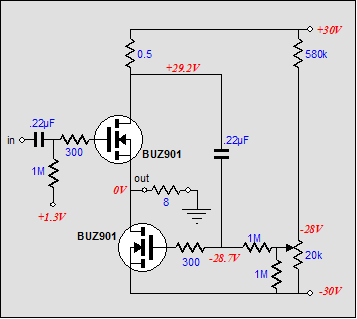
The same principle of operation applies to the MOSFET-based version of the classic circuit, excepting the the biasing arrangement, when enhancement MOSFETs are used.
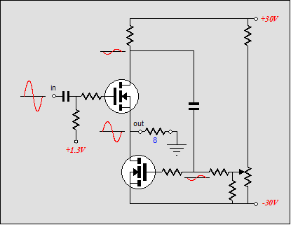
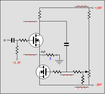
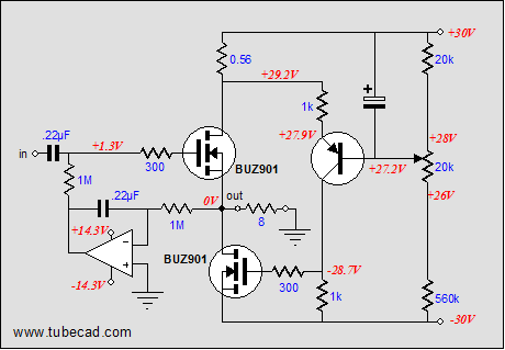
The schematic above shows how easy the translation to silicon is to make. This circuit can be used as an unity-gain buffer, line stage, or power amplifier. As shown, the circuit defines a power amplifier capable of delivering about 36W into an 8-ohm load. The BUZ901 is an excellent lateral MOSFET that beats the pants off anything I have seen from International Rectifier. (If not available, then the Toshiba 2SK1530 is a good substitute.) Although rated 125W, 1.5A at 30 volts equals a lot of continuous heat dissipation for the BUZ901. Below is the BUZ901’s safe-operating-area graph. Note how close we come to the safe DC limit. 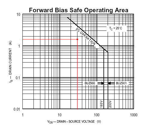
Our nice looking, great-performing-in-SPICE power buffer suffers from one large problem, and it isn’t a high input capacitance. The real world is populated with less-than-ideal power supplies, as power supply regulation is rare and expensive in a power amplifier. Unfortunately, this circuit cannot discern input signal from power supply noise. The problem lies with the sense resistor that develops the bottom MOSFET’s drive signal, as it attaches to the positive rail, not ground. Thus, whatever noise is differentially present from the positive to negative power-supply rails will be seen as a signal to amplify. (A triode-based WCF with the similar bipolar power supply arrangement will suffer from the same failing.)
The solution is found in extracting only the audio signal—not the noise—across the sense resistor. One method would be to use a 1-to-1 coupling transformer, which would offer the potential advantage of doing away with the DC drop across the resistor, if the transformer’s primary held a lower DCR. But the more likely scenario is that the transformer will only introduce more new problems to the mix, as the transformer would need to be air-gapped and capable of withstanding a 1.5A idle current. 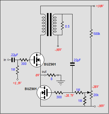
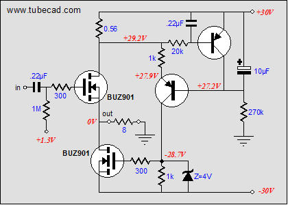
The cheaper and better solution is to add a PNP transistor to the circuit. In the schematic below I have added two resistors, R1 and R2, and a PNP transistor. The transistor’s base is locked; thus, so too is its emitter. As the sense resistor experiences current variations through it, it develops a varying voltage across its leads, which is then relayed to the bottom MOSFET’s gate via the varying current through resistor R2. Note that there was no phase inversion. Had the transistor’s base received the input signal rather than its emitter, the phase would have been inverted.
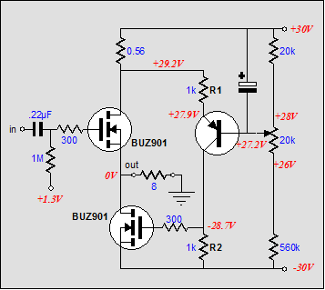
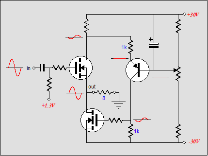
Taylor source follower
Looking at the circuit in terms of power supply noise, we see the following picture: the transistor’s base is “grounded” at the positive rail and its emitter sees virtually all of the positive rail’s noise; thus, there’s no difference to amplify or relay to the bottom resistor. Unlike a triode, the transistor doesn’t hold any “rp,” so its collector is free to ride with the negative power supply rail’s noise without hindrance.
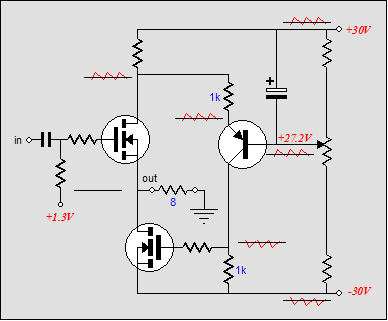
I call this circuit the Taylor source follower after P. L. Taylor, whose June 1973 article, "Audio Power Amplifier," in Wireless World, served as the inspiration for this circuit. (His amplifier used transistors and ran in class-AB.)
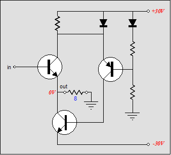
Taylor Amplifier
Of course, there is no reason that the Taylor-inpired scheme cannot be applied to tubes. Below is such an implementation.
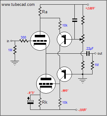
The PNP transistor is used to set the idle current through the MOSFETs. The lower the base voltage, the greater the idle current. Since we are running the buffer in strict class-A, why not exploit the non-problematic addition of a DC servo loop to automatically set the bias current. Below, we see that a second PNP transistor has been added. It senses the DC voltage across the sense resistor and adjusts its collector voltage to bring the DC voltage in line with its base-to-emitter voltage drop. In other words, we are using the transistor’s base-to-emitter voltage drop as a voltage reference and the transistor as a single stage amplifier with 100% DC negative feedback.
Alternatively, we can add a DC servo to the input, to keep the amplifier’s output in line with ground. Unfortunately, one transistor is not enough to accomplish this task, so an OpAmp will be needed, preferably a FET input OpAmp with a low DC offset and unity gain stable.
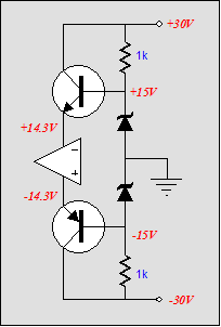
The one potential hassle we face is powering the OpAmp, as few can survive ±30 volts. The solution is to either use two voltage regulators to drop the rail voltages, or to use two transistors and a pair of zeners to achieve the same goal.
Since we began with a tube circuit, we should end with one; well, a hybrid one at least. Notice how the amplifier needed a coupling capacitor at the input, as the MOSFET’s gate needs to see a positive bias voltage. The bias voltage was 1.3 volts. This voltage could also be derived from a triode’s cathode, as shown below.
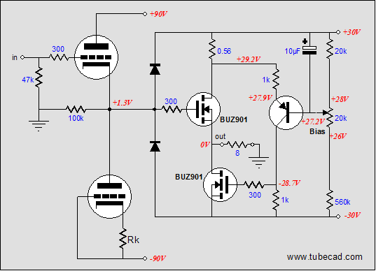 The two triodes buffer the input and provide a needed DC offset, which the bottom triode’s cathode resistor is crucial in setting. Because the two triodes are in series, the amplifier should be safe at turn on and when a tube is jiggled in its socket. The two diodes protect the amplifier’s input by limiting the input signal swing it can see. The 90-volt rails can be derived from the 30 volt power supply.
How would such a power buffer sound? My guess is fairly neutral, with a leaning towards ripe, as the triode’s curvature would be added to that of the MOSFET. A better question might be: why not forgo the White cathode follower aspect altogether and use the two triodes to both provide voltage gain and phase splitting? One such amplifier is shown below.
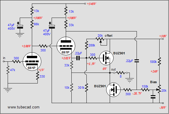
In such an amplifier, each output device works independent of each other and the need for class-A operation disappears, as class-AB is certainly possible.
|
|
|
|
Kit User Guide PDFs
Click image to download


TCJ Push-Pull Calculator
Version 2


TCJ PPC Version 2 Improvements
Rebuilt simulation engine
Create reports as PDFs*
More Graphs 2D/3D*
Help system added
Target idle current feature
Redesigned array creation
Transformer primary & secondary
RDC inclusion
Save user-defined transformer
definitions
Enhanced result display
Added array result grid
*User definable
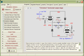
TCJ Push-Pull Calculator has but a single purpose: to evaluate tube-based output stages by simulating eight topologies’ (five OTL and three transformer-coupled) actual performance with a specified tube, power supply and bias voltage, and load impedance. The accuracy of the simulation depends on the accuracy of the tube models used and the tube math model is the same True Curves™ model used in GlassWare's SE Amp CAD and Live Curves programs, which is far more accurate than the usual SPICE tube model.
Download or CD ROM
Windows 95/98/Me/NT/2000/XP
To purchase, please visit our Yahoo Store:
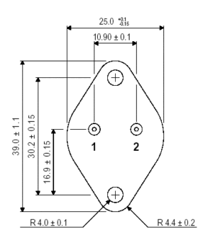
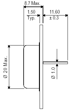
BUZ901
N–CHANNEL
POWER MOSFET
FEATURES
• HIGH SPEED SWITCHING
• N–CHANNEL POWER MOSFET
SEMEFAB DESIGNED AND DIFFUSED
• HIGH VOLTAGE (160V & 200V)
• HIGH ENERGY RATING
• ENHANCEMENT MODE
• INTEGRAL PROTECTION DIODE
• P–CHANNEL ALSO AVAILABLE AS
BUZ905 & BUZ906
POWER MOSFETS FOR
AUDIO APPLICATIONS
VDSX = 200V
VGSS = ±14V
ID = 8A
ID(PK) = 8A
PD = 125W
Tstg = –55 to 150°C
Tj = 150°C
RqJC = 1°C/W
|


