| John Broskie's Guide to Tube Circuit Analysis & Design |
07 December 2009
Super Triodes The self restraint I am speaking about is the triode's relatively low rp, that is, plate resistance. MOSFETs, transistors, JFETs, and pentodes all offer transconductance, the ability to efficiently control current conduction through an electronic device, but only the triode presents a low parallel resistance. Yes, MOSFETs, transistors, JFETs, and pentodes also present drain, collector, and anode resistance, but far too much of it. (By the way, note how “resistance” is a positive way of denoting a negative attribute. Resistance is the inverse of conductance, so a low resistance is a high conductance; high resistance, low conductance. I remember once helping a friend with his electronic project and he was conceptually stymied by the circuit. I kept saying, “It's a high resistance point there, so we can pretty much just ignore it.” But he kept hearing “It's highly resistive, highly impervious, highly defiant, highly able to oppose or retard.” He told me, “If it is a high resistance, then how can we ignore it, when its high resistance is constantly dragging us down?” Thus, we see the danger of describing a negative in positive terms. Wait a second—is such a statement shockingly close to being politically incorrect in some truly fundamental sense? I mean, more than just an unjust self-esteem reducer; rather something whose very utterance might betray too much of my niceness-deprived nature?)
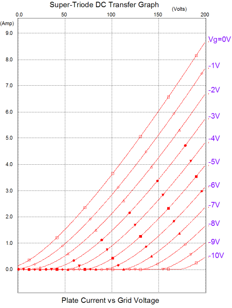
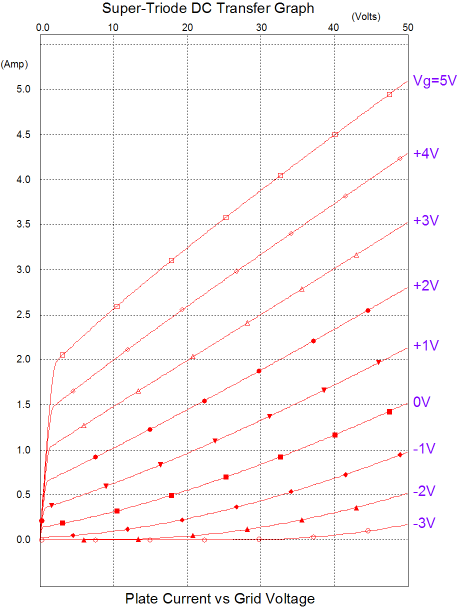
The triode's low plate resistance creates an intrinsic negative feedback loop with the triode, limiting its maximum voltage gain to its mu, which is just the product of its transconductance against its rp. But as this feedback loop exists within the electron stream itself, it is both instantaneous and integral to the triode's functioning. Much like a naturally virtuous man, the triode does not need a lot of external straightening. So, if the triode is so great, why were the tetrode and pentode developed? Triodes suffer from high Miller-effect capacitance and limited voltage gain and power output; and there are electronic uses that require wider bandwidth and greater power delivery, to say nothing of smaller size and higher efficiency. In a pure-triode world, the iPod cannot exist. Nonetheless, what we really need is a beefier triode, a triode capable of delivering several amperes of current under little cathode-to-plate voltage, a triode that is relatively cheap and widely available, and a triode that does not require gobs of heater current. Well, we can dream can't we? The following set of plate curves, the result of a SPICE simulation, shows one triode that I found that might fit this catalog of requirements.
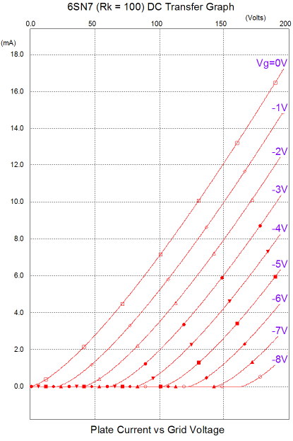
The first thing that steals our attention is the excellent linearity of the super triode; then we note that the Y-axis is labeled in amperes, not milliamps. This triode delivers three times the current at 100V that a 6C33 does, yet its heater only draws 0.6A, the same as a 6SN7—which makes sense, as the this super triode is a 6SN7. How can that be, as the 6SN7 set of plate curves looks more like this:
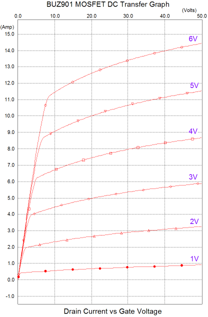
That's more like it; milliamps, not amperes. So how was this mild-mannered Clark Kent of a triode transformed into SuperTriode? The answer lies in adding a sidekick to the 6SN7, one that really kicks.
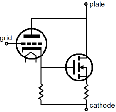
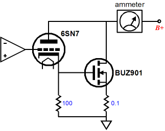
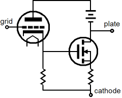
Wedding the 6SN7 to the BUZ901 N-channel power MOSFET results in a SuperTriode and the marriage is easy enough to arrange.
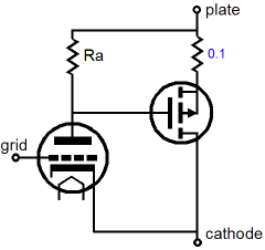
The MOSFET derives its input signal from its connection to the triode's cathode, so the triode both drives the MOSFET's gate and supplies the solid-state device's required positive bias voltage. Additionally, the triode shields the input signal source from the MOSFET's high input capacitance. Moreover, the triode imposes its flavor upon the MOSFET. Had the circuit been so arranged that the triode's grid and the MOSFET's gate were tied together, the two active devices' transfer curves would be merely summed, with the MOSFET grossly overwhelming the triode's puny efforts. But with the MOSFET gate attached to the triode's cathode and it drain attached to the triode's plate, the triode dictates the MOSFET's current conduction. For example, if the B+ voltage is increased in the circuit below, the 6SN7 will increased its current conduction, thereby increasing the MOSFET's conduction as well, far beyond what the same increase in drain voltage would incur. Conversely, if the B+ voltage falls, both the 6SN7 and MOSFET will decrease their conduction. In other words, the triode imposes a negative feedback loop on the MOSFET's current conduction. (Compare the amplification factors of of the naked 6SN7 and the SuperTriode in the graphs above; both equal 20, the mu of the 6SN7.)
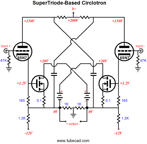
Let's take our SuperTriode and plug it into some famous topologies. The following schematic shows a Circlotron power amplifier that uses two SuperTriodes.
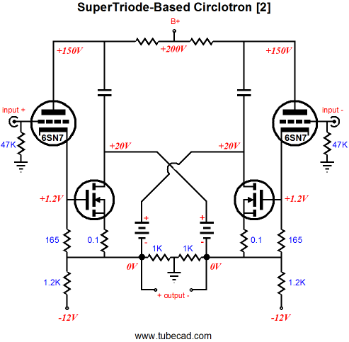
First, I must point out that to simplify the schematic I eliminated the usual (and required) grid- and gate-stopper resistors, but they must be used in reality. Second, this is an interesting hybrid power amplifier. I like how the 6SN7 controls the BUZ901 and how simple this output stage is. But then, I am also frightened by the DC coupling between cathode and gates. What happens at startup, when the tubes are cold and not conducting? What happens if a tube is wiggled in its socket? Scary stuff. In other words, I would definitely use internal coupling capacitors. Still, even with the extra coupling capacitors, this hybrid output stage seems to offer a great deal and its SPICE simulations look extremely promising. I am sure many will not see the two SuperTriodes, as the tube plates and MOSFET drains appear unconnected. Remember that the batteries shown in the schematic represent perfect voltage sources, which present no AC resistance, effectively shorting the cross-coupled capacitors to the MOSFETs' drains. Rearranging the topology makes this point even clearer.
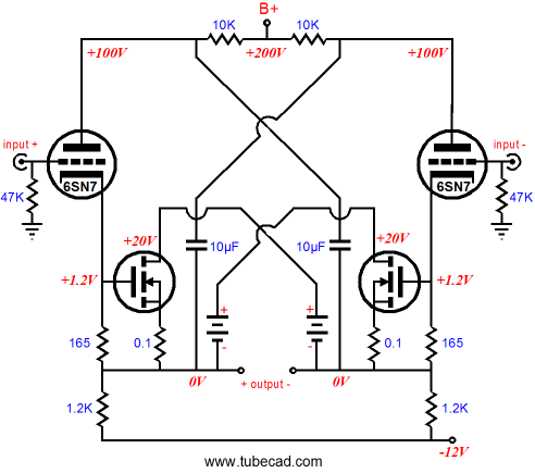
Assuming large-valued capacitors, we can readily see how, in AC terms, the drain attaches to the plate. Yes, the plate and drain see different DC voltages, but in AC terms they are tightly coupled. By the way, the two 1k resistors that attach to ground are not needed, as the 1.2k resistors reference the output to ground just as well. So why did I leave them in the above schematic? Many would not recognize the Circlotron topology without them, but for the rest of us, here is the new schematic:
What we need is a new set of plate curves for the SuperTriode, a set that would incorporate the dissimilar plate and drain voltages.
With the addition of the high-voltage battery, we can sweep the SuperTriode's plate curves at low voltages:
The set of plate curves shown above reveal the current conduction over drain-plate voltage against different grid voltages. Note that these grid-voltage plots do not represent the 6SN7's grid-to-cathode voltage, but the SuperTriode's grid-to-cathode voltage.
P-channel MOSFETs & SuperTriodes
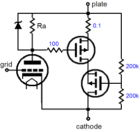
This configuration works in much the same way that the N-channel-MOSFET-based version does; the triode governs the MOSFET's current conduction. As the triode's current conductance increases and decreases, so too does the MOSFET's. If the triode ceases to conduct, so does the MOSFET. The only real problem with using P-channel MOSFETs is their low 500V upper limit on maximum drain-to-source voltage. I haven't looked, but 500V was about as high as a readily available high-voltage, P-channel MOSFET could withstand. One workaround is to cascade two or more P-channel MOSFETs, as shown below.
The two 200k resistors define a voltage divider that ensures that the two P-channel MOSFETs evenly split the available voltage. The added zener diode is a safety enhancement, which limits the maximum gate-to-source voltage that the topmost MOSFET can see, which in turn limits the maximum current conduction for the entire MOSFET string. By the way, I envision using such a SuperTriode in a single-ended or push-pull power amplifier, wherein the triode is not a wimpy 6SN7, but a 300B or 2A3 or 6AS7 or, at least, a 12B4. A fair ratio might 1 to 3, with a big triode, such as a 300B; and 1 to 10, with a small 12B4.
OTL Output Stage & SuperTriodes
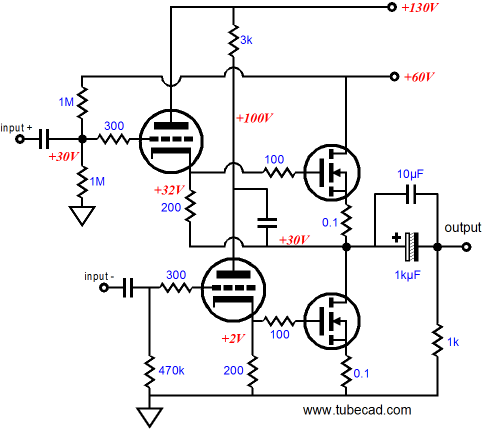
But how do we get the triode within the SuperTriode to work with only 30V of cathode-to-plate voltage? We don't and we couldn't, unless there were some buffed cousin to the 6GM8 that I am unaware of. Instead, we use two power supply rail voltages, +60Vdc and +130Vdc.
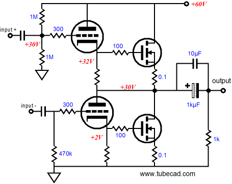
The unlabelled capacitor in the center of the above schematic couples the OTL's output to the bottom triode's plate, ensuring SuperTriode functioning of the two paired devices. Note that, at idle, both triodes see the same cathode-to-plate voltage, 100V. Also note that both triodes undergo the same peak cathode-to-plate voltage swings, but in anti-phase, as the output signal is delivers to the load. The drive signals will differ, not just by the phase inversion, but also in magnitude, as the top SuperTriode will need to see the same drive signal as the bottom SuperTriode plus the output's voltage swing. For example, it might take 1Vpk to get the bottom SuperTriode to swing 10Vpk into 8-ohms, so the top SuperTriode must see an input signal of 1Vpk + 10Vpk, in other words 11Vpk. One last point to note, both triodes equally work into the external load impedance; the unlabelled capacitor relays the bottom triode's current swings into the load, while the direct connection of the top triode's cathode resistor to the output ensures that this triode also swings current into the load. How cool! The tubes help drive the loudspeaker. So how many watts do they provide? Well, if they idle at 10mA, which would be reasonable for a 6DJ8/6922, then they will deliver 0.4mW into an 8-ohm load. What, less than 1milliwatt? Yes, that's it. Of course, if the idle current were upped to something more substantial, such as 100mA, they would then deliver 40mW; 200mA, 160mW; 500mA, 1W. In other words, the MOSFETs do almost all the hard work, while the triodes get all the credit (and ad copy). Let's now turn to a Zen-like single-ended hybrid amplifier. The amplifier in the schematic below uses a single SuperTriode. All of the MOSFET's current gain without the all the pain of a 1k input impedance.
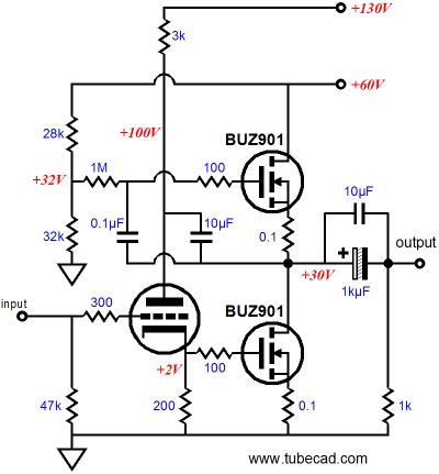
This amplifier must employ a heavy idle current of around 3A, as it is purely single-ended in functioning. In other words, it must idle at the desired peak output current swing. For when the bottom MOSFET turns off, the top MOSFET must pull up by 3A, which will develop 24Vpk across the 8-ohm loudspeaker. Conversely, when the bottom MOSFET tries to pull the output down by 24 volts, it must draw 6A, as the top MOSFET still conducts at 3A and the loudspeaker draws 3A. Contrary to what you read in the glossy magazines, class-A operation is not efficient and single-ended; and constant-current-source-loaded, class-A operation is even less so. In fact, the maximum theoretical efficiency of such an amplifier is 25%. Indeed, having just written the last paragraph, I now see that the 60V power supply rail is probably excessive and will result in too much heat. A safer and saner B+ voltage would be closer to 40V, which would yield about 16W into 8-ohm loads. By the way, the constant-current source loading can be replaced by a large choke, which will up the maximum theoretical efficiency to 50%. Another "by the way": should the above amplifier ever get built and sold, I am sure that it would be touted as being feedback-free. The amplifier, however, does make use of a feedback loop; it just happens to the triode. Without the 10µf capacitor that connects the triode's plate to the output, this amplifier's gain would equal the bottom MOSFET's effective transconductance against the load impedance. This means near infinity, when the loudspeaker is not attached. But with the triode and bottom MOSFET wedded into a SuperTriode, the amplifier's unloaded gain equals the mu of the triode used. Using a triode as a feedback loop has appeared several times in the Tube CAD Journal. Remember the following circuit from blog number 8?
The SuperTriode & GainClone
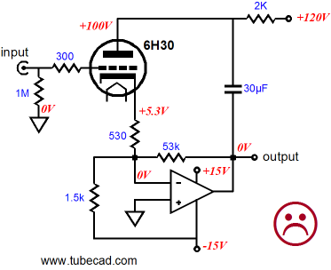
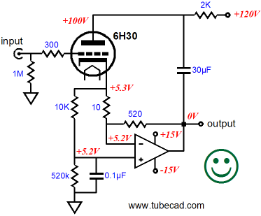
The 6H30 both receives the input signal and works as part of the feedback loop. The 1.5k resistor that attaches to the negative 15V power supply rail provides an offsetting current path for the tube, so the solid-state amplifier's output remains DC offset free. Without this resistor, the output would try to center at -530Vdc. The 30µF capacitor that bridges the solid-state amplifier's output to the triode's plate completes both the SuperTriode transformation and the negative feedback loop. In other words, this hybrid amplifier's gain is not equal to 53k/530, as you might suppose; instead, it should come in at close to the 6H30's mu. So what's not to like about this design? Although this circuit will function perfectly in a SPICE simulation, it holds one glaring problem: it isn't safe. What happens at startup or if the tube is left out of its socket? The 1.5K resistor keeps offsetting, but there is no tube to offset, so the amplifier's output swings up and locks at 15V rail. One workaround is to use a DC servo-loop instead of the 1.5k resistor. Another possibility is to use both of the solid-state amplifier's feedback resistors (10 & 520-ohms) as the triode's cathode resistor, which terminates into ground potential at the amplifier output.
The added 10k and 520k resistors work as a complementary voltage divider that ensures that the solid-state amplifier's positive and negative inputs see the same DC voltage and that the output centers at 0v at idle. (If 0.1% resistors are used, the resulting DC offset will be small enough to ignore, but with 1%, measure first, then coonect the speakers (or headphones). In DC terms the triode sees 530 and 530k resistances in parallel as a cathode resistor. In AC terms, the triode sees a 10-ohm cathode resistor, as amplifier's negative input defines a virtual ground point. Update: be sure to read blog 179 for an update on the above circuit.
Next Time //JRB |
E-mail from GlassWare Customers
High-quality, double-sided, extra thick, 2-oz traces, plated-through holes, dual sets of resistor pads and pads for two coupling capacitors. Stereo and mono, octal and 9-pin printed circuit boards available.  Aikido PCBs for as little as $24 http://glass-ware.stores.yahoo.net/
Only $19.95
Download or CD ROM For more information, please visit: |
|||


| www.tubecad.com Copyright © 1999-2009 GlassWare All Rights Reserved |