| John Broskie's Guide to Tube Circuit Analysis & Design |
| October 30 2026 | Post Number 649 |
||||
Happy Halloween!
But, amazingly enough, Amazon came to the rescue, so we now have three skeletons on our porch, cat and dog and human skeletons, albeit small ones and a huge garage-door Halloween banner—all for less than $60.
This cute painting went over so big that we now have a copycat neighbor two houses down, using the exact same banner. (Their ten-year-old son loves cats.) It took me two hours to install it; my neighbor, over three hours. It wasn't a fair race, however, as I held the advantage of not having any "helpers," whereas he had three. As there are at least another dozen cat-themed Halloween banners at Amazon, I plan on using a different one each year until we have the complete collection. One day, I will carve the triode-symbolled pumpkin, possibly using a transmitting tube, such as the 211 or 813 or 845, to provide the internal light, if the pumpkin is large enough. (Only the heater/cathode need be powered.)
Resuming Where I Left Off Almost 20 years ago in my Post 111, I came up with the DGNNAHA label (which stands in place of Dear God No—Not Another Hybrid Amplifier!), as I so disliked seeing so many lame and similar hybrid power amplifier designs in audio-construction magazines. While searching for my first mentioning of DGNNAHA, I encountered Post 291, which held the following observations:
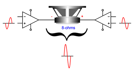
Yes, that was a dang long quote. Since pixels are effectively free, however, only a fool would be parsimonious in expending them—besides, it's fun (embarrassingly too fun) to quote oneself. Actually, I was about to leave only a link to this post, but I know that fewer than one in a hundred ever follows a link. Moreover, I am quite proud of the post. In fact, I wonder what type of coffee I was drinking when I wrote this post (Sumatran, perhaps?), as it strikes me as particularly fine. No doubt, some readers wonder which whiskey I poured into my coffee that day and further wondering what the hell do Aristotle, gratuitous nude scenes, and porn have to do with audio. My view is that you can get away with having a distinctive, if not a snappy, prose style, as long as few recognize that is what it is. This echoes Raymond Chandler's famous observation in a 1949 letter to his British publisher, Hamish Hamilton: "My theory has always been that the public will accept style provided you do not call it style either in words or by, as it were, standing off and admiring it." Wasn't I just standing off and admiring it? Indeed. The shame. Returning to audio, my latest thoughts were along the lines of using a single-ended-to-balanced, tube-based input stage and a balanced-bridge, solid-state output stage. Although the bridge output-stage configuration is what most modern class-D amplifiers use, originally it was used in class-AB output stages. The logic is: since a loudspeaker is an intrinsically differential device, why not drive it in a balanced, i.e. differential, fashion? The bridge configuration allows us to get four times the amount of power output from power-supply rail voltages than what we would get with the same rail voltages with the conventional single power amplifier. For example, with +/-24Vdc power-supply rails, a single solid-state power amplifier might swing voltage peaks of +/-20V, which into an 8-ohm load equals 25W. In contrast, two of the same power amplifiers in a bridge configuration would yield +/-40V peak voltage swings, which equal 100W into 8-ohm loudspeakers.
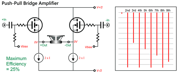
And since solid-state output devices are not current shy, the bridge configuration allows us to halve the B+ voltage, but we must double the net idle current. With the bridge configuration, current delivery is of key importance, as each amplifier effectively sees half the load impedance, 8 ohms appearing as 4 ohms, something no tube-based OTL amplifier could tolerate. What I do not like about the bridge configuration is that, like the Circlotron, it delivers a very push-pull signature, with far greater attenuation of even-order harmonics, leaving only the annoying odd-order harmonics.
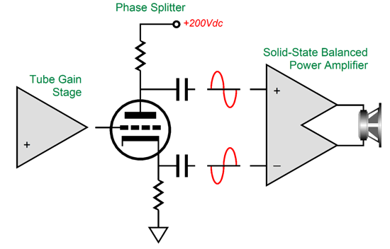
For example, this simple bridge output stage enjoys two single-ended, class-A structures—constant-current source loaded no less, but as it runs the two MOSFETs in anti-current phase, it gives rise to the severe push-pull harmonic structure. My intended workaround is to pre-flavor the drive signals with tube-based circuitry that delivers ripe single-ended harmonic signature. Here was the design's overview:
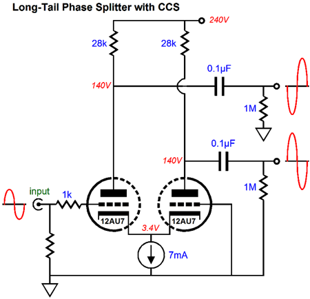
In other words, I want the tube-based frontend to purposely undo some of the balanced output stage's push-pull harmonics by introducing heavily single-ended harmonics first. Not all tube circuits can deliver the desired results, sadly. For example, a tube-based long-tail phase splitter also converts a single-ended input signal into a balanced output pair of signals, but it, too, delivers more of a push-pull harmonic structure.
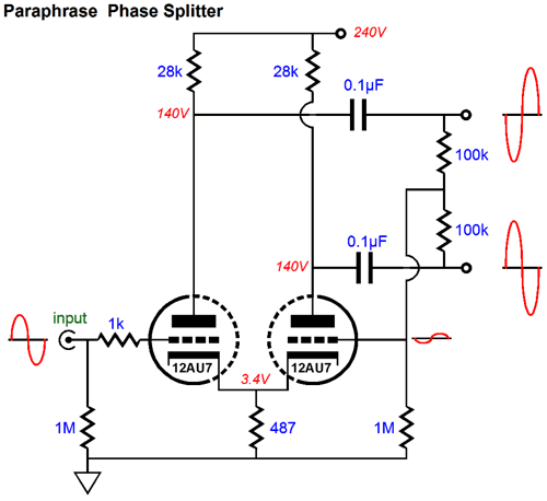
Ditto, the paraphrase phase splitter.
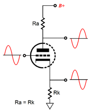
In both these circuits, the two triodes run in equal anti-current phase. In contrast, the split-load phase splitter holds only one current phase.
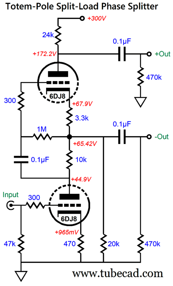
A super-intriguing variation on the split-load phase splitter is the totem-Pole phase splitter:
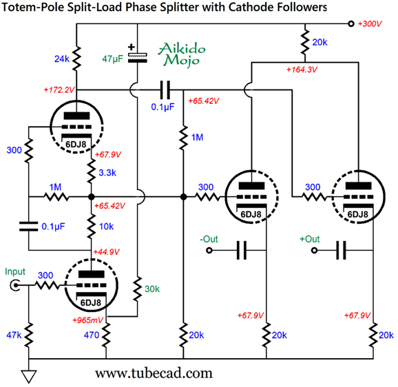
This circuit delivers a lovely single-ended cascade of harmonics. See my Post 444 for more details on its operation and the clever positive-feedback variation. Extra gain, however, is something we do not need in this application. Here is the totem-Pole phase splitter with a 6DJ8 tube and a lower B+ voltage.
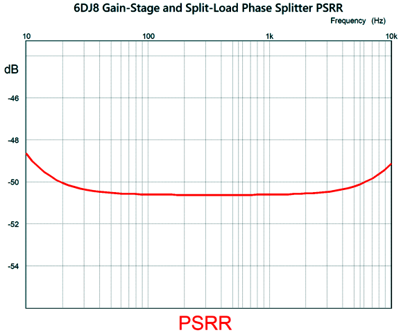
This circuit delivers a balanced output gain of 1:50 peak-to-peak (+34dB). The PSRR is poor. With the addition of some Aikido Mojo we improve the PSRR substantially.
The 30k resistor and 47µF capacitor inject enough power-supply noise into the input triode's cathode to force an equal amount of noise at each output, which the following balanced power buffer stage will ignore. When measuring the PSRR of a balanced output in SPICE simulations, we use the following method: we take the Log of the net difference between the two outputs leaked power-supply noise and multiple the resulting number by 20 to get the answer in dBs. 20 x Log(Inverting Output – Noninverting Output) If both output leak the exact same amount of power-supply noise and in perfect phase alignment, the result will be infinite PSRR, although each output might exhibit a leakage of power-supply noise of 100%. The assumption here is that the following balanced amplifier will use its high common-mode rejection (CMRR) to ignore the equal amount of identical power-supply noise riding on the output signals. (Preferably, both outputs would only contain a fraction of the power-supply noise.) We adjust the Aikido Mojo resistor's value to attain the state of equality. Here is a simpler example of adding an Aikido resistor.
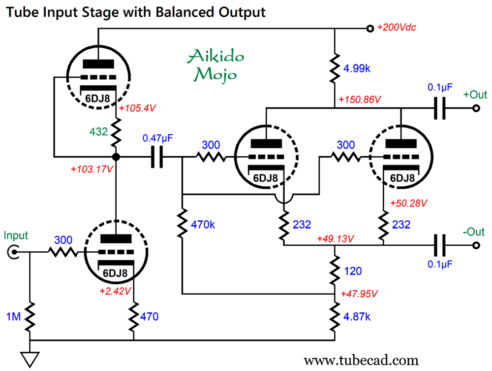
Without the Aikido Mojo, the PSRR is a poor -9.6dB at 100Hz. (By the way, this circuit delivers a lovely single-ended harmonic structure.) This Aikido Mojo technique differs from the approach I used in the circuit from my last post:
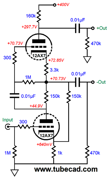
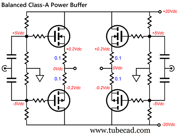
The Aikido Mojo is found in the 432-ohm cathode resistor value. In SPICE simulations, I discovered that this value brought the phase splitter's two outputs into alignment. By the way, since this circuit uses a lower B+ voltage and delivers lower gain, it will work better within a lower powered hybrid power amplifier or power buffer. For example, here is a suitable 60W class-A bridged output stage.
Each MOSFET idles at 2A, which implies a peak output current swing of 4A, which further implies 64W of output into an 8-ohm load. Yet, this balanced power buffer runs off only ±20Vdc power-supply rails. Mind you, at idle this output stage dissipates 160W, so its efficiency is only 40%. Class-A isn't cheap. Another possible circuit is the Circlotron.
Circlotron Circuits
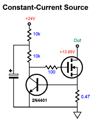
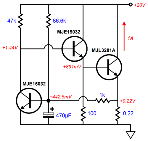
The 0.47-ohm resistor senses the current flowing through the MOSFET. The 2N4401 NPN transistor provides both the voltage reference in the form of its emitter-to-base voltage drop and the needed DC gain stage. If the MOSFET draws too much current, the transistor's current conduction increases, causing its collector voltage to fall, thereby lowering the MOSFET's gate voltage and current conduction. Negative feedback in a nutshell. Of course, we could get more elaborate by using an IC tight-tolerance voltage reference and an OpAmp to set the MOSFET's gate voltage, but the single transistor is compelling due to its simplicity. Unfortunately, its emitter-to-base voltage drop is a bit too high. My workaround is to add a resistor to the B+ voltage to create a lower effectively voltage reference. In the following example, the current-sense resistor voltage drop is only 0.22 volts.
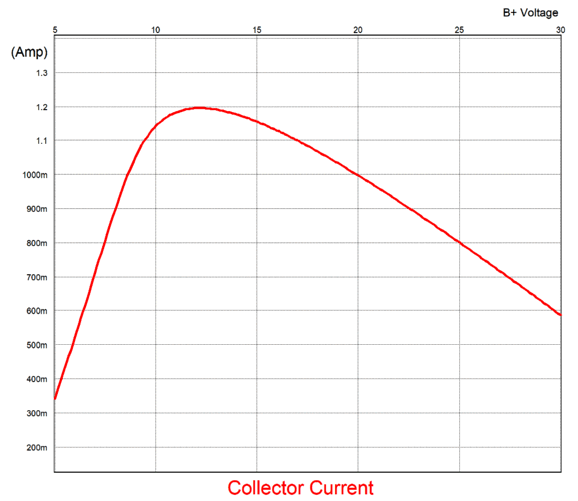
The leftmost MJE15032 NPN transistor's base still sees 0.443Vdc. Note that if the B+ voltage is increased, the idle current through the MJL3281A decreases, which is quite desirable in an output stage. Here is the graph that shows the current flow versus the B+ voltage.
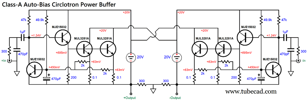
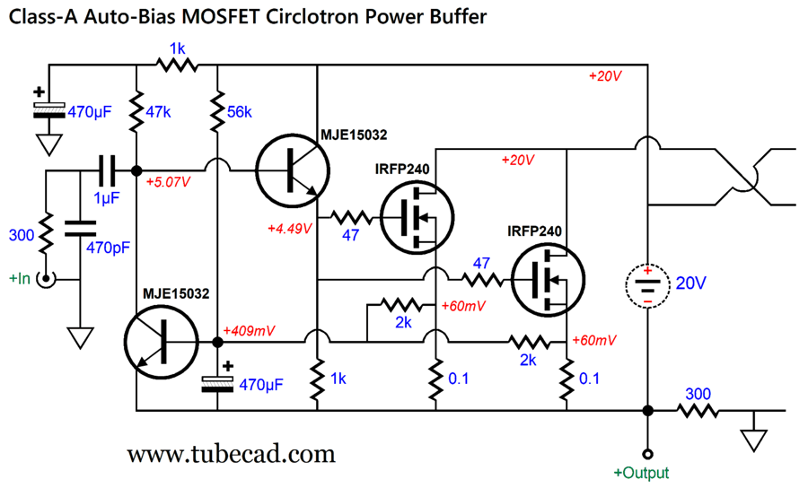
Ideally, we would get a straight line whose slope would ensure constant-power dissipation by the MJL3281A, but the decline current flow beyond the nominal 20Vdc B+ voltage is a feature. Here is a power buffer Circlotron based on this auto-bias configuration.
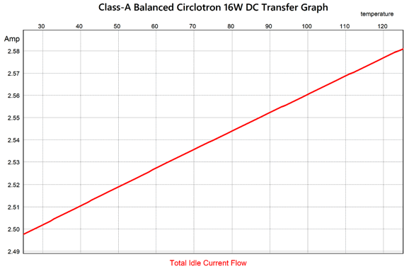
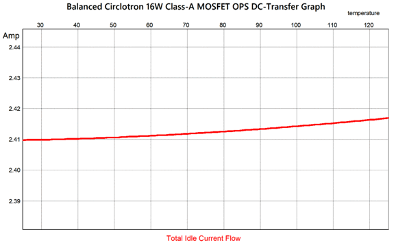
The 20Vdc floating power supplies and the idle current flow of 1.26A per side, along with the necessary voltage overhead required by the transistors, limits the power output to only around 16W for 8-ohm loads. This puts the efficiency at about 32%, 18% short of the theoretical maximum of 50% for strict class-A operation. Of course, if we up the number of output transistors and increase the floating power supply voltage, we can get far greater power output. The big question here is, how well did the auto-bias feature work? Very well indeed:
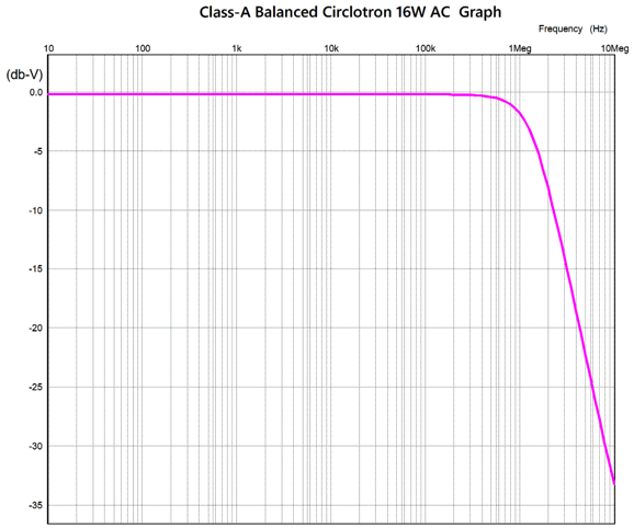
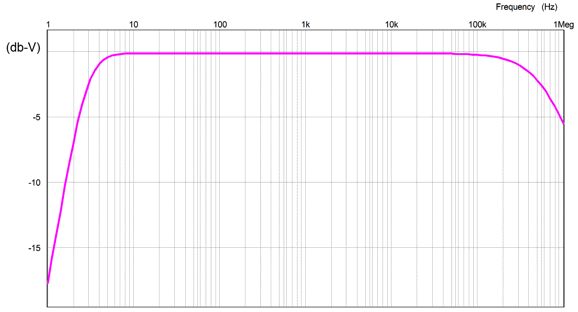
In this SPICE simulation, I varied the output transistors (MJL3281A) temperature from 25C to 125C, yet the total idle current flow increased by less than 10mA. Excellent. The next SPICE test I ran was the frequency response test.
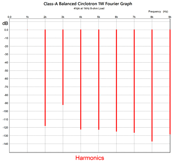
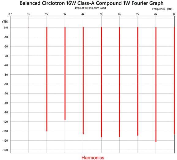
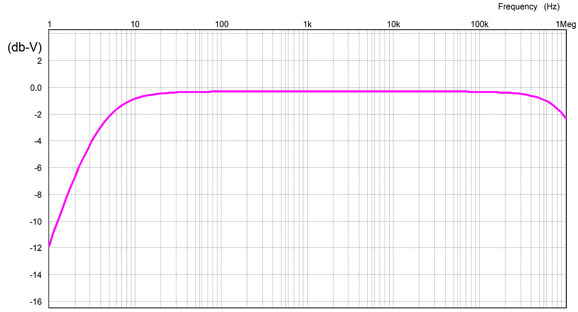
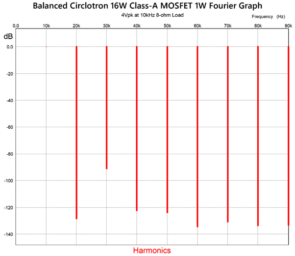
With a -3dB high-frequency cutoff beyond 1MHz, we needn't worry about bandwidth. By the way, the Circlotron actually exhibits a gain of 2 (6dB). Well, what about distortion? At 1W of output, the Fourier graph doesn't look too bad.
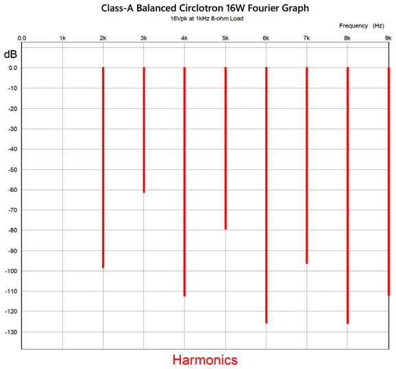
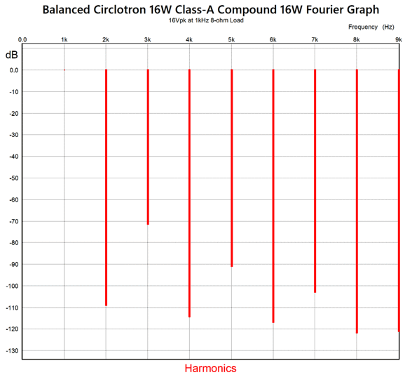
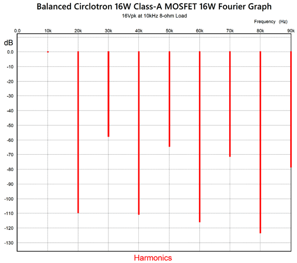
In fact, its crazy good for a feedback-free circuit, save for the relatively higher 3rd harmonic. At full output, 16W, the push-pull harmonic structure reveals itself.
The THD is around 0.1%, but all the tasty even-order harmonics are greatly suppressed, leaving the irritating odd-order harmonics overstressed, creating the typical push-pull sound. Will the tube-based frontend be enough even-out the harmonics? Perhaps. My next idea was to include some negative feedback in the design by using a compound circuit.
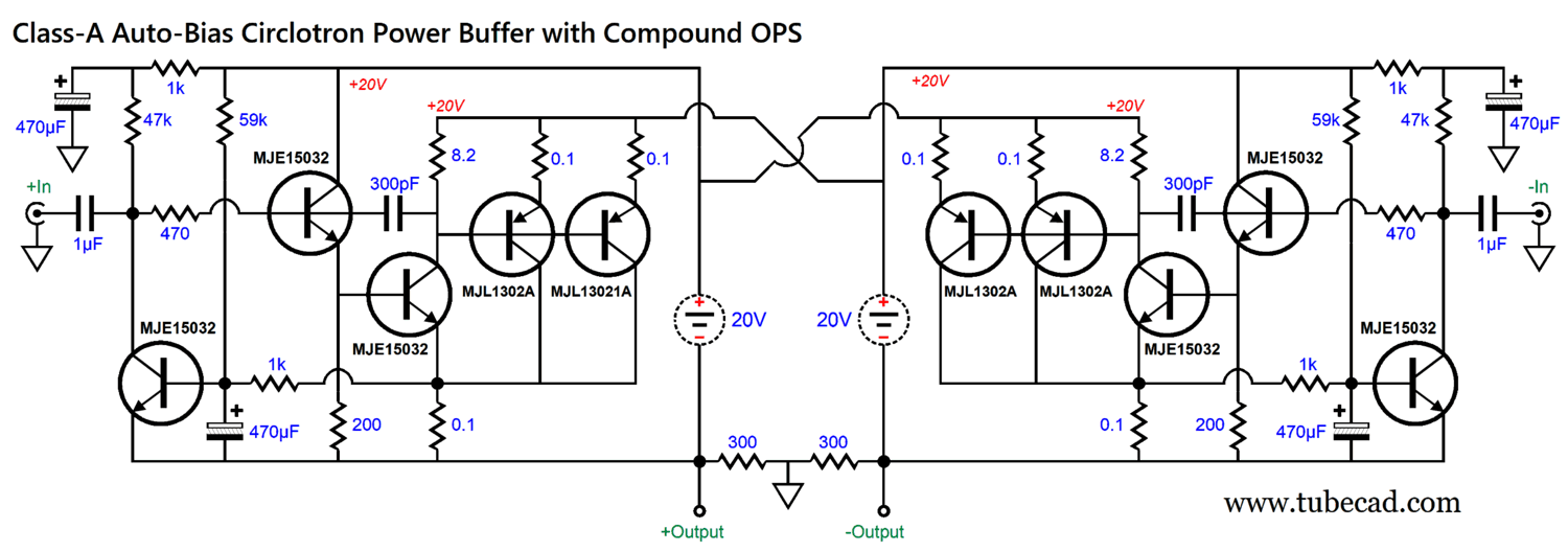
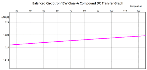
The compound configuration places the PNP transistors under the control of an NPN transistor, thereby greatly increasing the linearity, but at the cost potential high-frequency instability and rougher clipping. In addition, it works best in class-A operation, as the transition between output devices in class-AB mode are sharper. On the other hand, the compound configuration is itself a form of auto-bias, as long as the controlling transistor is thermally isolated from the output transistors. The following SPICE-generated DC-transfer graph reveals the tighter auto-biasing.
In spite of a span of 100C, the idle current increases by less than 2mA (the graph shows only one side, not the total). The Fourier graph also displays an improvement.
Yes, the THD is improved, and the 3rd harmonic is further suppressed, but look at the 4th harmonic up to the 9th. They are worse. The negative feedback made these worse, but did decrease the output impedance and improved the auto-biasing. at full output, thing actually look better.
All the odd-order harmonics are further suppressed by 10dB compared to the first Circlotron. But as I had to place a capacitor at the controlling NPN transistor's collector to ensure high-frequency stability, the high-frequency bandwidth is truncated a bit.
Thus, I concluded that the compound arrangement was not the answer, in spite of some of its features. My next idea was to try output MOSFETs in place of the output transistors.
If nothing else, MOSFETs are far more robust than bipolar transistors in actual use, as they survive when their bipolar brothers go up in smoke. They are also cheap and modern production has improved to the point that they pretty much come pre-matched right out the shipping tube. I did worry, however, that their relatively high input capacitance would too greatly limit their high-frequency bandwidth.
With bandwidth beyond 1MHz, no worries were justified. Next, we test the auto-bias feature.
Certainly, good enough. Now the Fourier tests.
Surprisingly enough, the harmonic structure at 1W of output pretty was much is identical as the first Circlotron with bipolar transistors. At full output, the push-pull harmonics blossom and the results are actually worse than the first version.
Bummer. Or are they actually all that bad? Note that the 10kHz test tone frequency, not the 1kHz test tone used with the other variations. Okay, what to do? How about adding an OpAmp to the mix?
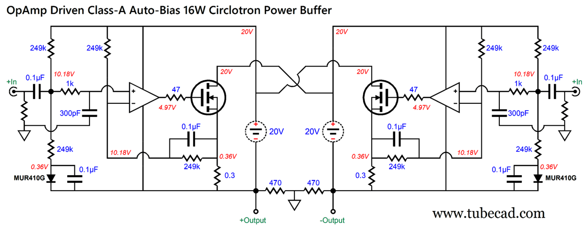
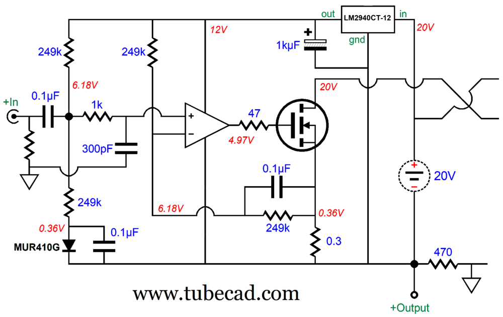
To make the OpAmp happy, I have lifted the input signal DC reference to half of the OpAmp's power-supply voltage (10.18Vdc). Why does this make the OpAmp happy? Ideally, the input voltage should cut the entire power-supply voltage in half, so 0V with a pips and 1/2 with a monopolar power supply, as the input stage needs all the voltage headroom it can get. Not so with a perfect OpAmp, but perfect OpAmps do not exist. The MUR410G rectifier is used as the voltage reference. With such trivial current flow through the rectifier, the voltage drop is a mere 0.36V. By the way, I used the four 249k resistors to prevent the use of 5% or 10% 240k resistors by readers, as we do not want a DC offset at the output terminals for the loudspeaker. (The two 0.3 resistors should be tightly matched, for the same reason.)The way we sidestep the potential DC offset is to have both halves of the Circlotron draw the exact same amount of current draw. I used the OPA2107 and IRFP240 SPICE models in my simulations. The auto-bias feature works, as a flat line developed in the temperature sweep. Next comes the frequency response plot.
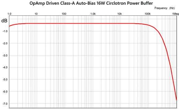
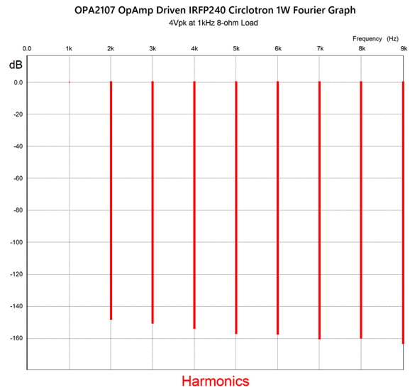
Why is there slightly less than unity-gain output? Note where the negative-feedback loop terminates, not at the outputs, but at the 0.3-ohm source resistors. The loudspeaker sees the two resistors effectively in series, which cause a slight insertion loss. Why not terminate the 0.1µF capacitors at the outputs? I tried that first, but it resulted in higher distortion. Speaking of distortion, here are the results for 1W of output.
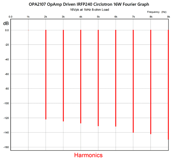
Okay, that's stunning. No doubt, too stunning. But if we assume a one hundredfold amount of too good, it is still stunning. At 16W of output, it worsens, but only by a tad; moreover, we do not see the push-pull harmonic structure.
Mercy! That's fine. Since it is impossible for me not to seek further improvements from any circuit, one idea I had was that we could give the OpAmp a regulated B+ voltage.
The 12V voltage regulator cleans up the B+ voltage and works as an intrinsic current limiter on the output MOSFETs, as it limits the potential positive output voltage swing from the OpAmp. Of course, an RC filter and zener could be used configured as simple shunt regulator. In addition, the 12V might need to be replaced by a 15V regulator or an LDO adjustable regulator, such as the LM1086. By the way, the OpAmp must be unity-gain stable. If we want more output power, we must increase the floating power supply voltage. With 48V floating power supplies, we can easily get 100W into an 8-ohm loudspeaker. The total idle current, however, must exceed 5A. Switch-mode power supplies with 48Vdc output voltage are readily available. Each should be able to deliver at least 3A of current. This would leave the heatsinks as the most expensive component of the amplifier, save for possible NOS tube purchases.
In contrast, building conventional following power supplies is made easier by most toroid power transformer holding two secondaries. For the 16W version, a 100VA transformer with two 15Vac secondaries should work well. The tube-based front end will need its own power supply, but as it draws so little current, a 30VA toroid would be massive overkill. By the way, I assume monobloc construction here.
Music Recommendation:
The Haden Triplets, The Family Songbook
If you expect something out there, avant-garde, experimental based their father being Charlie, you will be wrong, as the album is very traditional folk-country-Americana. But a hint of the jazz tradition appears in their cover of Kanye West's song, Say You Will. (Not Foreigner's song of the same title.) Jazz, like America in the past, often takes the discarded, the forgotten, or trivial and transforms it into something magical. Nina Simone's fabulous cover of "I Put a Spell on You" is a great example. It was written and first recorded by Screamin' Jay Hawkins in 1956. Give the original a listen and hear hers, and you will instantly realize her genius. The song, "Say You Will," is about calling an ex-girlfriend to come over to have sex, but she doesn't show up. The Haden Triplets cover transmutes the song into something achingly heartfelt and mournful. Magic. Since three singers sing, we should be able to hear three voices, making this album a good test of our systems.
//JRB
Did you enjoy my post? Do you want to see me make it to post 1,000? If so, think about supporting me at Patreon.
Adobe AI Summary: Here are the main points from the document: Halloween Introduction
Hybrid Amplifier Design Philosophy
Design Approaches and Technical Solutions
Practical Construction Notes
Music Recommendation
This summary captures the technical focus on improving hybrid amplifiers by thoughtful circuit design and the balancing of tube 'musicality' with the efficiency and power of modern solid-state electronics.
|
I know that some readers wish to avoid Patreon, so here is a PayPal button instead. Thanks. John Broskie
John Gives
Special Thanks to the Special 89 To all my patrons, all 89 of them, thank you all again. I want to especially thank
I am truly stunned and appreciative of their support. In addition I want to thank the following patrons:
All of your support makes a big difference. I would love to arrive at the point where creating my posts was my top priority of the day, not something that I have to steal time from other obligations to do. The more support I get, the higher up these posts move up in deserving attention.
If you have been reading my posts, you know that my lifetime goal is reaching post number one thousand. I have 351 more to go. My second goal was to gather 1,000 patrons. Well, that no longer seems possible to me, so I will shoot for a mighty 100 instead. Thus, I have just 11 patrons to go. Help me get there. Thanks.
New URL of the GlassWare Store website |
||||









| www.tubecad.com Copyright © 1999-2026 GlassWare All Rights Reserved |