| John Broskie's Guide to Tube Circuit Analysis & Design |
| 24 May 2014
DGNNAHA, Once Again Because the SRPP-input-stage-MOSFET-output-stage hybrid is so simple, so obvious, for the last four decades it has been constantly reinvented by earnest audiophiles who imagine that they have discovered the Holy Grail of audio: all the sweetness and fluidity of vacuum tubes and all the heft and command of solid-state devices. The entirely expensive sounding results of wedding a little bit of expensive glass with a lot of cheap silicon. If only. Possibly the saddest short phrase in English. (The disillusioned defense attorney laments, "If only my clients weren't so guilty." Yes, indeed, if only.)
Thus, DGNNAHA stands in place of Dear God No—Not Another Hybrid Amplifier! Imagine that a friend tells you that he is writing a great novel that—brace yourself—tells the story of a prostitute who, surprisingly enough, has a heart of gold; or a fabulously new story about two policemen, partners, one of whom is super nasty and the other, amazingly enough, super nice; or a radically new story about how a teenager's parents don't understand him... A cliche becomes a cliche because many like it. Some start life as a raw, powerful utterance, such as "she wore her fingers down to the bone," a gripping, horror-filled image, which when first voiced must have shocked and sickened: the image of white bone protruding through red, torn flesh. No more. Like the five-year old Time magazine in your dentist's waiting room and like an old worn-out 6SN7 that refuses to move the tube-tester's meter, it is now bereft of all vitality and vigor. Other cliches, in contrast, begin as garbage and continue as garbage, such as "There's a fine line between genius and insanity." Was Aristotle, Leonardo, Shakespeare, or Johnny Von Neumann insane? Alas, for the cliche, no fine line existed. Indeed, I am more likely to believe that there's a fine line between stupidity and insanity, having encountered that strange muscular, all-defiant stupidity that is not born of ignorance and timidity, but of supreme certainty and self-confidence. Prisons and insane asylums brim with those chock full of high-self-esteem. Well, in my view, the SRPP cascading into the MOSFET output-stage is just that kind of electronic cliche, as obvious as it is wrong. We deserve better. The Hollywood legend, Samuel Goldwyn, put it best: "Let's have some new cliches." I wholeheartedly agree, but with some conditions of satisfaction. "Conditions of satisfaction," what the hell is that? Simply put, conditions of satisfaction (COS in its legal acronym) are the criteria—the standards, benchmarks, guidelines, requirements, principles—that a new hybrid amplifier must pass in order to bypass the getting the shameful DGNNAHA label. Here is my list:
Wow, John, wouldn't that list kill all the fun? In one of the few lovely passages in Immanuel Kant's writings, we find “The light dove, in free flight cutting through the air, the resistance of which it feels, could get the idea that it could do even better in airless space." The poor bird does not realize that without air resistance, it would plummet to the ground. Only the mentally flabby fear the resistance imposed by rules. And surely, this list is not too onerous. Tubes should never be expensive replacements for LEDs. You know the unease you feel, if only subconsciously, when you are watching a movie which holds a gratuitous nude scene, a scene unnecessary, unwarranted, and unjustified by the film's story, serving only as a sneaky showcase for the leading lady's pert breasts and rollickingly round rump. Well, that is the sort of unease I feel when I see tubes being used gratuitously. Tubes that replace resistors needlessly; tubes that could be (and probably should be) replaced by a FET or transistor. Thus, if a tube appears in a hybrid circuit it must do something meaningful, not just lend a glowing, glistening luster to an otherwise dim, dull effort. On the other hand, there is the topic of tube porn, wherein tubes, used often superabundantly or whimsically, are the point, the whole point, the only point. In porn, nudity and sex are never gratuitous; they are essential, and plot and character development would seem gratuitously out of place. John Atwood and Christian Rintelen and I have had interesting discussions on this topic of tube porn, the outlandish display of vacuum tubes, for the sake of glowing glass, not necessarily sonic glory. I am much more disposed to greet tube porn with a smile because it is at least honest, something the serious film with gratuitous sex or nudity is not. In addition, in tube porn, cheap solid-state devices are never added to lower the price; indeed, the greater the expense, the closer to an all-tube lineup, the more decadent and opulent the results. What happens at start-up, when the cathodes are cold and not conducting, does the hybrid amplifier's output slam to a power-supply rail, thereby toasting your expensive speakers. Never forget that tubes only become an active part of a circuit when their cathodes are hot. What happens if a tube is wiggled or loses contact with its socket? Safety first, second, and last. A hybrid amplifier that puts out 1W and draws 1,000 watts from the wall socket should be tied to a chain and used as an anchor. A hybrid amplifier that could put out 40W, based on its power-supply voltages, but only puts out 10W should be ignored. A hybrid amplifier whose bandwidth only extends to 8kHz is a joke best not retold. A hybrid amplifier that claims to be a voltage amplifier—but requires 6Vpk of input signal to put out its 40W—is a poor design. (In contrast, a unity-gain power buffer that put out 40W and required a 25Vpk input signal, would be a good design.) Wouldn't it be something to use thirty 6SN7 tubes a single power MOSFET to put out 1W be something? Yes, it would be a waste of time and effort. A hybrid amplifier that relies on strikingly odd or unusual features to steal our attention is just as much a thief as the young man who has died his hair Day-Glo green or punctured his cheek with brass rivets, for neither has honestly earned our attention.
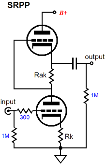
I was tempted to add a fifth rule, No SRPP stages, but I must admit that it is conceivable an SRPP stage might somehow, somewhere prove useful in a hybrid amplifier—but I have yet to see it. Still, it might be possible. Listen, John, I just don't get why you do not accept the fact that the SRPP circuit is perfect; everyone on the web thinks so. In my defense, I will point out that it is likely that I was experimenting with SRPP circuits before you were born, as I built my first SRPP effort back in about 1978, while in college. When I was a child, I spoke glowingly of SRPP circuits, I built SRPP projects, I thought the SRPP topology perfect; but when I became a man, I put away SRPP designs. Although the SRPP does have its limited uses, such as driving low-resistance loads, not reactive loads, in push-pull fashion, in general its chief feature is that it appeals to lazy minds, who find the irksome problem—what to do with the second triode in the tube envelope—solved by the SRPP. It is the quick, easy, and dirty solution to doing something with that pesky extra triode. More expansive minds can and do find better uses for the extra triode. The quick test to reveal a gratuitous or lazy use of an SRPP is: Does the SRPP actually put out power, does it swing more than its idle current into its load? If not, then the SRPP is being misused.
What is a Hybrid Amplifier? A hybrid might be partially composed of passive devices, such as an output transformer. A good friend of mine is convinced that clipping behavior is, although largely ignored, the sonic elephant in our listening room. He has concluded that transformer clipping is more sonically benign than tube or transistor clipping, so he has built tube amplifiers that purposely used a small 15W output transformer with a big tube output stage capable of delivering 60W. Perhaps, a hybrid design that used a tube frontend and a MOSFET output stage that coupled to the speaker through a rather smallish output transformer would prove worthwhile.
Triodes and MOSFETs in Parallel
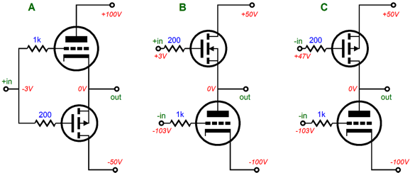
All three are interesting. Arrangement A has made an appearance here before, in blog number 214.
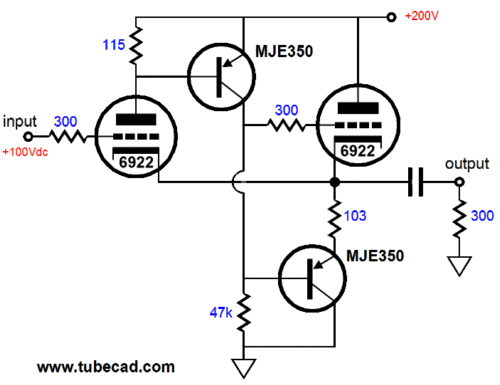
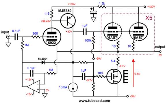
Although a PNP transistor was used below the rightmost 6922 triode, a P-channel MOSFET could have been used. Indeed, one was used in the following schematic from that post. I have been thinking about this hybrid topology lately. It's interesting, although it might fail rule 2 and surely rule 3, being neither entirely safe nor free from poor performance issues. DC coupling is dangerous with tubes and particularly with hybrid power amplifiers. What happens to the speaker, if the 6922 input tube is pulled or wiggled in its socket? I would hate to find out. (The DC servo might save the day via the the 1N4001 rectifier, but then it might be too late.) How many watts can the output stage deliver with a 5.4-ohm source resistor? Not nearly as many as the -60V power-supply rail might imply, as this large-valued resistor steals 5.4/(5.4 + 8) or 40% of the output power. With a 4-ohm speaker, it steals more than 50%.
So is this design irredeemable? No, I don't think so. The 5.4-ohm source resistor was used to weaken the MOSFET's transconductance to the level offered by the ten 6AS7 triodes in parallel. In the following schematic, we see two ways used to reduce the MOSFET's transconductance: the 1-ohm source resistor and the two-resistor voltage divider (14.3k & 10K) that throws away some of the P-channel MOSFET's input signal, effectively reducing its transconductance.
Because eight 6AS7 triodes are used in parallel, the eight 10-ohm cathode resistors are effectively in parallel, so the effective resistance is only 1.25 ohms, which against the peak current draw of 4A, equals a peak voltage drop of 5V. In turn, the the same 4A against the 1-ohm source resistor equals a 4Vpk voltage drop. In other words, in spite of these two resistances, we should easily be able to get ±32Vpk into an 8-ohm load, which equals 64W. Not bad for only four 6AS7 tubes per channel. Okay, we just passed rule number three, no huge compromises in performance, but what about rule two, the safety issue? Note the DC servo loop based on the OpAmp. It both works to eliminate any DC offset from the output and to ensure that he MOSFET draws the same amount of current as the the eight 6AS7 triodes do. Well, what happens if the triodes are missing from their sockets? My hope is that nothing bad occurs. The DC servo will still control the BUZ906 MOSFET, adjusting its gate voltage to prevent a DC offset. Even without the triodes, the BUZ906 will see a current path to the B+ voltage, through both the 10.5k and 10k resistors. In other words, I think we are safe. In contrast, the previous hybrid also used a DC servo, but its servo directly controlled the 6922's grid, and then indirectly controlled the output MOSFET's gate via the 6922 and the PNP transistor and the 1N4001 rectifier, which made me nervous.
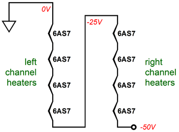
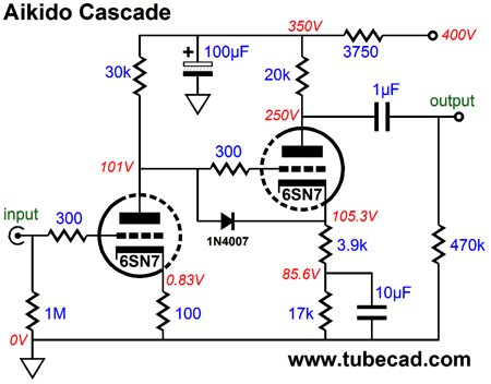
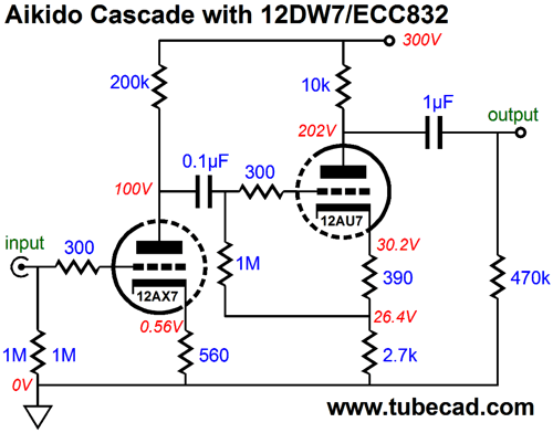
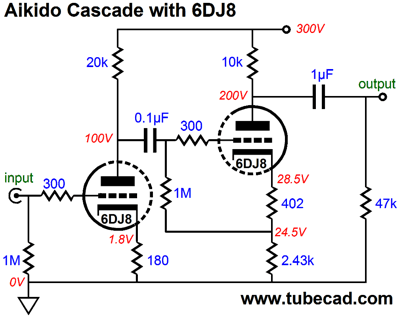
Using four 6AS7 tubes per channel is not as arbitrary as it may seem. My idea was that that a stereo amplifier could be built that held eight 6AS7 tubes, with all eight heater elements stringed up in series and placed across the -50V power-supply rail, each heater getting 6.25Vdc. Note that no phase splitter is required in this design, as the P-channel MOSFET and 6AS7 output triodes see the same signal phase; indeed, the same input signal. This would make the input stage far easier to design. A near infinite number of possible input stages could be devised. One possible design would be the Aikido Cascade circuit.
The above circuit only delivers a gain of about 56, so no negative feedback loop could be employed, bridging output to input. By switching to a 12DW7/ECC832/7247 dissimilar, dual-triode tube, we can get a gain closer to 140 and still enjoy an excellent PSSR figure. The 12AX7-based input stage leaks a third of the B+ ripple in phase to 12AU7's grid, whereupon the 12AU7's inverting gain roughly equals negative three, thereby nulling the power-supply noise that the output, as 1 - (0.33 x 3) = 0. Magic to most. Simple math for those in the know.*
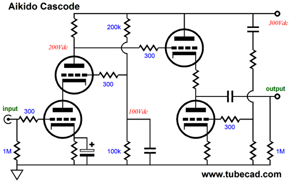
On the other hand, an Aikido Cascode could easily produce enough signal gain to drive a negative feedback loop.
A 6DJ8 input tube and an ECC99 (or 12BH7 or 5687) output would do the job quite well.
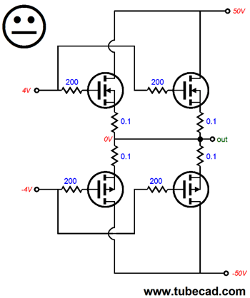
MOSFETs in Parallel vs in Series The BUZ906P is a lateral MOSFET that is both rare and expensive, whereas the IRFP9240 is both common and cheap. Since the BUZ906 is in control of the current flow through both MOSFETs, we can save by using the two different MOSFETs in series. On the other hand, if they had been placed in parallel, both would have to be the same high-quality lateral types, preferably matched devices. In addition, we would double the input capacitance, not a good idea, as the MOSFETs already present a heavy capacitance load.
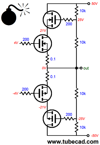
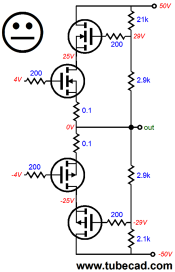
Okay, so let's place the MOSFETs in series. Are we done? No. We still face a potential problem, which the bomb symbols signifies: limited power output. Don't see how that is possible? Well, look at the following schematic and tell me what's wrong.
The two-resistor voltage dividers evenly split the rail voltages, true enough. But do the MOSFETs in series evenly split the rail voltages and what is the maximum voltage output swing that the above output stage can muster? The answers are that the MOSFETs do not evenly share the rail voltage and that output can only swing up about 40Vpk, as two-resistor voltage dividers cannot deliver an output voltage greater than the rail voltage. A big problem. The easy and inadequate solution is to alter the voltage divider resistor values, so the each MOSFET gets an even share of rail voltage.
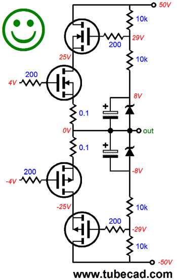
Looks great, so why is it inadequate? The problem of equal dissipation was solved, but not the problem of unnecessarily limited output swing. To solve this second problem, the following variation is needed.
The 8-volt zener diodes were chosen to equal twice the gate-to-source voltage of the topmost and bottommost MOSFETs. The large-valued electrolytic bypass capacitors will charge up to 8Vdc; and when the crescendo hits, they will be able to swing the pair of two-resistor voltage dividers output voltages beyond the power-supply rail voltage, which will allow the MOSFETs to swinger bigger output voltages. This workaround works well with music reproduction, but will begin to fail at steady sine waves, as the electrolytic capacitors will begin to loose some of their charge.
* Well, Actually
The second grounded-cathode gain stage develops a gain of on 2.5, not the 3 that the first approximation predicted. The reason it is less than 3 is that 100% of the power-supply noise did not appear at the output, only 76% did, so less inverting gain was needed to null the noise. Additionally, the first stage does divide the DC B+ voltage to a third, but not the AC voltages riding on the B+ connection; instead, it leaks 30% of the ripple, not 33%. By the way, the PSRR is extremely fine, coming in at about -60dB in SPICE simulations. The gain is a bit too low for use as an OTL frontend, as it is only about 54 (+34.6dB), but this circuit might make a fine tube microphone preamp. Do not get the idea that since the circuit displays a fine PSRR you can ignore the power supply altogether; you cannot. The Aikido Cascade circuit makes you work lighter, but you still have some work to do.
Next Time
For those of you who still have old computers running Windows XP (32-bit) or any other Windows 32-bit OS, I have setup the download availability of my old old standards: Tube CAD, SE Amp CAD, and Audio Gadgets. The downloads are at the GlassWare-Yahoo store and the price is only $9.95 for each program. http://glass-ware.stores.yahoo.net/adsoffromgla.html So many have asked that I had to do it. WARNING: THESE THREE PROGRAMS WILL NOT RUN UNDER VISTA 64-Bit or WINDOWS 7 & 8 or any other 64-bit OS. I do plan on remaking all of these programs into 64-bit versions, but it will be a huge ordeal, as programming requires vast chunks of noise-free time, something very rare with children running about. Ideally, I would love to come out with versions that run on iPads and Android-OS tablets.
//JRB |
I know that some readers wish to avoid Patreon, so here is a PayPal button instead. Thanks. John Broskie
Kit User Guide PDFs
E-mail from GlassWare Customers
High-quality, double-sided, extra thick, 2-oz traces, plated-through holes, dual sets of resistor pads and pads for two coupling capacitors. Stereo and mono, octal and 9-pin printed circuit boards available.  Aikido PCBs for as little as $24 http://glass-ware.stores.yahoo.net/
Support the Tube CAD Journal & get an extremely powerful push-pull tube-amplifier simulator for TCJ Push-Pull Calculator
TCJ PPC Version 2 Improvements Rebuilt simulation engine *User definable
Download or CD ROM For more information, please visit our Web site : To purchase, please visit our Yahoo Store: |
|||


| www.tubecad.com Copyright © 1999-2014 GlassWare All Rights Reserved |