| John Broskie's Guide to Tube Circuit Analysis & Design |
| September 16 2026 | Post Number 647 |
||||
Mental Time Travel
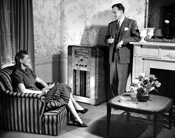
Unlike previous amplifiers that were designed to power headphones, this one could power loudspeakers. The new balanced amplifier, i.e. the push-pull vacuum-tube amplifier topology, was based on the 1915 patent for the push-pull amplifier by Edwin H. Colpitts. Now imagine that you are asked to explain what a push-pull power amplifier is, and how does it work. Good luck. It's hard enough to explain how a single-ended amplifier works, but you must now also include phase splitter circuits and center-tapped output transformers.
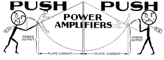
After a slow start, push-pull amplifiers became popular; for example, six years later, 1932, Radio News magazine publishes an article titled, "Class-B Tubes—Their Significance in Future Audio Amplifier Design," and Radio-Craft magazine offered their article, "Push-Pull Power Amplifiers," by C.H.W. Nason, both of which complicate the push-pull operation issue further, as you must now not only explain anti-phase signals, but rectified anti-phase signals, as class-B entered the picture. The following image is from the Radio-Craft article.
Imagine looking at this image and being told that's how a push-pull amplifier works. Let's see, a boy on a swing is pushed, and at the other end of his travel he becomes a ghost, where another demon consumes his soul. Yeah, I get it. What was the point behind this mental time traveling? The new, even when simple, is often difficult comprehend. In other words, this trip was necessary to make our minds a bit more flexible before moving on to the next topic.
Broskie Amplitude-Staggered Active Crossover I asked Gemini to evaluate the circuit:
I know all too well that there is much to hate about artificial intelligence, but—dang it—that was a fine capsule summary. (I didn't use the word "brunt" in my post, but I wish I had. Nice job, Gemini.) We do not presently say, but we soon will say: Good stuff in, good stuff out. (Or, some others might put it: Platinum in, Platinum out.)
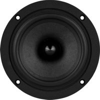
We are not limited to subwoofers, as the amplitude-staggered circuit can be used with fullrange drivers. A single fullrange driver wonderfully approximates a point-source of acoustic radiation.
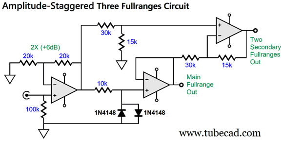
With no crossover and, thus, no concomitant phase shifts and lobbing effects, the fullrange driver presents a seamless sonic presentation, so unlike the jigsaw-puzzle sound-picture produced by a four-way loudspeaker. "But, John, a two-way speaker is better than one fullrange driver, just as a three-way speaker is better than a two-way; a four-way, better than a three-way… Everyone knows this." Do they? I remember a friend extolling the sound from some loudspeaker, for it made it easy for him to hear tweeter's and midrange's and woofer's contributions as three distinct sound sources. The horror: the fragmentation grenade, the three-way loudspeaker. Why horror? Fragmentation [Middle English, from Latin fragmentum, from frangere, frag-, to break]. In first-person shooter PC games, we strive to frag the enemy. Imagine that you are a teenage boy who has a thing for some attractive actress. You want to adorn your bedroom wall with a poster of her, but none do her justice. So, instead, you decide to select the photo that best shows off her smile, and cut her mouth out of the photo and paste it on the photo that best shows her lovely hair and face, and so on, until you have a Frankenstein-worthy poster of her made up from seven different photos. Since the poster's image is made up from of only the finest captures of her immense beauty, the composite image of her must be equally beautiful. Right? Wrong. The single worst photo of her, the one with dim lighting and grainy film, would prove far better. The BIG problem with small fullrange drivers is that they cannot thunder. There is only so much a 5- or 6-inch fullrange driver can deliver in terms of low-frequency SPL. The usual workaround is to use many fullrange drivers. But this workaround results in new problems, such as lobbing effects, comb-filtering, and time smearing from the driver's differing distances to your ears. My workaround, in contrast, would be to use three fullrange drivers, with only the center one engaged at low SPLs, so we can indulge and bask in the singular purity of its output. As the music builds to thunderous crescendo, the flanking fullrange drivers engage, augmenting the acoustic output. Yes, the resulting sound will not be as pure, but some of the impurity will be masked by the high SPLs. Here is how we do it:
The input signal is doubled in magnitude by the input OpAmp, where it then travels through the 10k resistor to the middle OpAmp. If the signal is not large enough in peak voltage swing to trip the signal diode's turn-on voltage, the signal emerges unaltered from the middle OpAmp. The top and rightmost OpAmp is configured as a differential amplifier, which means that it only passes differences and ignores commonalities. Since the signal leaving the input and middle OpAmps is identical, just as if the diodes were not there, the differential amplifier produces nothing at its output, leaving it to the single fullrange driver to produce all the sound. On the other hand, if the signal leaving the input OpAmp is sufficiently large in amplitude to engage the two signal diodes (1N4148), the differential amplifier will now see a difference and pass that difference on to the two flanking fullrange drivers. (The 30k and 15k resistors impose a 0.5 reduction in the differential amplifier's output signal, which must be done, as two drivers producing the same sound will impart a 2X increase in SPL (+6dB) over a single driver.) The center (and main) fullrange driver will see a clipped signal, while the combined total acoustic output will sum to unity. I can see this setup also working with five fullrange drivers, which would make a constant 8-ohm load for both amplifiers. Yes, both amplifiers. This is a bi-amped loudspeaker without a crossover frequency. Now, if you grasp how this staggered-amplitude circuit works, we can move on to the staggered-amplitude frequency crossover. In other words, we add an active frequency crossover to the staggered-amplitude circuit. Here is the overview:
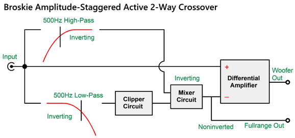
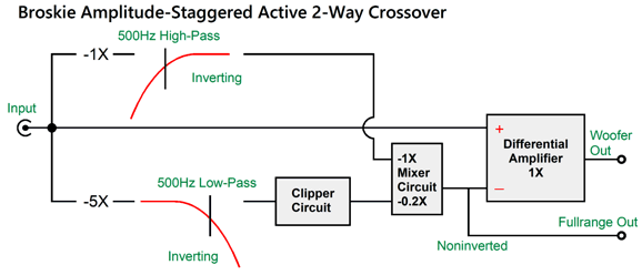
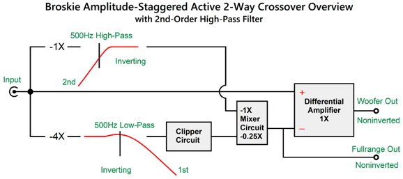
We have added a 1st-order two-way 500hz crossover and a mixer circuit. The clipper circuit consists of the two signal diodes and a series resistor; the mixer circuit, an inverting amplifier with two inputs. If the clipper circuit is never triggered, the low-pass filter and high-pass filter outputs combine to unity, hence no phase shift or frequency alteration. The differential amplifier seeing exact same signal at its non-inverting and its inverting inputs, delivers nothing at its output, as it only passes a difference, of which there is none. Once the input signal amplitude increases to the point where the clipper circuit is engaged, a difference develops, which the differential amplifier passes on to the woofer power amplifier. The fullrange driver gets the entire signal above 500Hz and that portion of the frequencies below 500Hz remaining that come out of the clipper circuit.
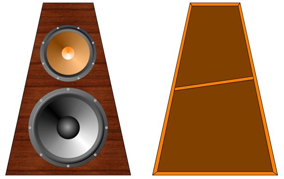
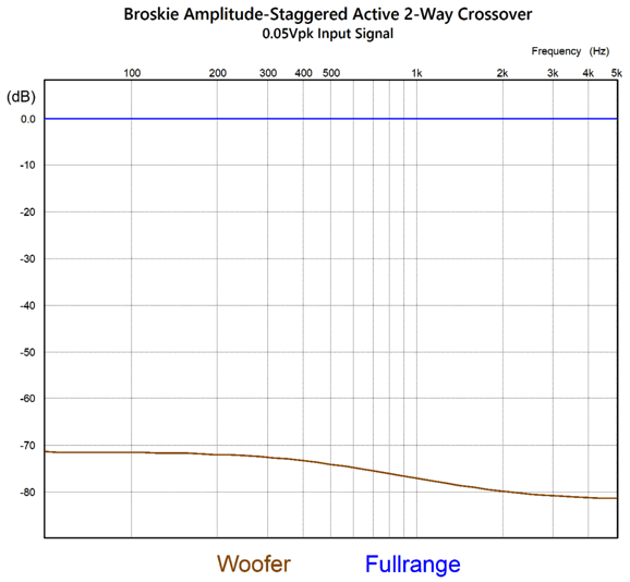
This is the loudspeaker I would love to build: a 5in fullrange driver and a 6in or 7in woofer. Each driver gets its own sealed volume of air, possibly with a sloping front panel, so as to prevent front-to-back parallel walls. Of course, this arrangement can be scaled either up or down. Imagine a small computer loudspeaker that held a 3in fullrange driver and a 5in woofer—or, a tall, narrow speaker cabinet that held one 5in fullrange driver at the top and four 5in woofer below it. (A co-axial driver could substitute for the fullrange driver, by the way.) I ran my circuit design in SPICE simulations and got the following graph for low-amplitude input signals.
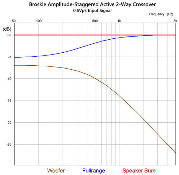
To be -60dB down means that the woofer would only 1/1,000 of the signal amplitude that the fullrange driver sees; and -80dB, 1/10,000 as much. Effectively, just the fullrange driver is producing any sound. As the input signal increases, the voltage division alters. Here is the graph for 0.5Vpk of input signal.
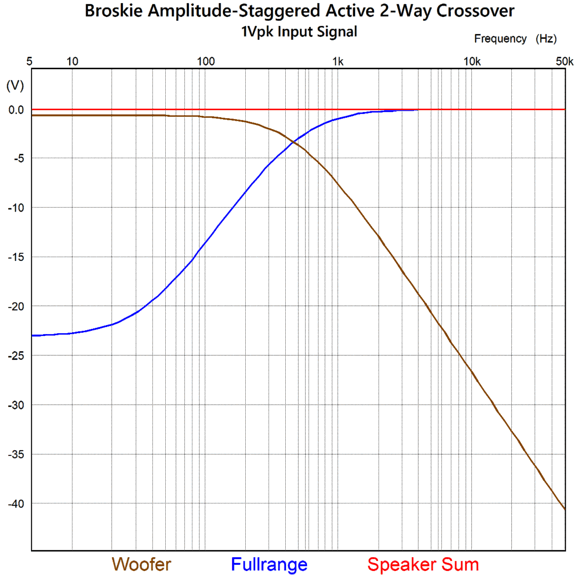
The two drivers sum to unity and the crossover slopes become evident; with 1Vpk of input signal, the crossover is obvious.
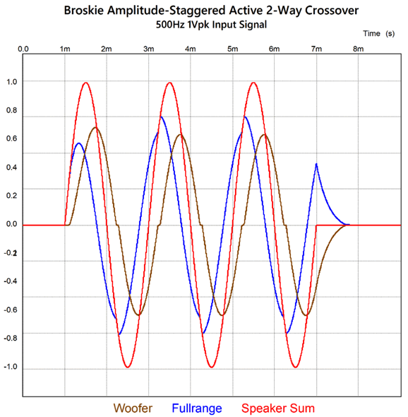
Here is a transient graph of a three-cycle tone burst at 500Hz, the crossover frequency.
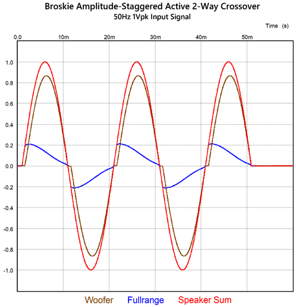
The two drivers deliver roughly the same amount of output, and they sum to unity. In other words, we get three clean cycles at 500Hz. If we move the test tone frequency down to 50Hz, we get this result.
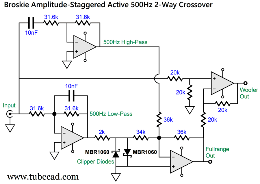
Do not forget that wattage equals voltage² divided by resistance, so that 20% of the input signal does not mean 20% of the power dissipation, but 0.20² as much, i.e. 4%. In other words, the woofer is doing 96% of the work here. So far, I have been explicating function, not the how to realize the function. Here was my first attempt at a Broskie Amplitude-Staggered Active Crossover (BASAC).
Four OpAmps are required, all of which must be unity-gain stable. The clipping diodes are MBR1060 types, which are 10A, 60V Schottky-barrier rectifiers packaged in a TO-220AC case. They are also obsolete, as better rectifiers now exist. So why did I use them? They exhibit a tiny turn-on voltage at light current flow; besides, I have a SPICE model for them. Since their turn-on voltage is so low, I didn't have to pre-amplify the input signal, which allowed me to use the same resistor value on all four crossover filter resistors. Both of the crossover OpAmps (those on the left) are configured as inverting amplifiers. The bottommost OpAmp is set up as a mixer, which also inverts, so its output will be in phase with the input signal. In fact, if the input signal is small enough in magnitude to fail at engaging the diodes, the mixer's output will be identical to the input signal, as the two filter outputs sum to unity.
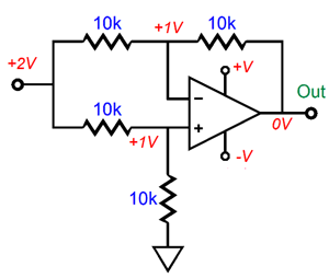
The rightmost OpAmp is configured as the differential amplifier. Its job is to compare the mixer's output to the input signal. If there's any difference, the differential amplifier will pass it on to the woofer's power amplifier. I had two issues with this design: the clipping diodes (MBR1060) exhibit a relatively high capacitance (400pF) and the need for two tight-tolerance capacitors in the crossover filter section. In contrast, the near-universal signal diode, the 1N4148, comes in at 2pF of capacitance, but with a higher turn-on voltage. Applying some signal gain can overcome this last limitation. As for eliminating one capacitor, the workaround is to use a mixer circuit that effectively acts like as differential amplifier.
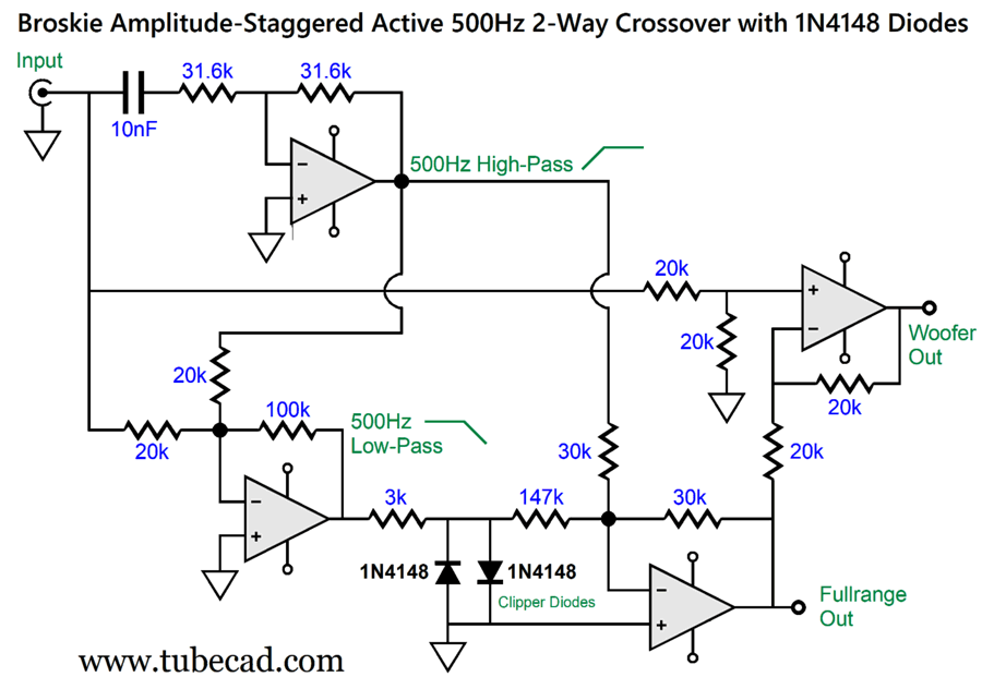
Okay, I know that a few readers are scratching their heads right now. Let's start at the top: the topmost OpAmp functions as, just like before, as an inverting 1st-order high-pass filter. The OpAmp below it has its non-inverting input grounded, so no signal should appear at its inverting input, as the whole point behind the OpAmp is that it strives to maintain identical signals between its two inputs. The high-pass filter output is inverted, so automatically nulls any high-frequencies above the crossover frequency when it meets the input signal through the two 20k resistors. The input signal that remains must be nulled by an inverted signal from the OpAmp's output, which equals an inverted low-pass filter at 500Hz. In addition, the OpAmp's output must be five times greater in amplitude due to the 100k negative feedback resistor. (Think in terms of current, and this will make perfect sense, as 1/20k = 5/100k.) The five-times-bigger signal must pass past the clipper diodes. If it passes intact, it will be reduced by fivefold and combine with the high-pass filter output to sum to unity, leaving no signal for the woofer and all the signal for the fullrange driver amplifier.
If the clipper diodes engage, however, the fullrange driver gets less bass signal, while the woofer sees more. In other words, this version is functionally isomorphic (identical) with the previous one, but uses one less capacitor and different diodes. Here is the overview of the circuit.
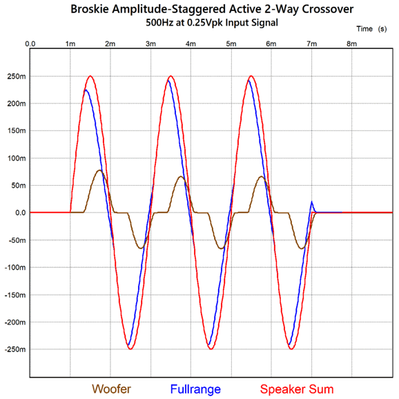
In SPICE simulations, this circuit worked just as well as the previous circuit. With an input signal of 0.25Vpk, we see the following voltage relationships.
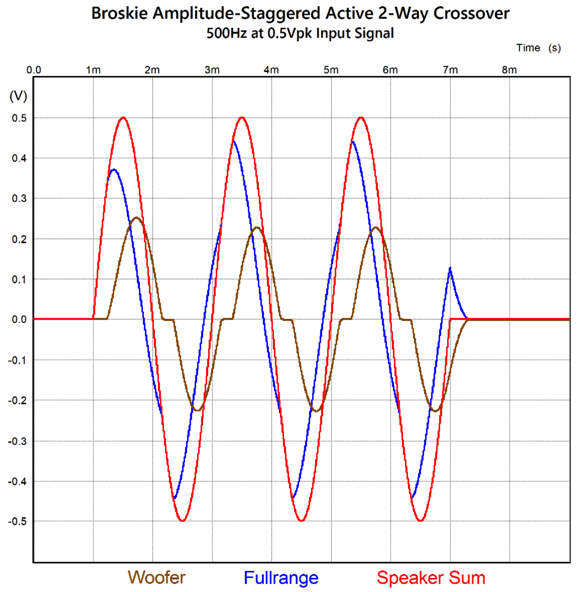
The woofer's output adds only a little to the summed output. Doubling the input signal to 0.5Vpk, yields more woofer output.
With 1Vpk of input signal, we get the same results as the first version delivered. Are we done? No. The problem with a 1st-order crossover is that the high-frequency driver's cutoff slope is so shallow that it offers limited protection to the delicate driver. Can we use a sharper filter type in the low-pass and high-pass filters, such as the Linkwitz-Riley 2nd-order or Butterworth 3rd-order? Sadly, no, as these crossover types do sum to flat in terms of frequency response, but not in terms of phase. What we need is a phase-flat asymmetrical two-way crossover. Here is the needed overview:
Note that I only specified an amplification of 4X (+12dB) of the input signal, not the 5X of the previous design, as I wanted to give the fullrange driver a lower trigger voltage for the clipping circuit. Also note that the mixer inverts both input signals and divides the clipper circuit's output by four. Here is one possible asymmetrical/flat-phase two way crossover.
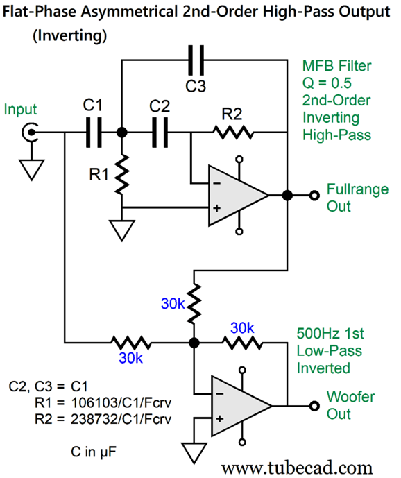
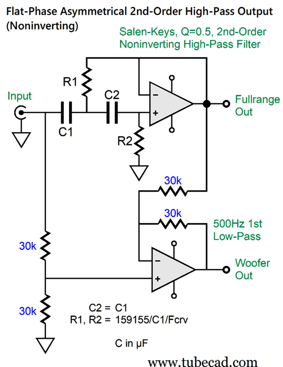
The multiple feedback (MFB) 2nd-order high-pass filter inverts the input signal at its output. The mixer circuit, functioning as a differential amplifier, delivers the perfect complement to create a summed unity, both in frequency response and flat phase. The Salen-Keys equivalent looks like the following:
Note how the differential amplifier is differently configured now, as the Salen-Keys high-pass filter is non-inverting. Okay, let's put it together.
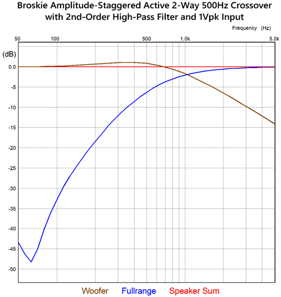
With a 1Vpk input signal, we get the following frequency division.
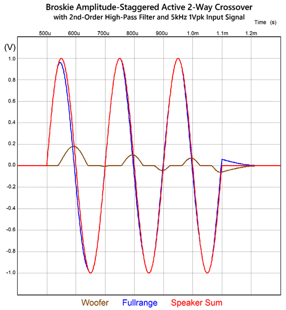
The fullrange driver's low-frequency cutoff is now 2nd-order, while the woofer's is a lumpy 1st-order. If we apply an input signal of a three-cycle 5kHz tone burst, we get the following:
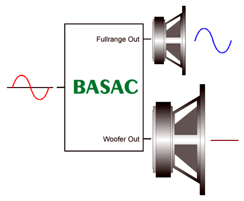
Note how the woofer's output decrease with each cycle. A quick recap is needed. Here is the signal division between drivers when the input signal is small.
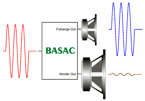
With the large input signals at high-frequencies, we get something like this.
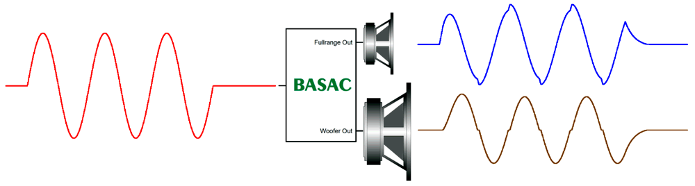
But with large input signals at the crossover frequency, we get the following.
Are we done? Yes, for this post that is; for example, I could try to create a tube-based version of these circuits for a future post. In addition, I can imagine inserting the BASAC into a bi-amped loudspeaker system which would transition to three-way tri-amped system at high SPLs. Or, how about a subwoofer version? In other words, while this post is done, I am never done.
If I were so shameless as to evaluate and judge this effort of mine, I would give the BASAC one and a half Musk Prizes.
Music Recommendation: TakéDaké with Neptune's Asian Roots Once again, the recording is only in 16-bit, 44.1kHz format, yet delivers an unbelievably great stereo image and tonality. I also agree with Daryl Wilson's pick of the track, "Japanese Roots," as the standout audio demo track. If you are going to hold any sonic shootouts between amplifiers, cables, DACs, or loudspeakers, this is the track to use. Wilson uses it to evaluate tonal purity and sound decay. If the different instruments sound the same or end abruptly, failing to softly fade away, the system needs an upgrade. Neptune is John Kaizan Neptune, born in Oakland, California in 1951. He an accomplished musician who loves bamboo musical instruments; thus, the name of the album, TakéDaké, which means "Bamboo Only" in Japanese. Yes, all the instruments are made of bamboo. Here is a link to valuable information on the Asian Roots album. Be sure to listen to the entire album, as it is filled with both artistic and sonic gold. //JRB
Adobe AI Summary: This document discusses advanced audio amplifier and loudspeaker design concepts, including push-pull amplifiers, amplitude-staggered subwoofers, and innovative full-range driver configurations. Historical Perspective on Push-Pull Amplifiers
Modern Active Crossover Concepts
Amplitude-Staggered Circuit Functionality
Advanced Active Crossover Designs
Practical Implementation and Simulation Results
Music Recommendation
Did you enjoy my post? Do you want to see me make it to post 1,000? If so, think about supporting me at Patreon.
|
I know that some readers wish to avoid Patreon, so here is a PayPal button instead. Thanks. John Broskie
John Gives
Special Thanks to the Special 89 To all my patrons, all 89 of them, thank you all again. I want to especially thank
I am truly stunned and appreciative of their support. In addition I want to thank the following patrons:
All of your support makes a big difference. I would love to arrive at the point where creating my posts was my top priority of the day, not something that I have to steal time from other obligations to do. The more support I get, the higher up these posts move up in deserving attention.
If you have been reading my posts, you know that my lifetime goal is reaching post number one thousand. I have 353 more to go. My second goal was to gather 1,000 patrons. Well, that no longer seems possible to me, so I will shoot for a mighty 100 instead. Thus, I have just 11 patrons to go. Help me get there. Thanks.
New URL of the GlassWare website |
||||






| www.tubecad.com Copyright © 1999-2026 GlassWare All Rights Reserved |