| John Broskie's Guide to Tube Circuit Analysis & Design |
November 20 2024 Post Number 611
Solid-State Janus Shunt Regulator
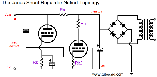
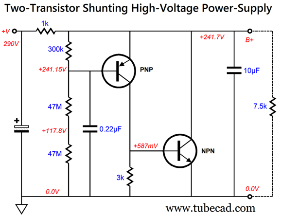
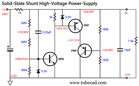
Most regulators, both high-voltage and low-voltage, both series and shunt, only react to noise in the forward direction, i.e. their output voltage. They react to and work to eliminate any deviation from the desired noise-free output voltage, whether the perturbations result either from the raw-rectifier ripple or from load-current variations induced by the audio circuit being powered. In contrast, the Janus also reacts to the signal-induced fluctuations but proactively anticipates and counters the raw rectifier noise. Although the original Janus regulator was an all-tube design, I have also shown several hybrid variations, such as in post 237, post 548, and post 588. Well, creating an all solid-state Janus is possible. In fact, it is easier to design due to solid-state devices coming in both N-versions and P-versions, such as NPN and PNP transistors, something that is impossible with tubes, which come only in an N-version. My design goal was a -100dB reduction in ripple at the output, which equals 1/100k as much ripple. This is an ambitious goal, as a -100dB PSRR usually requires elaborate discrete circuitry or OpAmps, which stands in opposition to my secondary goal: super simple, with the fewest parts possible. The following is an example of a non-Janus but shunting high-voltage solid-state regulator that uses only two high-voltage transistors.
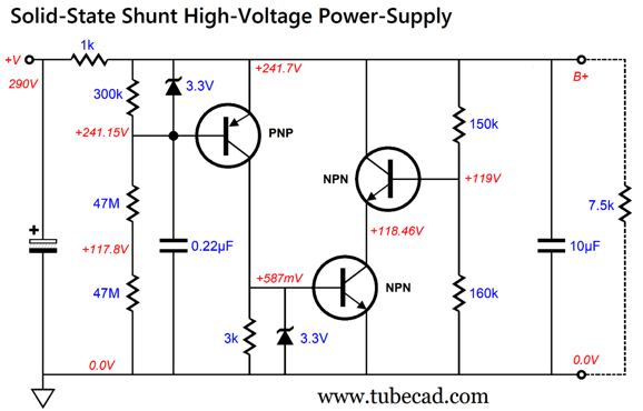
The PNP transistor controls the NPN transistor's current conduction, varying its current flow to create the smallest possible difference in the AC signals present on the PNP transistor's emitter and base. In other words, negative feedback. The 0.22µF capacitor effectively grounds the PNP transistor's base to AC voltages, while the PNP transistor's emitter directly connects to the shunt regulator's output. If the B+ voltage bounces up in voltage, the PNP transistor increases its conduction, thereby in turn increasing the voltage at the NPN transistor's base, forcing the NPN transistor to greater current conduction, which will counter the positive bounce in voltage by increasing the voltage drop across the series 1k resistor, undoing the bounce. If the B+ voltage momentarily sags, the PNP transistor forces the NPN transistor to ease up on its conduction, which will prompt a smaller voltage drop across the series 1k resistor, filling in the sag. The PNP transistor draws very little current, thus its heat dissipation is low. In contrast, the NPN transistor draws far more current, so its dissipation is necessarily greater. We can, however, place two NPN transistors in cascode, thereby halving the dissipation per NPN transistor.
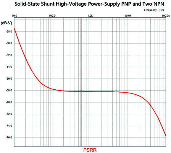
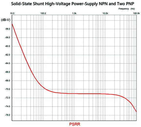
The 150k and 160k resistors form a two-resistor voltage divider that splits the voltage across the two NPN transistors. The added 3.3V zener diodes are there to protect the transistors. In SPICE simulations the PSRR was fairly good—but not -100dB good, alas.
An additional problem is that high-voltage PNP transistors are rarer than high-voltage NPN transistors. The workaround is to invert the shunt regulator.
Note how the 150k and 160k resistors have traded places. Also note that the 47M resistors have been replaced by 24M resistors. Why? The MJE340 NPN transistor that I used in my SPICE simulations offers a lower beta compared to the MJE350 PNP transistor. The SPICE PSRR test revealed a slightly improved PSRR.
I am happy to see the improvement, but we are still far from the goal of -100dB at 100Hz. In short, a single-transistor amplifier does not offer that much gain. Okay, let's see if adding some Janus backward sensing doesn't improve the performance.
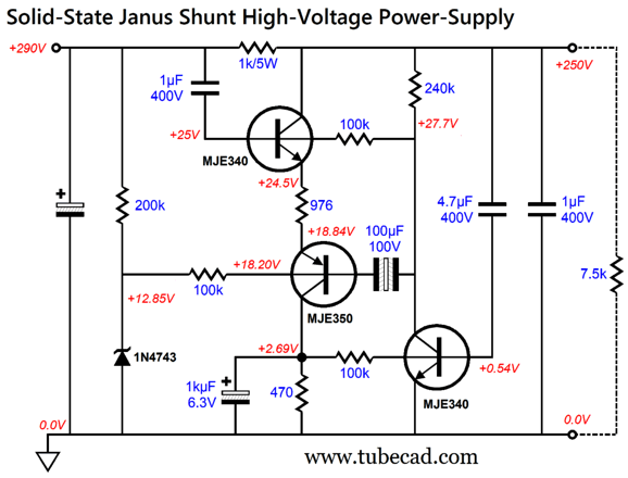
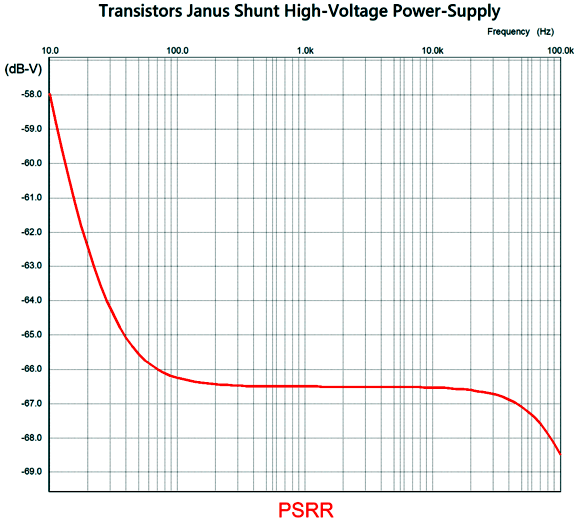
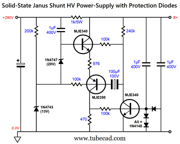
Admittedly, there's a lot going on here, as the circuit incorporates auto-biasing along with AC noise reduction. The 470-ohm collector resistor is the current-sense resistor in this circuit that sets a 5.7mA current flow through the MJE340 and MJE350 transistors in series with the emitter 976-ohm resistor. The bottommost MJE340 transistor monitors the voltage drop across the 470-ohm current-sense resistor. If the resistor sees too great a voltage drop, the NPN transistor's current conduction increases, which in turn creates a greater voltage drop across the 240k collector resistor, thereby reducing the voltage drop and current conduction through the 976-ohm and 470-ohm resistors. The 1 µF capacitor that attaches to the raw power-supply voltage relays all of the ripple to the topmost MJE340 transistor's base, which then superimposes the ripple upon the 976-ohm resistor, thereby creating an antiphase voltage drop across the series 1k resistor, which nulls the ripple at the output. Whatever AC noise that appears on the output side of the 1k series resistor is relayed through the 4.7 µF capacitor to the bottommost MJE340 transistor's base, whereupon the this transistor amplifies the AC noise in antiphase, which in turn drives the MJE350 PNP transistor's base. The MJE350 is configured as an emitter follower, so the antiphase noise signal creates an antiphase current conduction through the MJE340-MJE350 string, reducing the AC noise at the output. How well does this solid-state Janus perform?
Not bad, but still not -100dB good. In addition, I worry about taking out the some of the transistors at turn-on and turn-off. The workaround is to add some protecting diodes (and a zener diode).
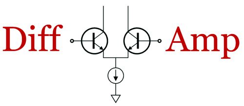
Once again, a single-transistor negative feedback amplifier does not offer that much gain. Well, by using two amplifying transistor side-by-side, we can double the amount of gain.
Differential Negative-Feedback Janus
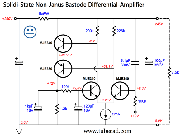
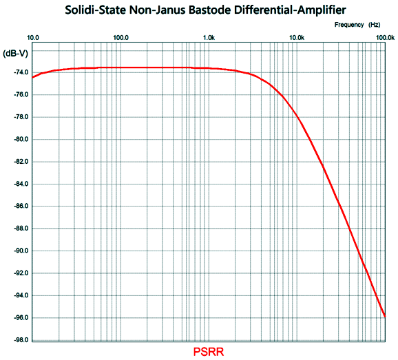
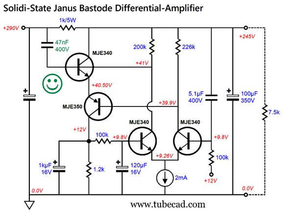
The MJE340-based differential amplifier drives the bastode arrangement of the MJE340 and MJE350 in series. Since we assume that this high-voltage shunt regulator will be used to power tube gear, we can assume a regulated 12Vdc power supply for the heaters, which grants us a free 12V voltage reference—as long as the heater power supply is grounded. Since this shunt regulator is a regulator only in terms of AC power-supply noise, not DC output voltage, this 12V voltage reference is used not to establish a fixed output DC voltage, but rather to auto-bias the bastode transistors to a predetermined idle current flow. The 1.2k collector resistor is the current-sense resistor and it is bypassed by the 1kµF capacitor and RC filtered by the 100k resistor and 120µF capacitor. (In other words, we need to strip away the AC from the DC signal.) The way the regulator looks forward is simple enough: any AC perturbation in the B+ voltage gets relayed to the rightmost MJE340 transistor's base, which will force antiphase output voltage swings from the differential amplifier's outputs, which in turn prompts huge swings in current conduction from the bastode transistors, resulting in a huge reduction in that perturbation. Well, at least that's the theory. Here is what SPICE shows:
Better, but still not -100dB at 100Hz. Next, we inject some Janus mojo.
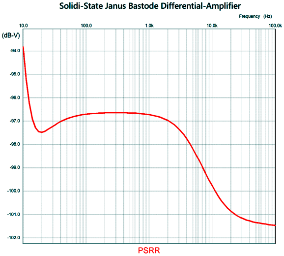
The added 47nF (i.e. 0.047µF) capacitor leaks enough of the raw rectifier noise into the circuit to improve the PSRR substantially.
Wow! and dang! at the same time. First, that's an impressive improvement; second, a pity that it still falls short of -100dB.
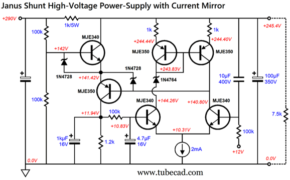
By the way, now is a good time to say thanks to John Atwood. Thanks, John. You long ago showed me how sometimes we can add noise to circuit to eliminate noise at the output. I was scratching my head, wondering how to produce more gain from the differential amplifier stage, when the idea of replacing the differential amplifier's collector resistors with a current mirror immediately came to mind.
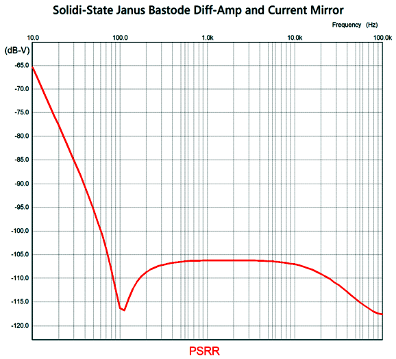
The current mirror effectively loads the differential amplifier with a constant-current-source like high impedance on its right collector, increasing gain considerably. In addition, it creates a push-pull output from the differential amplifier that can produce peak output current swings roughly equal to the constant-current source current. The two 1N4728 zeners are 3.3V types, which protect the bastode transistors, while the single 1N4764 is a 100V zener, which equalizes the collector voltages on the difference amplifier's two MJE340 transistors. The Janus aspect of looking both backwards and forwards is still there, as the two 100k resistors in series on the left function as a two-resistor voltage divider for both AC and DC voltages. (The topmost MJE340 draws base current from the top 100k resistor, thus the failure to split the 290Vdc down to exactly 145Vdc.) In other words, 50% of the raw rectifier ripple is presented to the topmost MJE340 transistor's base. Well, did we reach our goal?
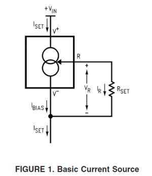
Merciful heaven, we have arrived—with an added -15dB to spare at 100Hz. Speaking of 100Hz, I tuned this shunt regulator to dip most 120Hz, by selecting the low-voltage capacitor values and the 10µF high-voltage capacitor value. Change these values and the dip moves to another frequency or, possibly, disappears altogether. The constant-current source can be made from an LM334 with a current-setting resistor value of 34 ohms.
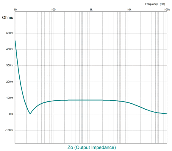
Another way to evaluate a voltage regulator is to look at its output impedance versus frequency graph.
From 10Hz to 100Hz, the output impedance is below 0.1 Ohms. Are we done? Of course, not. We are never done. One thought that comes to mind is what if we stuck to only four transistors, but kept the constant-current source?
Doubled Bastode Regulator
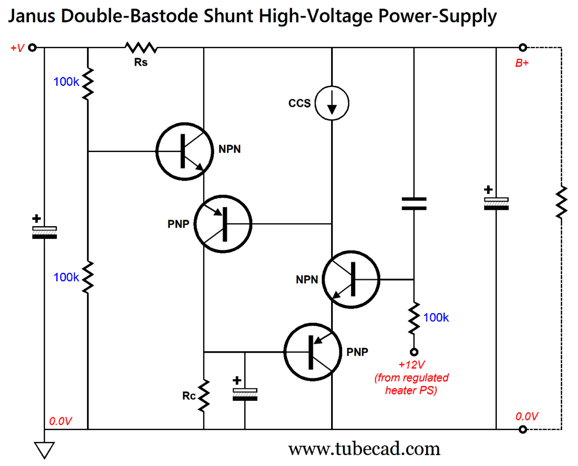
We have already used the bastode arrangement in the previous shunt regulator designs, so why not double up on it?
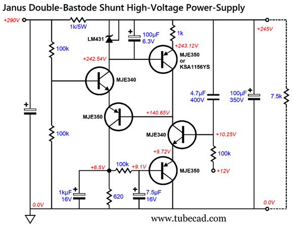
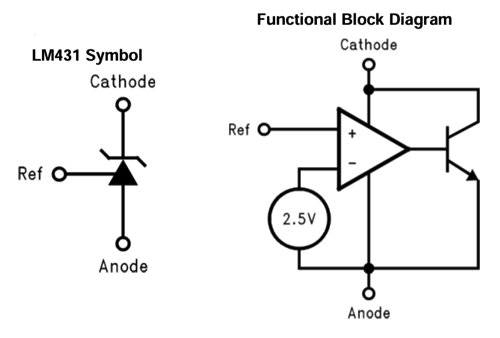
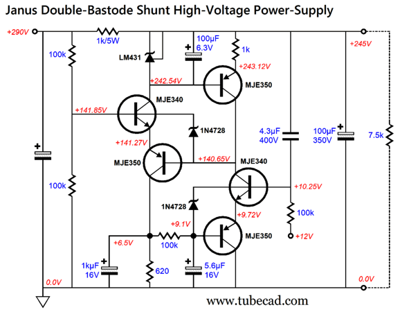
This is the overview of the topology. The two 100k resistors at the left form a two-resistor voltage divider that both injects 50% of the power-supply noise and delivers roughly half the raw DC voltage to the topmost NPN transistor's base. Resistor Rc is the current-sense resistor, which is shunted by a large-valued capacitor to shunt away the AC signal and effectively AC grounds the bottommost PNP transistor's base. The bastode on the right forms the high-gain error amplifier that drives the bastode on the left. We borrow the heater's regulated 12Vdc power-supply voltage as bias voltage for the bastode's input. The constant-current source isolates the power-supply noise and promotes high gain. The constant-current source could be made from a high-voltage constant-current source device such as the IXYS 10M45S or the Supertex DN2540. Alternatively, we could make a constant-current source with a PNP transistor and a voltage reference. The LM431 is a shunting adjustable voltage reference; with its Reference pin tied to its cathode, it defaults to a 2.5V voltage reference.
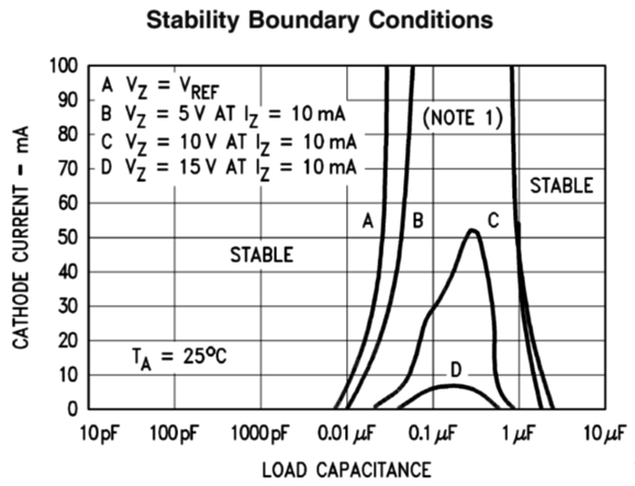
The LM431 is shunted with a 100 µF capacitor. The device's data sheet revealed that this value of capacitance was safe.
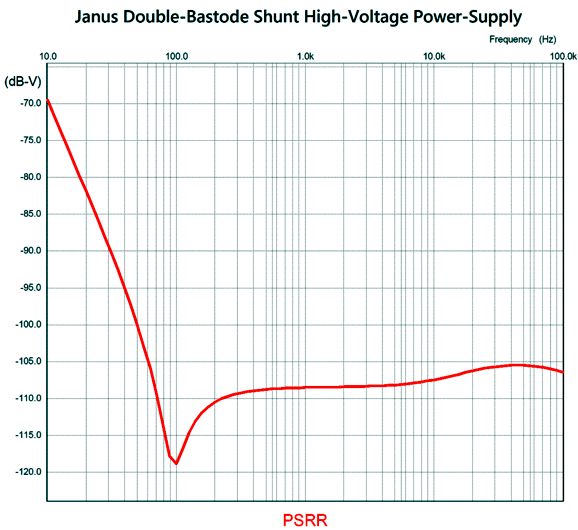
From the graph, we see that any value above 10 µF is stable. The 1k emitter resistor sets the constant-current source idle current to 1.92mA. SPICE simulation revealed an excellent PSRR.
This time, the deepest dip occurs at 100Hz, for those living in 50Hz AC wall-voltage frequency countries. To target 120Hz, we replace the 4.7 µF capacitor with a 4.3 µF capacitor; the 7.5 µF capacitor, a 5.6uf capacitor. Note the added two 3.3V zeners. They are there to protect the transistors at turn-on and turn-off. By the way, the bastode on the left, the one that idles at higher current and dissipates the most heat, can be swapped out for beefier transistors in the TO-220 package, such as the MJE15034 and MJE15035, which are complementary 50W, 350V power transistors. I quite like this circuit, but I should explain why it might prove better in actual use than the alternate version that replaced the bastode differential amplifier in the right with a single OpAmp. The OpAmp, with its insanely high open-loop gain, would certainly offer greater PSRR—but it would also likely create headaches, such as oscillation and instability issues like latch-up at startup. The problem is that we cannot dig into the OpAmp and make changes to its circuitry. With the discrete parts openly available in the bastode amplifier, we can easily make changes to part values or add an extra capacitor.
Revisiting the Broskie OTL
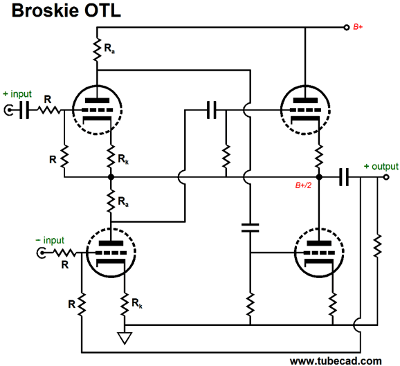
The BCF was born about 30 years ago when a French recording engineer asked if I could design a tube-based circuit to replace the 1:1 signal transformers that he used to convert balanced signals into an unbalanced signal. The BCF was that design. Once the topology was revealed to the audio world, I got an email stating that the circuit was being used to drive 300-ohm headphones. I was sure that it wasn't up to the task, so I performed a test using my own Sennheiser 300-ohm headphones. Amazingly, it worked really well. I still worried about someone trying to drive low-impedance headphones, so I devised my Broskie OTL topology. Once again, like the BCF, a set of balanced input signals are converted into an unbalanced output signal, but this time supercharged.
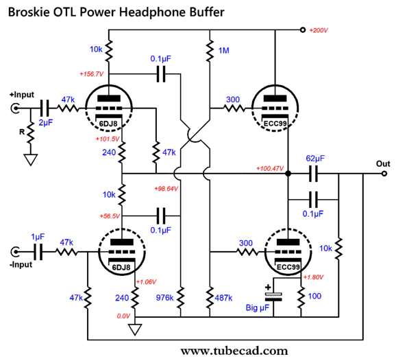
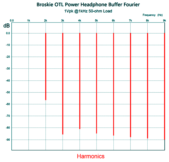
The high-mu triodes on the left both drive and control low-mu, high-current triodes on the right, which can be fixed-biased rather than cathode-biased. Think 6DJ8 on the left, a 6AS7 or 6H30 or ECC99 on the right. To see how this push-pull buffer works, imagine forcing a 1V positive pulse on the output, while both inputs are grounded. The bottom input triode sees the 1V pulse halved to +0.5V, which it amplifies and inverts at its plate, which in turn feeds the top output triode a big negative pulse at its grid. At the same time, the top input triode also sees the 1V pulsed halved, but its cathode sees the full 1V pulse, so effectively its grid sees a -0.5V pulse, which forces its plate voltage to swing up, delivering a huge positive pulse to the bottom output triode's grid. In other words, the positive pulse is countered powerfully and equally by both output triodes, resulting in both low distortion and output impedance. Here is a design example using the 6DJ8 and ECC99 pairing. By reading the voltage drop across the 100-ohm cathode resistor, we see that the output stage draws 18mA of idle current, thereby creating about 1.8W of dissipation from each ECC99 triode. Since the output stage is push-pull, the class-A window of output current flow is twice the idle current, or 36mA peak. This is enough to deliver around 2Vpk into 60-ohm headphones. In addition, since this is a push-pull output stage, it can be run in class-AB. In other words, lots more output power is possible than in a single-ended buffer. I ran this design in SPICE simulation and was astounded by the resulting Fourier graph for 1Vpk at 1kHz into 50 ohms. The THD was 0.2%, and the low-frequency cutoff frequency was 27Hz. Both are amazing, as a 50-ohm load is brutally low for a noval tube-based output stage, and a 60µF capacitor output coupling capacitor should impose a 57Hz low-frequency -3dB-down frequency. The answer is found in the Broskie OTL's high internal negative feedback, which increases linearity and extends bandwidth, along with lowering output impedance. Returning to the Fourier graph of harmonics, I marveled at the single-ended flavor and the wonderful further suppression of the 3rd harmonic, which produces the dreaded canned sound.
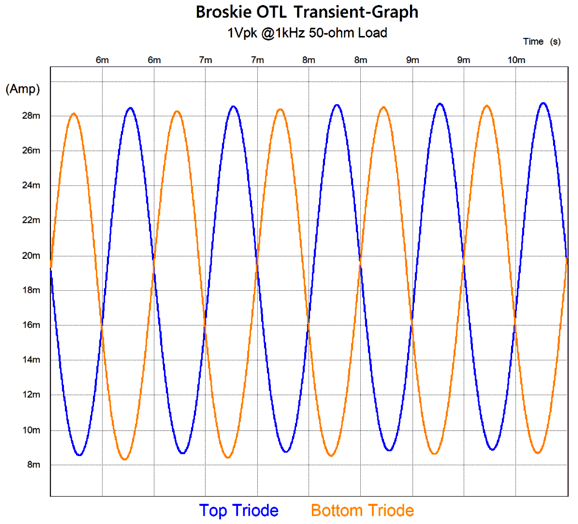
The strong 2nd harmonic and weak 3rd should bestow a lovely tube sound, warm and dynamic. The next graph shows the excellent current-swing balanced between the two ECC99 triodes.
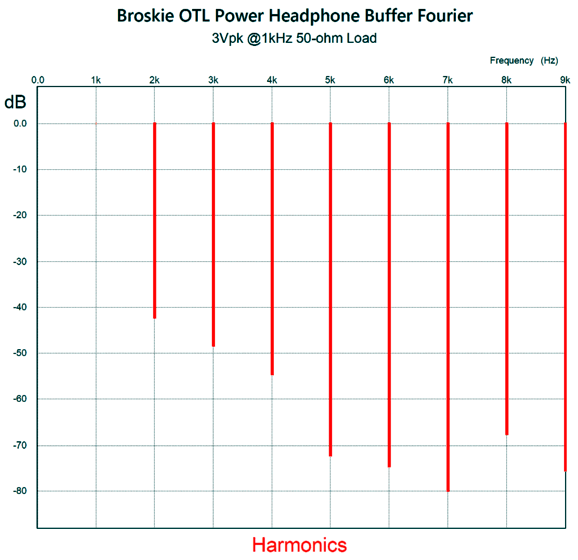
The next test is with the same load impedance and test frequency, but with 3Vpk.
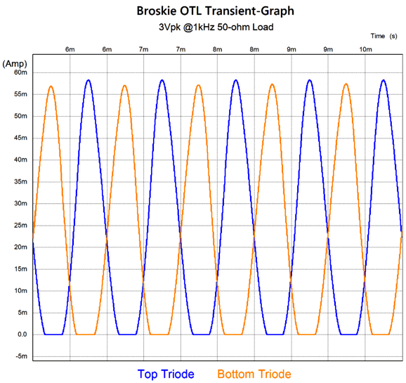
We have left the class-A window of output, but the harmonic structure still looks very single-ended. The THD translates into 0.7%. The output triode current swings reveal the push-pull class-AB operation.
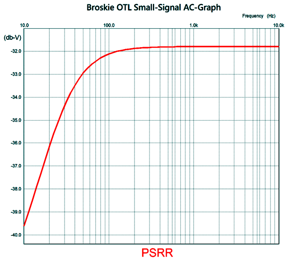
I worried about this tiny OTL's PSRR, but it turned out to be far better than I expected.
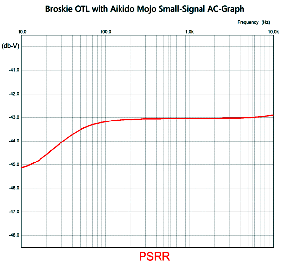
Not bad. If we use a regulated high-voltage power supply, then we are set. I wondered if an injection of Aikido mojo wouldn't improve the situation. Indeed, it did.
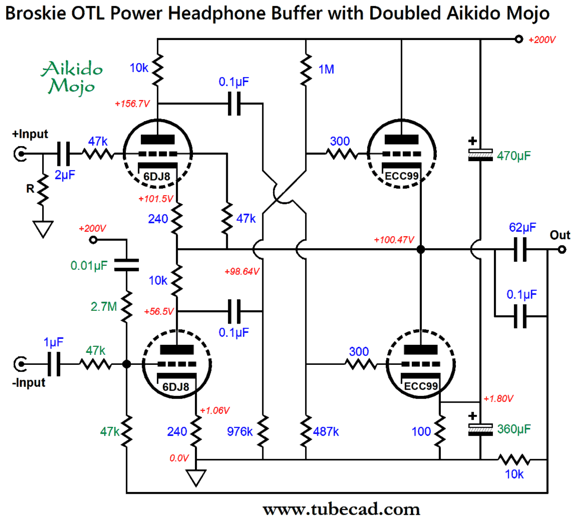
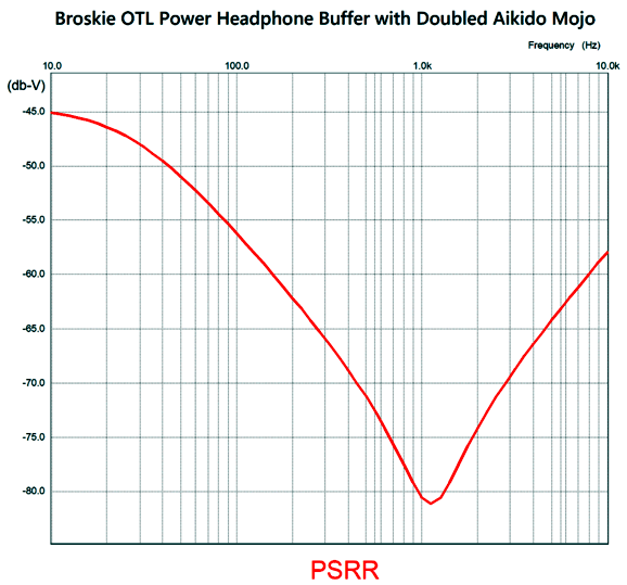
The added 470 µF capacitor along with the 360 µF capacitor cathode bypass capacitor inject just enough power-supply noise to reduce the PSRR. An 11dB improvement roughly translates to quartering of the power-supply noise leaking out at the output. Still, I expected more. The problem is found in my having only applied Aikido mojo to the last half the circuit. Now the bottom input triode gets a small injection of power-supply noise, resulting in better PSRR.
Wow! Assuming a wall-voltage frequency of 50Hz, we see rectification harmonics at 100Hz, 200Hz, 400Hz, 800Hz… Well, the downward slope from 10Hz to 1200Hz will extinguish those harmonics nicely. When driving 300-ohm loads, this unbalancing power buffer delivered excellent performance, which we would expect, as its output tubes never exceeded the window of class-A operation. I wondered how the circuit would perform with a much larger output coupling capacitor. A mixed bag. Indeed, the THD dropped, as negative feedback wasn't being expended to extend low-frequency bandwidth, but the harmonic structure took on a strong push-pull flavor, sadly.
Music Recommendation: More Icelandic Classical Music I have recommended Icelandic classical music before: in Post 511 I recommended Concurrence, an album by the Iceland Symphony Orchestra, conducted by Daníel Bjarnason; in Post 527, Anna Thorvaldsdottir's album, Aerial. Not only does Iceland seemingly hold scores of female classical composers, it also contains at least one babe composer, Bara Gsladttir.
As long as she doesn't appear scantily clad on an album cover, I am all for it. Pulchritude is always welcome, especially given its opposite's overwhelming plenitude. Nonetheless, classical music should remain classy. From Post 518:
(It is amazingly fun to quote oneself.) If you are expecting Taylor-Swift grade classical music, bouncy, teenage-glee-and-angst filled classical music from Ms. Gsladttir, you will be disappointed. She, like so many Nordic composers, writes dang somber music, which no suicide-prevention hotline would dare use for their on-hold music. I love it. Nothing cheers me up like hearing some somber music. I remember my thrill at first hearing Rachmaninoff's "Isle of the Dead" symphonic poem, which starts dark and funereal and ends bereft of hope. I remember extolling it to my friend, Bill, who explained to me: "John, you seem to have forgotten that you are a fundamentally happy person who likes depressing music, whereas I am a constantly depressed person who likes happy music." Here are some of her albums that I enjoyed hearing.
Bára Gísladóttir, Orchestral Works
The next two albums are interesting in that they only hold one track, one very long track.
Bára Gísladóttir, SILVA
Bára Gísladóttir, VÍDDIR (Live)
//JRB
Did you enjoy my post? Do you want to see me make it to post 1,000? If so, think about supporting me at Patreon.
User Guides for GlassWare Software
For those of you who still have old computers running Windows XP (32-bit) or any other Windows 32-bit OS, I have setup the download availability of my old old standards: Tube CAD, SE Amp CAD, and Audio Gadgets. The downloads are at the GlassWare-Yahoo store and the price is only $9.95 for each program. So many have asked that I had to do it. WARNING: THESE THREE PROGRAMS WILL NOT RUN UNDER VISTA 64-Bit or WINDOWS 7, 8, and 10 if the OS is not 32-bit or if it is a 64-bit OS. I do plan on remaking all of these programs into 64-bit versions, but it will be a huge ordeal, as programming requires vast chunks of noise-free time, something very rare with children running about. Ideally, I would love to come out with versions that run on iPads and Android-OS tablets.
|
I know that some readers wish to avoid Patreon, so here is a PayPal button instead. Thanks.
John Broskie
John Gives
Special Thanks to the Special 88 To all my patrons, all 88 of them, thank you all again. I want to especially thank
I am truly stunned and appreciative of their support. In addition I want to thank the following patrons:
All of your support makes a big difference. I would love to arrive at the point where creating my posts was my top priority of the day, not something that I have to steal time from other obligations to do. The more support I get, the higher up these posts move up in deserving attention. If you have been reading my posts, you know that my lifetime goal is reaching post number one thousand. I have 393 more to go. My second goal was to gather 1,000 patrons. Well, that no longer seems possible to me, so I will shoot for a mighty 100 instead. Thus, I have just 8 patrons to go. Help me get there. Thanks.
New URL of the GlassWare website |
|||
| www.tubecad.com Copyright © 1999-2024 GlassWare All Rights Reserved |




 Circuit.png)





%20Cover.jpg)


