| John Broskie's Guide to Tube Circuit Analysis & Design |
25 August 2020 Post Number 511
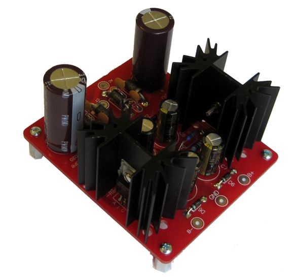
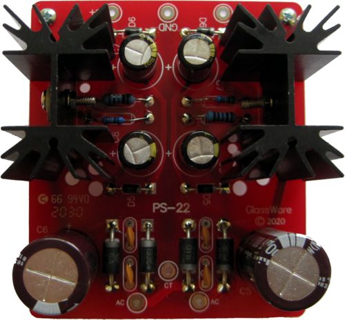
New Bipolar Power Supply: PS-22 Either a 1.5 inch or 2.5 inch tall heatsinks are the options. The 1.5 inch tall heatsink presents a thermal resistance of 3.7C/W, while its 2.5 inch brother offers a low 2.6C/W resistance. How do these two thermal resistances translate into actual performance? If the 3.7C/W heatsink were attached to a TO-220-encased resistor that dissipated 10W of heat, the heatsink would increase in temperature by 37C, as in 37 degrees celsius (centigrade). Now 37C is not that hot, as it is your core body temperature. But the 37C must be added to what ever temperature the heatsink was at prior to the resistor's heat generation. Usually, we assume 25C, 77 degrees in Fahrenheit, as the average room temperature. Inside a tube-filled chassis, this assumption might fall short of reality by 15C or more. On a hot summer's day, inside your tube power amplifier chassis, the ambient temperature might be closer to 50C (122 degrees in Fahrenheit). Ouch! As 50C added to 37C yields 87C, which produces a burning hot heatsink and, most probably, a toasted voltage regulator. My own self-imposed limit to heatsink temperature is 60C, as that is about as hot as I can bear to touch without gloves. So, if we work backwards, and if we assume 35C to be the internal enclosure temperature, and if we want to limit the 3.7C/W heatsink to no more than 60C, then the heat generating device, be it a voltage regulator or transistor or MOSFET or power resistor, cannot produce more than (60C - 35C) / 3.7C/W or 6.75W. If we use the taller heatsink, however, with is lower 2.6C/W thermal resistance, we can allow dissipation up to 9.6W. Of course, if the tall heatsink does not fit in the enclosure, its lower thermal resistance will not do us any good. Most OpAmp-based circuits draw relatively little current, say a total of 50mA, which against a voltage regulator's voltage drop of 4Vdc equals only 0.2W of heat. But if the OpAmp circuit is a headphone amplifier or a complex OpAmp-based circuit, then the larger heatsinks become a much bigger asset.
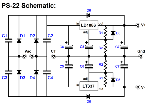
The PS-22's schematic is simple and straightforward. A full-wave bridge rectifier circuit converts the secondary's center-tapped AC voltage to bipolar DC voltages. Thereafter, the positive and negative adjustable regulators put out the desired rail voltages. The actual star of this show is the rectifier, a MUR410G, which is an exemplary 4A/100V rectifier. From its data-sheet:
A comparable rectifier is the 1N5401, which is a 3A/100V device with a recovery time so slow that none of the four data-sheets I could find specified its value, other than to state that it was a standard-recovery rectifier, which implies a recovery time of >500ns. The 1N5401's chief advantage is that is readily available and costs one fourth as much as the MUR410G. Co-staring in the PS-22 are capacitors C7 & C8, which are Panasonic FM series types, a low-ESR capacitor adored by many audiophiles—well, at least those in the know. The new PS-22 can deliver a bipolar voltages between +/-5V to +/-24V by selecting different values for resistors R2.
The PS-12 bipolar regulator kit is available, in several voltages, at the GlassWare-Yahoo store.
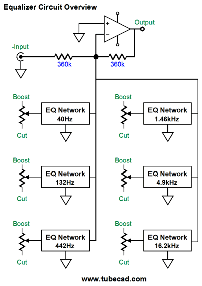
Tube Equalizer Part-2
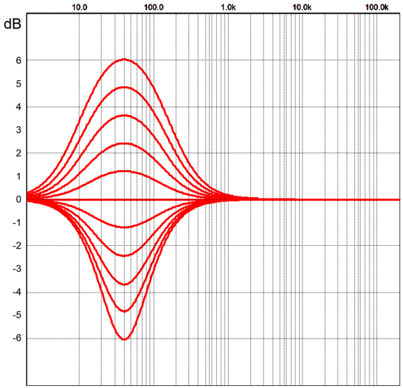
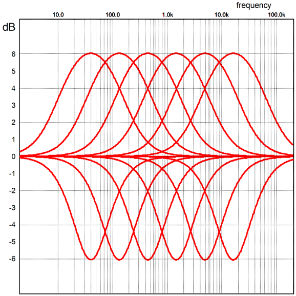
The equalizer steps are 1.2dB in size.
The center frequency was 40Hz. Here all the extreme settings.
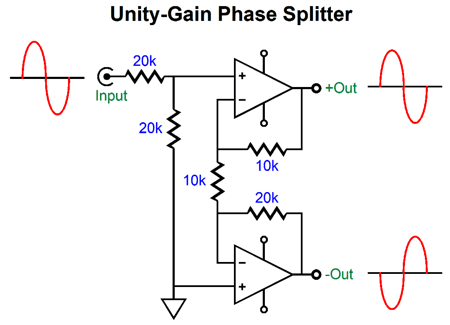
Many CD players and stand-alone DACs sport a set of output XLR jacks, which proves a handy source of input balanced signals. What if you run an all-analog system with turntable and phono preamp that only offers an unbalanced output signal? Well, in this case, we will need to build a phase splitter. Making a phase splitter out of OpAmp is easy. All that is needed is dual OpAmp that is unity-gain stable, such as the OPA2107 or XXX, and five resistors.
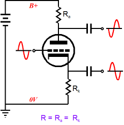
The two 20k resistors at the input define a two-resistor voltage divider with a 50% attenuation of the input signal. The two OpAmps are configured to develop a gain of 2, so the balanced outputs are at unity gain. For example, an input signal of +1V becomes +1V and -1V at the phase splitter's outputs. With tubes, we can make a phase splitter with just one triode, the split-load phase splitter.
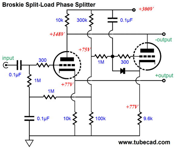
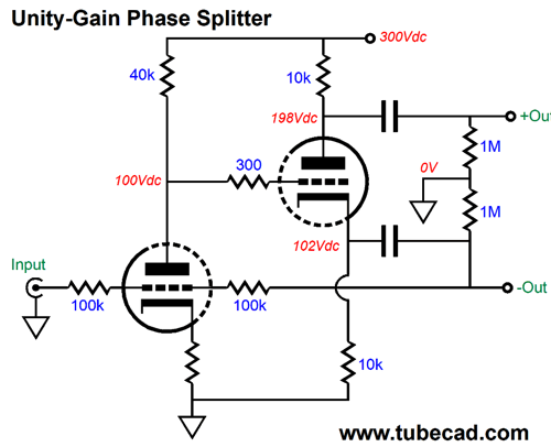
This simple phase splitter works amazingly well, but it is not perfect, as it loses some signal gain and the inverting output offers a far poorer PSRR than its non-inverting output. (The dissimilar output impedances are a non-issue in this application, as they are in most applications.) We can tackle the poor PSRR by using a Broskie split-load phase splitter, which appeared in 2012 in post 196.
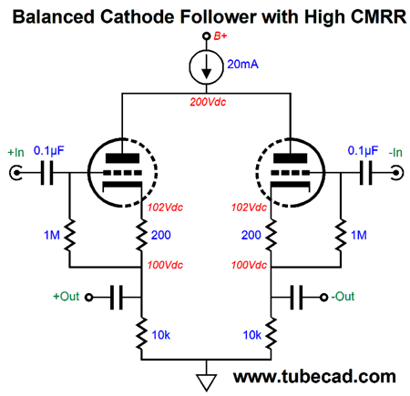
The triode on the left does the phase splitting, while the triode on the right greatly improves the PSRR by purposely treating 100% of the power-supply noise as its input signal, which prompts an anti-phase current flow through the shared plate resistor, resulting in a power-supply-noise null at the inverting output. (Read post 196 for the full explanation.) The next step would be to drive a differential pair of cathode followers with high CMRR.
By tying the two plates together and loading them with a constant-current source we force a strict balance on the two cathode followers, as an increase in conduction by one cathode follower must be balanced by an equal decrease from the other cathode follower. Well, a large-valued shared plate resistor comes close. See post 379 for more details. We stitch the two sub-circuits together thus:
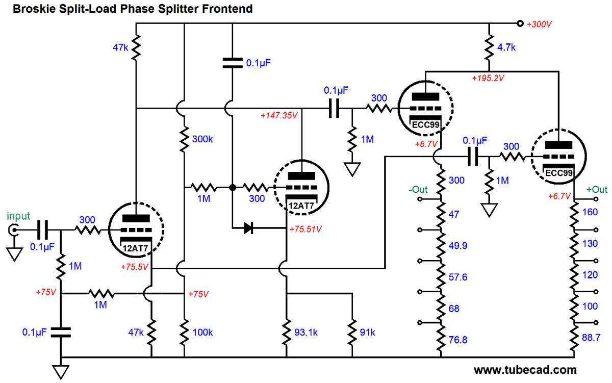
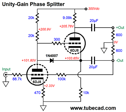
The ECC99-based cathode followers provide a low output impedance and the 12AT7's relatively high amplification factor (mu) gets us closer to unity gain. Still, we can expect more gain loss due to the cathode followers working into such a low resistance (600 ohms). The workaround is to add an input gain stage to the standard split-load phase splitter and apply a negative feedback loop.
I am amazed that I have sat on this circuit for decades without having had the cause to show it here. In spite of it looking as if it shouldn't work, it works extremely well. The single negative feedback loop works on both output signals, as the split-load phase splitter's plate and cathode resistors share the same and only current path from ground to the B+ voltage. If we vary the current flow through the cathode resistor, we vary the flow through the plate resistor. Let's flesh out the actual part values and voltages in a design example.
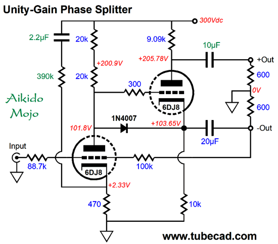
The 40k plate resistor has been replaced by two 20k resistors. Why? They don't make 40k resistors and the plate resistor will dissipate 1W, so two 20k/1W resistors will prove a better fit; in addition, the two resistors will give rise to less distortion, albeit a slight decrease. The diode protects the split-load phase splitter triode at turn-on, as it limits the maximum cathode-to-grid voltage to about+0.7V; in contrast, when the triodes are cold, the secondary triode would see a 300V differential, not good. The input resistor is no longer 100k, but 88.7k, as this value works to establish unity gain. The 100k negative feedback loop resistor is effectively in parallel with the split-load phase splitter's cathode resistor, making a combined value of 9.09k, so that is the value of its plate resistor. Alternatively, we could still use the 10k value and place a 100k resistor in parallel with the top 600-ohm load resistance. I prefer the lower-valued plate resistor approach, as it allows to gain a bit more cathode-to-plate voltage for the split-load phase splitter's triode. What's missing is some Aikido mojo. The problem, however, is that the mojo assumes a balanced circuit at the receiving end, such as push-pull output stage or balanced line-stage amplifier. Here is an example.
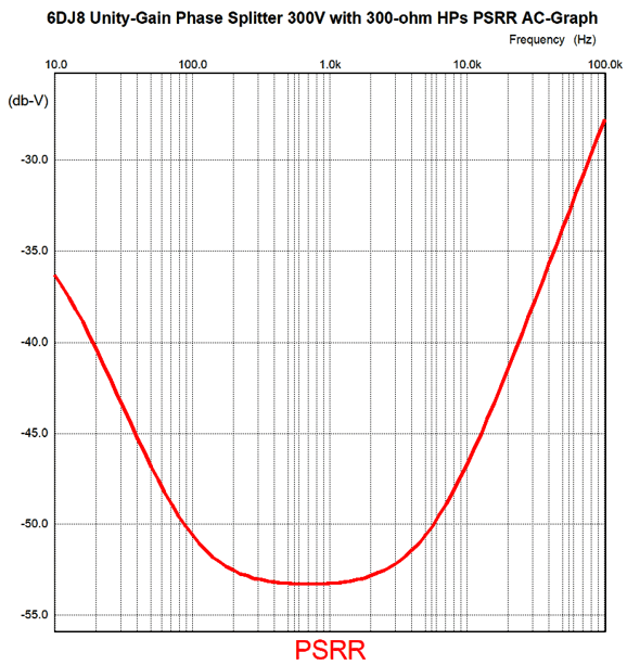
The PSRR is -30dB from either phase output to ground. In contrast, from output to output the PSRR is closer to -75dB from 10Hz to 10kHz, which is amazing. The equalizer circuit, however, is not a balanced circuit, so common-mode signals are not rejected, so we are stuck with the -30dB PSRR figure. Nonetheless, this is huge improvement over the stock split-load phase splitter.
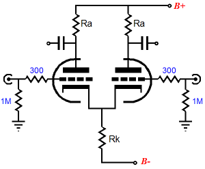
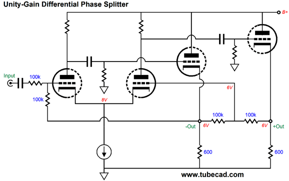
Another phase splitter topology is the differential long-tail circuit, which we can make better by replacing the shared cathode resistor with a constant-current source.
A negative feedback loop sets the gain to unity and the constant-current source gets enough voltage headroom within which to work due to the two cathode followers delivering the bias voltage to the differential input stage. Note the input coupling capacitor and how the negative feedback resistor DC couples to the cathode follower on the left. Alternatively, we can DC couple the input by terminating the negative feedback resistor after the output coupling capacitor.
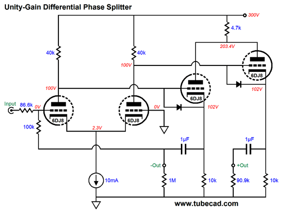
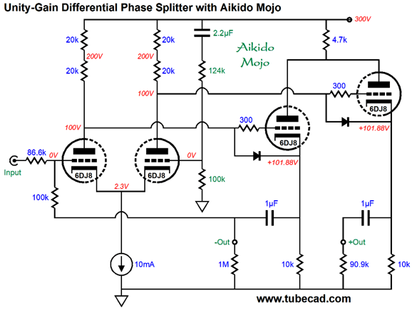
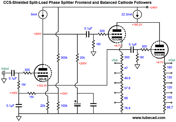
Two 6DJ8 tubes are needed per channel. The triodes in the input stage run 5mA each, while the triodes in the cathode followers run 10mA each. Note that the right triode in the input differential stage sees its grid grounded. The 4.7k serves to limit the plate voltage on the two cathode-followers and improves the balanced output from them. Although the differential phase splitter offers many advantages, PSRR is not one of them. We can add Aikido mojo, but once again the PSRR enhancement is best realized when driving a balanced circuit.
The PSRR is fine from output to output, but—relative to ground—it is close to nonexistent. The sneaking approach is to inject a sampling of power-supply noise into the constant-current source, so we can null the ripple at the plates.
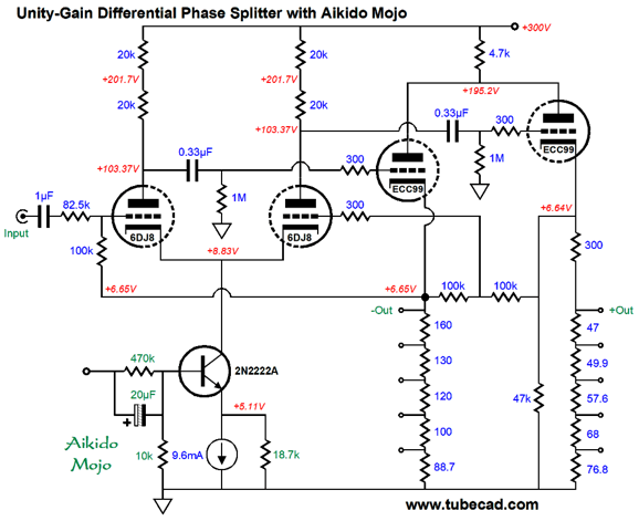
The NPN transistor sees all the AC power-supply noise at its base, which it then passes on to its emitter, an emitter loaded by the constant-current source in parallel with a high-valued resistor. The result is a modulation of the current flow through the transistor's collector that is destructive to the power-supply noise at the plates. For example, if the B+ voltage pulse up by 1V, that 1V pulse would be imposed on the emitter and the 18.7k resistor, which would force a pulsed increase in current flow through the transistor and the two triodes, causing the voltage drop across the 40k load resistances to increase by 1V. In other words, as the B+ voltage bounces up 1V, the voltage drop across the resistances increases by 1V, so the plates see no change in voltage. Conversely, when the B+ voltage drops by 1V, the voltage drop decreases by 1V, so the plates still see a fixed voltage. Since we have introduced a solid-state element, we might as well take further advantage of the constant-current source. For example, we can shield all the triodes from the power-supply noise by placing constant-current sources atop the plates. A constant-current source effectively acts like a high-inductance choke, except that it displaces voltage and dissipates heat, neither of which a perfect inductor would do.
The 6DJ8 input triode is configured as a split-load phase splitter, appearances to the contrary. In terms of AC signals, both its plate and cathode are loaded by 20k resistances. In DC terms, the current path from ground is through the 20k cathode resistor and then the triode and, finally, the constant-current source to the B+ voltage. Note the lower B+ voltage, only 240Vdc. Also note that the plate's 20k resistor dissipates no heat at idle, as it drops no voltage. In contrast, the 20k cathode resistor will dissipate 0.5W. The two ECC99 triodes are configured as high-CMRR cathode followers. Their shared constant-current source shields the plates from the power-supply noise and improves the balanced output.
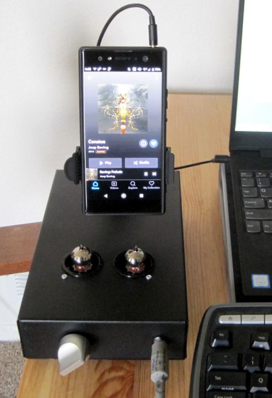
Not a Coffee-Cup Warmer In the photo, we see my Sony phone playing Tidal (the phone natively decodes MQA tracks). The phone holder was bought at a car-part store and it is meant to vacuum-mount on a car's dashboard. The vacuum seal has never broken loose; in fact, it takes some effort to break it.
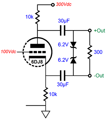
Split-Load Balanced Headphone Amplifiers
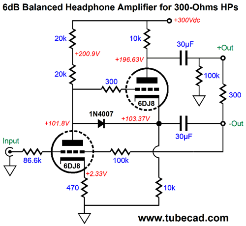
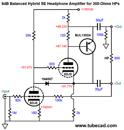
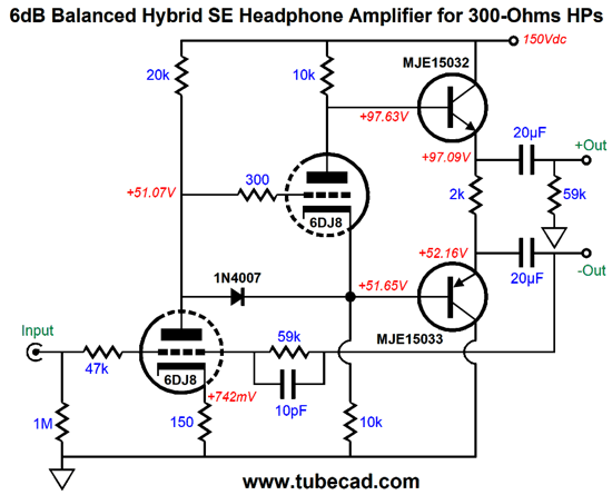
To make a useful tube-based headphones for driving 300-ohm headphones requires a heavy idle current flow from the split-load phase splitter, as this single triode must run in strict class-A, single-ended fashion.
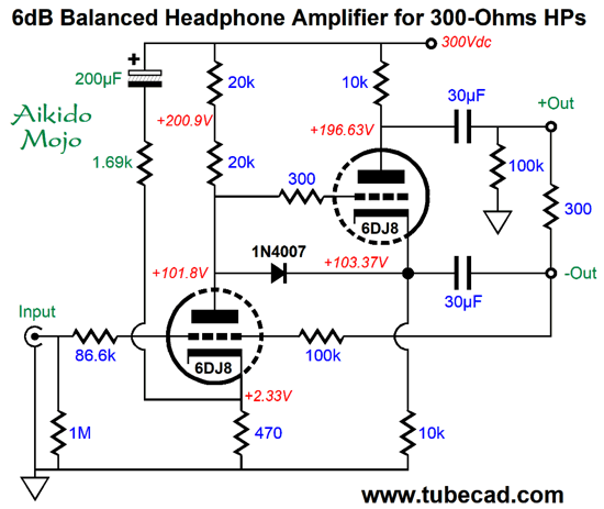
Here we see the grounded-cathode amplifier input stage delivering signal gain and receiving negative feedback from the inverting output. Without the feedback loop, much larger valued output coupling capacitors would be needed, as in 62µF each, as each coupling capacitor effectively sees a 150-ohm load. But as the negative feedback loop encompasses the bottom output coupling capacitor, the negative feedback restores the missing low-frequency bandwidth. Of course, nothing stops us from using the bigger coupling capacitors. Note that the input resistor is 86.6k, not 100k, as the tubes offer only a fraction of the transconductance of solid-state devices. And, yes, the diode is there as a protection device for the split-load phase splitter triode at startup. By the way, it would hurt to add two clamping zeners across the two outputs, say 6.2V types, to protect the headphones from voltage bumps at startup and potential tube wiggling, which could break connections and result in huge output voltage spikes.
Note that the essential single-ended nature of the output stage, in spite of the balanced output signals. This means that the triode's intrinsic transfer curvature must be imposed on the output, resulting in a strong 2nd harmonic content, although the negative feedback will strive to undo its excesses. What is missing is some Aikido mojo.
The added resistor and capacitor inject a sampling of the B+ voltage ripple into the grounded-cathode amplifier's cathode, which will paradoxically increase the amount of ripple on its plate, but reduce the ripple differentially across the two outputs. (Headphone drivers are intrinsically differential devices that ignore common signals at both terminals, but do respond to differences.) The electrolytic capacitor's value might seem too large, but it must be big in order to extend the power-supply null down to 100Hz.
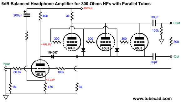
Now, a B+ voltage of 300Vdc is dang hot, but we need to get enough current flow from the output triode, which requires a large cathode-to-plate voltage. One workaround would be to place several, say three, triodes in parallel.
In theory, each of the output triodes should get its own 10-ohm cathode resistor; in practice, we can get away without them, as the 6DJ8 triodes are not nearly as prone to current hogging as transistors are. Another workaround is to add some solid-state help.
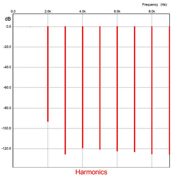
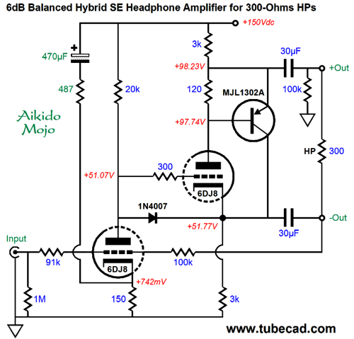
Note that the B+ voltage is now only 150Vdc. The PNP transistor, an MJL1302A, is a robust power transistor that is used in many high-end solid-state power amplifiers. The right triode and the transistor define a compound pair, with the transistor enslaved by the triode. I just spotted that I made a schematic boo-boo, as they don't make 92k resistors; the value should have been 91k. (About ten years ago, I made a similar typo, typing 283 ohms, not the correct 383 ohms. I then received email asking where a 283-ohm resistor could be bought. I explained the situation and few readers insisted that they wanted the 283-ohm resistor anyway, as they had read on some forum that it was the "hot" value. My faith in democracy wasn't strengthened.) We can view this setup as a super-triode configuration, as the triode draws close to constant current, while the transistor does the big current variations. Speaking of current, the idle current through the output stage is a tad over 25.9mA, which implies a peak output voltage swing 7.7V across the 300-ohm load. Realistically, 6V peak is closer to the actual limit. If we desire larger voltage swings, we must lower the split-load phase splitter's plate and cathode resistor values. This is something I would be hesitant to do. Why? I don't blast my headphones and I love the SPICE-generated Fourier graph for the present setup.
Note how the 3rd harmonic is so strongly attenuated. You know what is missing: Aikido mojo.
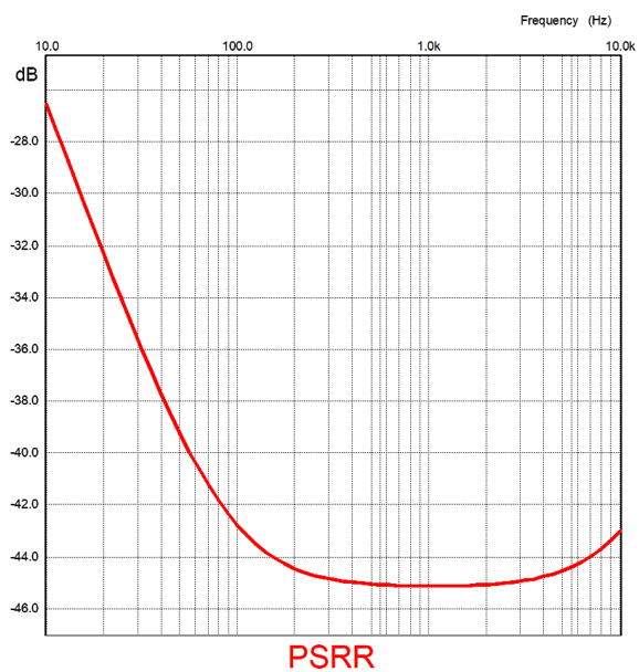
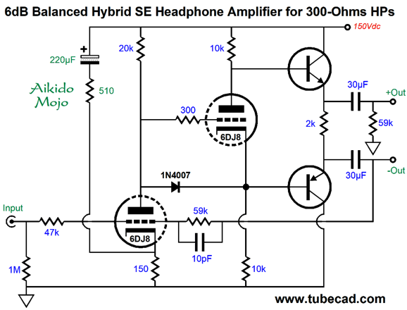
Since we are running a lower B+ voltage, we can get away with using a larger-valued terminating capacitor for the Aikido mojo resistor. Here is the PSRR graph for the circuit shown above.
Here in Northern America, the wall-voltage frequency is 60Hz, so most of the ripple will appear at 120Hz. Here is another variation.
And with Aikido mojo.
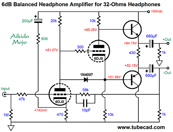
What about driving 32-ohm headphones? We could but I would use a pure solid-state output stage.
It looks push-pull, but it isn't, as both transistors run in current phase, not anti-phase, a requirement for push-pull operation. In other words, we should still expect a strong 2nd harmonic flavor, in spite of the two transistors. I aimed for an output stage idle current of 100mA, and the SPICE simulation revealed 99mA. Close enough. We should expect at least 3V peak voltage swings into a 32-ohm load, which equals 140mW of output power. The high idle current will force a 4.3W heat dissipation from the 430-ohm load resistor and a little over 5W from each transistor. If we desire more output power and less heat, we have to get extra clever, such as the following:
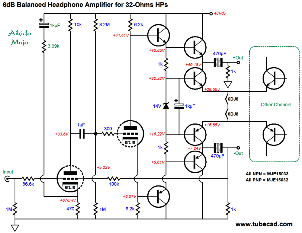
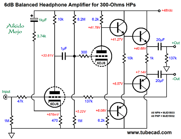
First of all, note the low 48Vdc B+ voltage, not 150V. Also note that the output transistors are driven by complementary emitter followers, which will greatly unload the triode-based split-load phase splitter. The two output transistors work into a constant-current source loads, which were created by using the tube heaters as power resistors. In other words, a free heater power supply. Both channels share the two 6DJ8 heaters in series. Thus, each channel sees constant-current source draws of 182mA. Since the B+ voltage is so low, we can use non-polarized electrolytic capacitors as the output coupling capacitors. (Of course, we could and should bypass them with quality film capacitors.) The power supply can be a 48V tabletop switcher. Actually, I would find a 56V switcher and place an RC filter in series with it and the headphone amplifier, say a 5W 20-ohm power resistor and a 63V 1kµF capacitor. The zener ensures that the two heaters never see excessive voltage. What about a low-voltage version for driving 300-ohm headphones? The circuit above would have no problem powering 300-ohm headphones, but if we sought to lower the idle current then the following would work.
A resistor, not tube heaters and constant-current sources, forms the resistance loading for the output transistors. What heats the heaters? We could use a second 12Vdc switcher power supply with a different sized plug termination, so that the 48V and 12V connections could not be confused; or, rather, although the 12V power supply could be plugged into the B+ voltage jack, the 48v power supply could not plug into the heater jack.
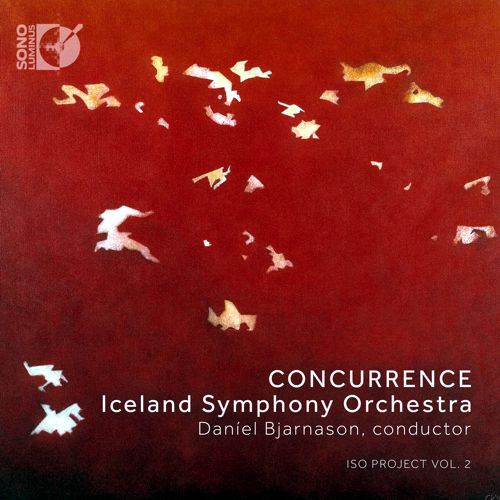
Music Recommendation: Concurrence Concurrence, is a new album by the Iceland Symphony Orchestra, conducted by Daníel Bjarnason, which holds four compositions by four Icelandic composers. The website, allmusic.com, lists the albums moods as:
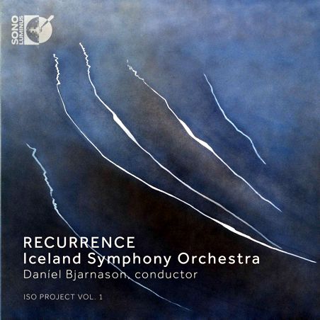
(I wonder how many would describe me with these same adjectives.) It took me two listens to realize how much I enjoyed hearing the album. If nothing else, it serves a system demo album. By the way, it is the second album of a set, the first is titled, Recurrence, which I plan on hearing soon. Both albums can be found at Tidal and Amazon Music, the difference being that latter offers them in 24-bit, 196kHz high-res format; the former, only in 16-bit, 44.1kHz CD grade.
Quick update, I listen to the Recurrence album last night. Wow! Sadly, Amazon omitted the third track, Aequora, which I then heard on Tidal in CD quality. Gentlemen, turn on your sub-woofer amplifiers and warn your family that it is just music, not an earthquake.
//JRB
User Guides for GlassWare Software
For those of you who still have old computers running Windows XP (32-bit) or any other Windows 32-bit OS, I have setup the download availability of my old old standards: Tube CAD, SE Amp CAD, and Audio Gadgets. The downloads are at the GlassWare-Yahoo store and the price is only $9.95 for each program. http://glass-ware.stores.yahoo.net/adsoffromgla.html So many have asked that I had to do it. WARNING: THESE THREE PROGRAMS WILL NOT RUN UNDER VISTA 64-Bit or WINDOWS 7 & 8 or any other 64-bit OS. I do plan on remaking all of these programs into 64-bit versions, but it will be a huge ordeal, as programming requires vast chunks of noise-free time, something very rare with children running about. Ideally, I would love to come out with versions that run on iPads and Android-OS tablets.
|
I know that some readers wish to avoid Patreon, so here is a PayPal button instead. Thanks. John Broskie
John Gives
Special Thanks to the Special 86 To all my patrons, all 86 of them, thank you all again. I want to especially thank
I am truly stunned and appreciative of their support. In addition I want to thank the following patrons:
All of your support makes a big difference. I would love to arrive at the point where creating my posts was my top priority of the day, not something that I have to steal time from other obligations to do. The more support I get, the higher up these posts move up in deserving attention.
If you have been reading my posts, you know that my lifetime goal is reaching post number one thousand. I have 489 more to go. My second goal was to gather 1,000 patrons. Well, that no longer seems possible to me, so I will shoot for a mighty 100 instead. Thus, I have 14 patrons to go. Help me get there.
Support the Tube CAD Journal & get an extremely powerful push-pull tube-amplifier simulator for TCJ Push-Pull Calculator
TCJ PPC Version 2 Improvements Rebuilt simulation engine *User definable
Download or CD ROM For more information, please visit our Web site : To purchase, please visit our Yahoo Store: |
|||


| www.tubecad.com Copyright © 1999-2020 GlassWare All Rights Reserved |