| John Broskie's Guide to Tube Circuit Analysis & Design |
Post 237 08 July 2012
Janus was the Roman God of beginnings and endings, whose purview included doorways and gates. Unlike most Roman gods, Janus finds no Greek equivalent; Janus appears to be of Latvian origin. Usually, Janus is depicted with two faces, one looking forward, the other backward. The month January is named after Janus, as this month looks on the previous year and on the new year to come. The word "janitor" also comes from the god Janus, as they are the keepers of the hallways and doorways. Saint Peter is sometimes referred to as "the Janitor of heaven." And few would wish to be called janus-faced (hypocritical).
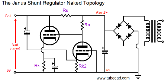
The Janus high-voltage regulator also looks two ways: towards the ripple from the rectifiers and to the signal-induced noise riding on the B+ rail. How this amazing feat is accomplished is a bit difficult to understand, as the following schematic shows.
In a typical tube-based shunt regulator, all the tubes would appear on the left side of the series resistor, Rs. But in the Janus regulator, the input triode is located on the rectifier side. Thus, it with its plate resistor define a two-resistance voltage divider, which gives the shunting triode on the left a sampling of the raw power-supply noise. Thus, if 50% of this noise is given to the shunting triode's grid, the series resistor must equal twice the shunting triode's rp divided by its mu. Because triodes offer relatively low transconductance, resistor Rs must be fairly large in value. This can prove a problem when high current flow is needed, as that high current will impose a large voltage drop across the series resistor. Another difficulty the Janus regulator faces is that the input stage, the triode on the right, which samples at its cathode the B+ noise induced by audio signal (and the little raw power-supply noise that makes it past the series resistor), is configured as a grounded-grid amplifier, with its input signal being delivered at its cathode and its grid grounded. In other words, the cathode's low impedance requires a very-large-valued capacitor to the B+ connection. Think electrolytic, not film. Let's start with the last difficulty. We can swap the shunt regulator's two topologies; thus, the input stage becomes a grounded-cathode amplifier and the shunting stage becomes a grounded-grid amplifier. This would allow us to use a small-valued capacitor to couple the B+ noise to the input stage's grid. One proplem solved, but a new one created. We cannot use a large-valued coupling capacitor to connect the input stage's plate to the shunting stage's cathode, as the input triode is likely to be a wimpy, high-mu triode, such as the 12AX7, while the shunting triode must be more of a brute, such as, at least, a 12AU7, and more likely a 6B4 or triode-connected power pentode, such as the EL84 or EL34. But by adding a high-voltage PNP transistor we can retain DC coupling and give the shunting triode the low-impedance input signal it needs to see at its cathode.
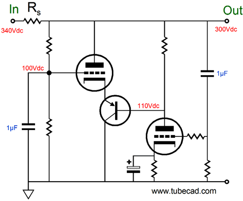
The power-supply noise present on the B+ output is relayed to the right triode's grid, which then gets greatly amplified and inverted at this triode's plate. The PNP transistor conveys the amplified and inverted noise signal to the shunting triode's cathode. For example, if a positive pulse appeared on the B+, the input triode will create a much larger negative pulse at its plate, so the shunting triode will see its cathode voltage drop hugely relative to its grid, which is locked to ground through the 1µF capacitor. The result is that the shunting triode's conduction increases greatly, forcing a bigger voltage drop across the series resistor, thus countering the positive pulse. The above schematic shows, however, a hybrid shunt regulator that is excellent in many ways, but it is not a Janus, as it only looks in one direction, towards the B+ connection. Converting the above circuit into a Janus style regulator requires flipping one capacitor's termination, so the shunting triode's grid is "grounded" at the raw B+ noise, not ground.
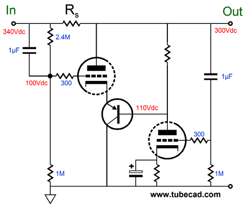
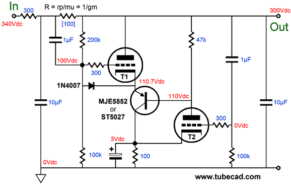
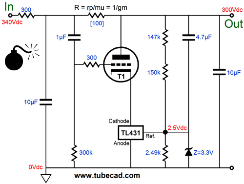
The shunting triode's grid now sees 100% of the raw power-supply noise after the rectifiers. And if the series resistor Rs is selected to match the inverse of the shunting triode's transconductance, the raw power-supply noise will be perfectly nulled out of existence on the triode side of the series resistor. For example, assume a gm of 10mA/V and series resistor of 100 ohms. If 1Vpk of positive pulse appears on the raw power-supply side of the series resistor, the shunting triode's current conduction will increase by 10mA, which provoke a 1V greater voltage drop across the 100-ohm series resistor. Thus, the output side of the series resistor will never see the 1V pulse. Note that this hybrid Janus regulator only strips away AC noise; it does not strive to maintain a fixed DC output voltage. Often, this attribute is not needed, as most low-level audio signal processing involves class-A stages, so the peak current draw equals the average current draw. Besides, most tube circuits are pretty much indifferent to 20V changes in their B+ voltages, say 280Vdc compared to either 260Vdc or 300Vdc. In contrast, a solid-state circuit that expects to see +24Vdc will be most unhappy with either 4Vdc or 44Vdc of B+ voltage. (Of course the percentage of difference are not the same.) In addition, making a shunt regulator put out a fixed DC voltage is often fraught with difficulties, as small shifts in the wall voltage or variations in the expected load current can either turn off the shunting triode or send it into meltdown mode. For example, if the wall voltage is only 5% higher than expected, the raw DC voltage will climb to about 357Vdc, causing triode T1 to quadruple its current conduction (and dissipation); if 5% lower, down to 323Vdc, causing triode T1 to cease conducting altogether. Nonetheless, if we are stubborn, we can make a fixed-DC Janus hybrid regulator, as the following schematic shows.
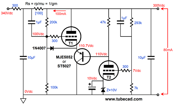
For any voltage regulator to maintain a fixed DC output voltage it must include a voltage reference. Sometimes the reference is hard to spot, but in the above Janus shunt regulator it is easy to spot, as it is the 10V zener. (The higher the break voltage of this zener, the more accurate the fixed output voltage becomes.) Triode T2 uses the fixed 10Vdc at its cathode to evaluate the DC voltage at the regulator's output. If the DC voltage is too high, then triode T2 will conduct too much current, forcing triode T1 to conduct even more until the DC output voltage is brought in line with the target voltage. Note how the series resistor Rs is in series with the 300-ohm resistor. Why? We need a total of 400 ohms of resistance and we need only 100 ohms for resistor Rs, so 300 ohms equals 400 ohms minus 100 ohms. In addition, the 300-ohm resistor with the 10µF capacitor will define an RC filter that nicely pre-filters the raw power supply noise, giving T1 less work to do. Note that triode T2 draws 4mA at idle and T1 draws 16mA, while the external load draws 80mA, for a total of 100mA, which across the 400-ohms of resistance in series with the raw DC creates a 40V DC voltage drop. If the external load is removed from the circuit, triode T1 will have to draw 96mA in order to maintain the 300V DC output voltage. Conversely, if the external load draws too much current, say 100mA, triode T1 will shut off completely, as the regulator strives to pull up the DC output voltage by decreasing T1's conduction. In other words, you can readily see why I don't think that a fixed DC output voltage is the way to go. On the other hand, if we forgo DC regulation, satisfying ourselves with active AC noise elimination, we face the potential problem of excess or inadequate current draw through triode T1. This problem arises due to the DC coupling within the Janus hybrid regulator. The workaround is to add an internal coupling capacitor. Icky. Or we could apply some negative current feedback between the two stages, which would work to establish a more steady current draw through triode T1.
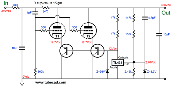
In the above example, both triodes T1 & T2 share the same current path to ground through the 100-ohm resistor. (This common resistor should have been 150 ohms to it in line with the previous example of 20mA of current flow for both triodes.) If too much current flows through T1, it will work to turn off T2, which will in turn work to greatly turn off T1. If T1 draws too little current, T2 will draw more current, forcing T1 to draw even more current. This negative feedback loop strives to keep triode T1's idle current fixed. The large-valued capacitor that shunts the 100-ohm resistor shunts away the AC currents flowing through the two triodes. The 1N4007 diode was added as a safety device that protect triode T1 at turn on, when the tubes are cold and not conducting or if T2 is pulled from its socket. (We do not want T1's grid to see a positive voltage relative to its cathode.) Another current feedback setup would be to sample the current flowing through triode T1 at its plate.
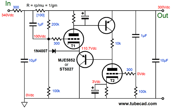
The topmost PNP transistor holds an effective voltage reference in its well-established base-to-emitter voltage. If this voltage is exceeded, the transistor conducts wildly; if it falls below, the transistor cuts off and stops conducting altogether. Thus, this PNP transistor will strive to establish the exactly right base-to-emitter voltage, constantly working to ensure that triode T1 conducts just enough current to establish the exact 0.7V voltage difference between its base and its emitter. If triode T1 conducts too much current, this transistor will also conduct too much current, forcing T2's plate voltage to rise, thereby increasing T1's cathode voltage, which will serve to reduce T1's current conduction. A negative feedback loop, in other words. The large-valued capacitor that shunts T1's plate resistor steals away the AC signal from the transistor's base, so it only sees the near DC shifts in voltage, not AC signal. In other words, we have setup an auto-bias circuit for triode T1. Its plate resistor divided into 0.7V roughly equals its idle current. In addition, the topmost PNP transistor will effectively function of a constant-current source of sorts, increasing T2's gain and improving its PSRR and improving the entire circuit's performance. Both of these current feedback schemes are, however, completely incompatible with creating a fixed DC regulator. Still, I know that many absolutely desire a tube-based shunt regulator that puts out a fixed DC voltage. Well, the following circuit might work out, if everything goes as planned.
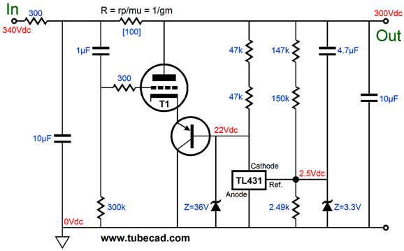
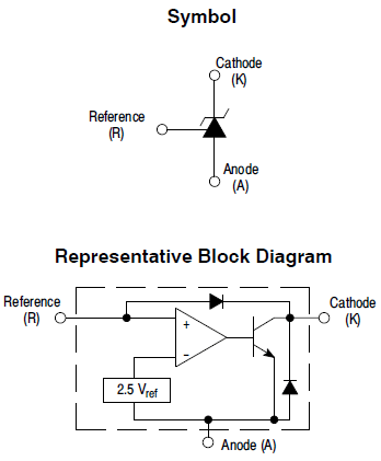
The input tube has been replaced by the the TL431 IC shunt regulator. This small, three-pin, solid-state device strives to maintain a fixed 2.5Vdc voltage at its reference pin. If the voltage falls short, the TL431 conducts less; if too high, it conducts more. Triode T1 conducts in current phase with the TL431, so the triode allows the little device to control the triode, which does the heavy work of keeping the DC output voltage fixed. (The 36V zener is a protection device for the TL431, as is the 3.3V zener.)
No doubt, some are thinking that the this hybrid Janus regulator circuit can be simplified by placing the TL431 in cascode with the triode. It can't. nonetheless, here is what this idea looks like.
What's the problem? The TL431 is good for up to 37V and 100mA, so why shouldn't it work? The problem is that this regulator only looks one way, towards the external load, as the TL431's cathode presents a very high impedance to the triode's cathode, not the very low impedance it needs to see. One last variation. Although big beefy power triodes do exists, such as the 2A3 or 300B or 6C33, they tend to be expensive and large. Most tube-loving audiophiles prefer small dual triodes. Well, a 5687 or ECC99 or 6H30 could be used as the shunting triodes in the following circuit.
Next Time
//JRB |
I know that some readers wish to avoid Patreon, so here is a PayPal button instead. Thanks.
John Broskie
And
High-quality, double-sided, extra thick, 2-oz traces, plated-through holes, dual sets of resistor pads and pads for two coupling capacitors. Stereo and mono, octal and 9-pin printed circuit boards available.
Designed by John Broskie & Made in USA Aikido PCBs for as little as $24 http://glass-ware.stores.yahoo.net/
The Tube CAD Journal's first companion program, TCJ Filter Design lets you design a filter or crossover (passive, OpAmp or tube) without having to check out thick textbooks from the library and without having to breakout the scientific calculator. This program's goal is to provide a quick and easy display not only of the frequency response, but also of the resistor and capacitor values for a passive and active filters and crossovers. TCJ Filter Design is easy to use, but not lightweight, holding over 60 different filter topologies and up to four filter alignments: While the program’s main concern is active filters, solid-state and tube, it also does passive filters. In fact, it can be used to calculate passive crossovers for use with speakers by entering 8 ohms as the terminating resistance. Click on the image below to see the full screen capture.
Tube crossovers are a major part of this program; both buffered and un-buffered tube based filters along with mono-polar and bipolar power supply topologies are covered. Available on a CD-ROM and a downloadable version (4 Megabytes). |
|||


| www.tubecad.com Copyright © 1999-2012 GlassWare All Rights Reserved |