| John Broskie's Guide to Tube Circuit Analysis & Design |
04 January 2023 Post Number 574
Happy New Year!
Six Power Amplifiers Powered by One Power Transformer In addition, the power transformer must be a readily available one, not a custom design with multiple secondary taps. Here is what I came up with:
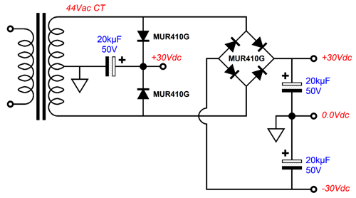
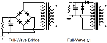
The power transformer offers a modest 44Vac center-tapped secondary. Two rectifier circuits are employed, both full-wave rectified. The first rectifier circuit holds only two ultra-fast rectifiers, which creates a 30Vdc monopolar power-supply rail. This is the rectifier-circuit topology used in most tube-based amplifiers that use a tube rectifier, and it is called the full-wave center-tap configuration. It uses only half of the secondary winding at a time and requires a center-tapped winding and two rectifiers, saving two compared to the full-wave bridge configuration.
On the other hand, the two rectifiers will see twice the peak reverse voltage that four rectifiers would see in a full-wave-bridge configuration, which can greatly limit the use of solid-state rectifiers in high-voltage power supplies; in addition, the transformer is only about 75% as effectively utilized in this configuration compared to the full-wave-bridge circuit. Paradoxically enough for what many consider a purely high-voltage circuit, this rectifier circuit is often used in extremely low-voltage power supplies, as the single-diode voltage drop greatly increases this circuit’s potential output voltage due to a single rectifier voltage drop. The second rectifier circuit uses four rectifiers, and is named the full-wave-bridge-rectifier circuit. Without a secondary center-tap, the circuit yields a monopolar DC voltage; with a center-tap, a bipolar positive and negative power-supply rails. Because the entire secondary winding is always being utilized, this is a more efficient rectifier circuit. Roughly, we can expect to get 75% to 78% of the power transformer's VA rating as useable power. For example, a 100VA power transformer would deliver 75W of rectified DC output. In my last post, I laid out one possible array of power amplifiers that would conform to the decreasing need for power above about 500Hz. Here is what I said:
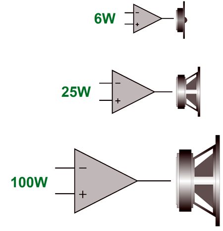
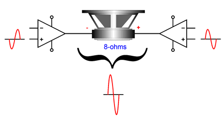
Well, here is another possible arrangement, 160W for the woofer, 40W for the midrange, and 9W for the tweeter. No doubt, only the 40W amplifier makes sense with the bipolar power supply I have outlined here, as 40W into an 8-ohm load resistance requires 25.3V of peak voltage swing, which would fit comfortably within the +/-30Vdc bipolar power-supply rail voltages. So, just how do we get 160W from this power supply? Answer, we use a bridge amplifier that will double the output voltage swings across the woofer, making for 160W, as (25.3 + 25.3) ² / (2 · 8) = 160. See post 407 for a full explication of how a bridge amplifier works.
Since a bridge amplifier uses two internal power amplifiers, and since the midrange and tweeter each get one amplifier, how did I come up with the number six? Answer: the bridge amplifier would hold four power amplifiers, not two. Let's start with a simple two-amplifier bridge amplifier
When a bridge amplifier drives an 8-ohm loudspeaker, each internal power amplifier sees a 4-ohm load, not an 8-ohm load. Driving a 4-ohm load is twice as hard as driving an 8-ohm load, but by doubling up on the bridge amplifier's usual two amplifiers, each of the four internal amplifiers will effectively see an 8-ohm load.
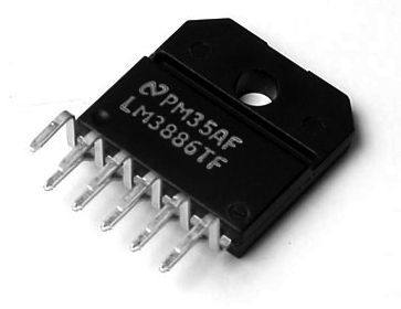
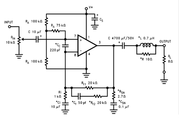
What I had in mind when I drew this schematic for post 386 was to use four power chip amplifiers, such as the famous LM3886, for the woofer and midrange.
The LM3886 is a fine sounding solid-state power amplifier, which we find being used in some very expensive high-end power amplifiers. It benefits from being so small, relative to a comparable solid-state power amplifier made from discrete parts. But it also suffers from being so small, as its thermal resistance to the heatsink is high, relative to a comparable solid-state power amplifier that holds at least two TO-3 or TO-247 packaged output transistors. In addition, the two separate output transistors would be spaced a few inches apart, which makes better use of the heatsink's ability to cool. In contrast, the LM3886 concentrates the heat at one spot on the heatsink. By using four LM3886 amplifiers for the bridge amplifier, however, we effectively quarter the thermal resistance and spread the heat out over more of the heatsink. In addition, in a powered loudspeaker, the LM3886 ICs will be trapped within the enclosure, surrounded by a warm blanket of sound-absorbing material. The midrange would get one LM3886, which can put out a bit over 40W with +/-30Vdc power-supply rails. This leaves the tweeter and its 9W single-ended class-A amplifier. Now, 9W may not sound like much power, but with a typical high-SPL tweeter and the limited amount of musical energy produced at high frequencies, the 9W amplifier may never clip. Well, how do we design a 9W solid-state SE amplifier?
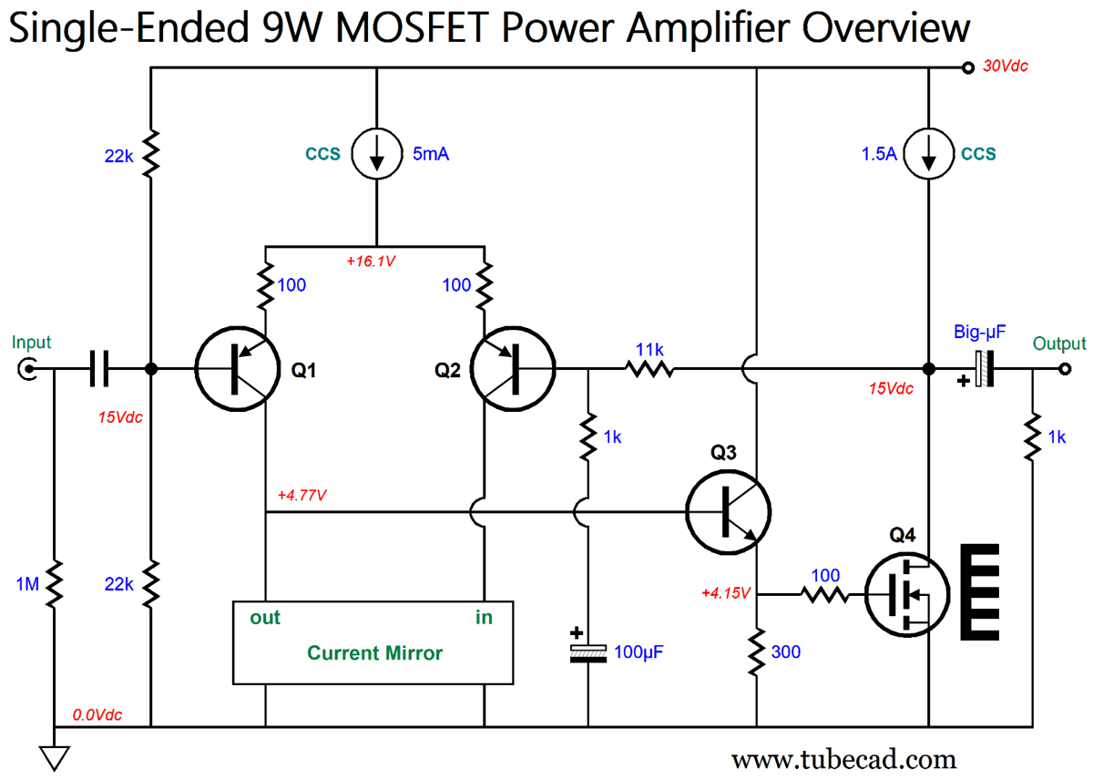
Single-Ended 9W Solid-State Amplifier
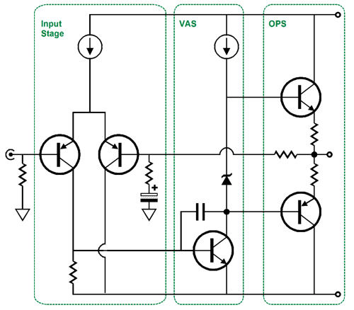
With power amplifiers, we should work backwards, starting with the output stage. This output stage holds a single power MOSFET (Q4) loaded by a 1.5A constant-current source. As the power supply does not offer a negative voltage rail, the input and output must be capacitor coupled. The MOSFET's gate is driven by an emitter follower stage (Q3) that easily drives the gate-to-drain capacitance. The input stage consists of a PNP-transistor-based differential amplifier that is loaded by a current mirror. In many ways, this topology looks like a standard three-stage solid-state amplifier based on the design work of Mr. Hung Chang Lin of RCA, whose 1950's design has conquered the solid-state amplifier world, as 99.99% of solid-state amplifiers are based on his three-stage design.
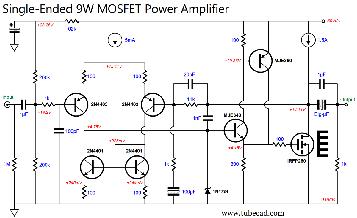
The Lin topology holds an input stage, a voltage-amplification stage (VAS), and an output stage, usually a voltage-follower stage that delivers no voltage gain, but does deliver huge current gain. The key requirement for the input stage is linearity, not gain, as it is the VAS that will deliver the bulk of needed signal gain. The differential input stage places the inverting (Q1) and non-inverting (Q2) inputs at the same voltage potential, which makes for an easy application of negative feedback. Interestingly enough, the differential input stage functions as a voltage-to-current amplifier (i.e. a transconductance amplifier), while the VAS gain stage functions as a current-to-voltage amplifier (i.e. a transimpedance amplifier), which converts the current swings into voltage swings to drive the output stage. In contrast, this 9W single-ended amplifier departs from the Lin topology in that there is no VAS gain stage; instead, it relies on the input stage and the output MOSFET to provide the needed gain, somewhat in the fashion of the Pass Zen amplifiers. This explains why no source resistor is used, as it would only subtract from the MOSFET's transconductance. For example, if a 0.1-ohm source resistor were in place, the MOSFET's effective transconductance could never exceed 10A/V. In fact, if a low-capacitance MOSFET (a SiC type, for example) were used, we could get away without using the emitter follower stage (Q3) altogether, making a two-stage power amplifier, not a three-stage amplifier. Okay, this has been the quick overview of a simplified schematic. Here is the full schematic. Well, it's almost "full," as the two constant-current sources remain mere symbols. What has changed is that the current-mirror circuit is fleshed out, and the output MOSFET gets a current-limiting protection zener (5.6V) that limits the maximum output voltage leaving the MJE340- and MJE350-based compound emitter-follower, so the MOSFET maximum current draw is about 5.5A. Without the zener, the MOSFET could draw up to 100A with a shorted output.
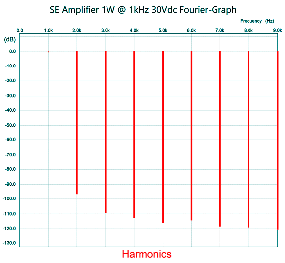
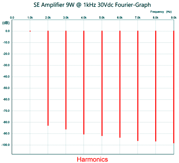
By the way, the output coupling capacitor makes this amplifier inherently far safer, as after the initial output current surge depletes the output coupling capacitor's charge, the output voltage would fall to zero. And when it comes to driving delicate tweeters, safety should be our first concern. Other enhancements to the design are the 20pF negative feedback capacitor and RC filtering of the two-resistor voltage divider voltage at the input and the input low-pass RFI filter. The 1nF (1,000pF) capacitor that bridges the output to the MJE340's base is there for the same reason it is in the VAS stage of the Lin topology, i.e. to limit high-frequency bandwidth and decrease high-frequency phase shift and Zo, thereby increasing high-frequency stability. One way to look at this amplifier topology is to imagine that it simply the first two thirds of a Lin topology, as the N-MOSFET is effectively a high-current VAS stage. As we would expect from a class-A amplifier, the distortion is low, with smooth cascade of harmonics. Here is the SPICE-generated graph of one watt of output at 1kHz (4Vpk). Next, we see the graph for full output, 9W (12Vpk) at 1kHz into an 8-ohm load.
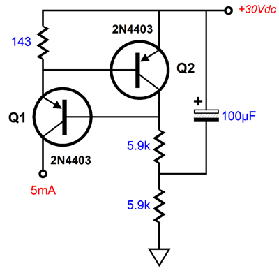
The 5mA constant-current source is easy enough to build.
Transistor Q2 monitors the voltage drop across the 143-ohm emitter resistor, making adjustments to transistor Q1's base voltage until the target voltage drop is achieved. Making the much higher current 1.5A constant-current source is going to require a bit more care.
High-Current Constant-Current Source
Well, I hope we all enjoy a smooth and strong current of domestic joy. Enjoying great music in our homes must be an essential part of that joy, which brings us back to the topic of constant-current sources. First of all, the name "constant-current source" is a misnomer, as the circuit does not create current; it is not a source of current generation, but rather regulates its flow, limiting it to fixed limit. In other words, a "constant-current source" should be called a "current regulator." Making a comparison to a voltage regulator is worthwhile. A voltage regulator strives to deliver a fixed output voltage in spite of a varying load current, thereby establishing a super-low output impedance. A current regulator works to deliver a fixed output current flow in spite of a varying output voltage, thereby presenting a super-high output impedance. In other words, they are inverse mirror reflections.
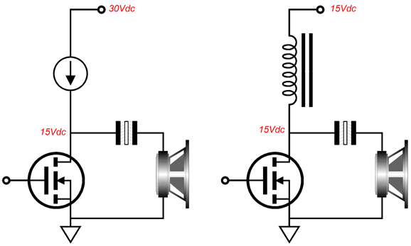
Sadly, we are stuck with the "constant-current source" label. In a solid-state single-ended output-stage loaded by a constant-current source, both the output device and the constant-current source will (usually) dissipate the same amount of heat. This results in the amplifier's meager 25% maximum theoretical efficiency. For example, to get 25W of output power requires an idle power dissipation of 100W. If we replace the constant-current source with an inductor, the output stage's theoretical maximum efficiency climbs to 50%, so only 50W of dissipation at idle. This assumes a perfect inductor, i.e. one that exhibits zero DCR. Remember, ideal reactive devices, such as capacitors and inductors and transformers, dissipate no power. Nonetheless, an actual inductor made from coiled copper wire around an iron core will still dissipate far less heat than a constant-current source.
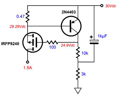
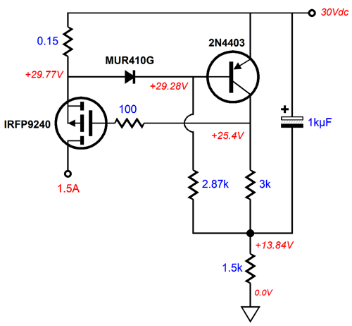
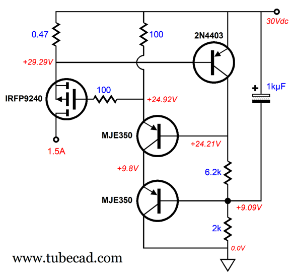
The easy way to make a high-current constant-current source is to use a power P-MOSFET and small PNP transistor, along with a few resistors and a capacitor. This circuit works amazingly well, in spite of its simplicity, as an impressive PSRR of -100dB at the critical 100Hz to 120Hz frequency range results.
The ripple frequency is twice the wall-voltage frequency with conventional rectifier circuits. The only real downside to this circuit is the wasted 0.7V voltage drop across the 0.47-ohm source resistor, which wastes heat and subtracts from potential amplifier output-voltage swing. (If the constant-current source draws 10A, the resistor would dissipate 7W). My workaround is to add a diode, whose forward-biased voltage drop will subtract from the regular 0.7V voltage drop.
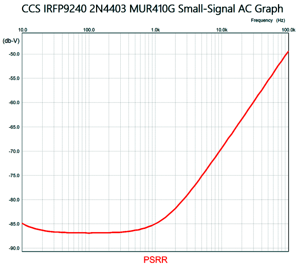
The 0.15-ohm resistor dissipates one-third the heat of the 0.47-ohm resistor and displaces only 0.23V. The voltage savings is not a big deal with a B+ voltage of 30Vdc, but it becomes a much larger savings when the B+ voltage is a wee 5Vdc. The PSRR is not as good as the previous version.
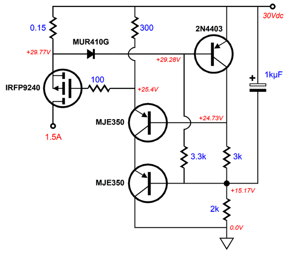
It's about 15dB worse, but it extends up a bit flatter in frequency. This becomes important when a switching power supply is used, as their ripple frequency usually falls between 40kHz to 100kHz. The following modification flattens the attenuation even further up in frequencies.
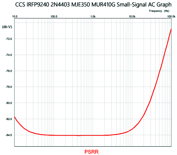
The cascoded emitter follower based on the two MJE350 transistors extends the flat portion out to about 10kHz, and offers a 16dB improvement at 40kHz over the first constant-current-source design.
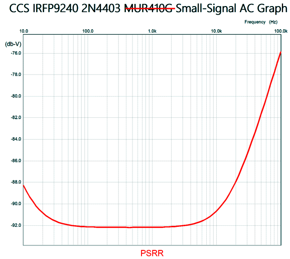
If we forgo the diode and use a 0.47-ohm source resistor, we get a decent 92dB PSRR that offers a respectable -83dB reduction at 40kHz. (Remember, the power supply reservoir capacitors will help shunt away high-frequency ripple. Just adding a 0.1-ohm RC-filter resistor will make a huge difference.)
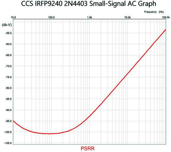
Here is the resulting PSRR graph.
If the graph's Y-axis were scaled to -10dB decrements, the plotline would look even more impressive.
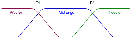
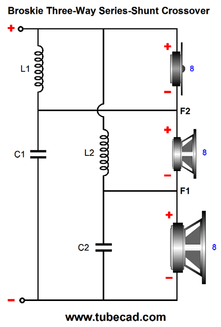
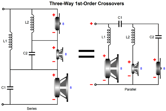
Active Three-Way Crossover
This series-shunt crossover improves upon the standard 1st-order parallel and series three-way crossovers with tweeter cascade by delivering an equally flat frequency phase response but also provides a woofer cascade, wherein the woofer sees both low-pass crossover frequencies.
In contrast, the two above crossovers only offer a tweeter cascade, so the woofer sees only the single low-frequency low-pass filter.
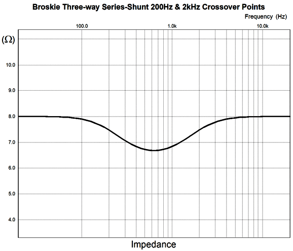
In other words, the passive series-shunt crossover provides both tweeter protection and gets the woofer out of the way at higher frequencies, making for a cleaner midrange. The series-shunt crossover comes at a small cost, as its impedance plot is not flat, incurring a slight dip in impedance at the middle.
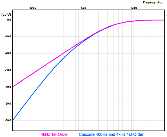
As you can see, the nominally 8-ohm loudspeaker impedance drops to about 6.8 ohms at 632Hz, the geometric mean between the 200hz and 2kHz crossover frequencies. This makes sense, as both the woofer and tweeter will be putting out less energy at that middle frequency, so the midrange must make up for their lower output, which means it must receive more power at the middle frequencies, which the dip in impedance accomplishes. Here are the plotlines for the tweeter with a single 4kHz high-pass 1st-order filter and with a 400Hz and 4kHz cascade.
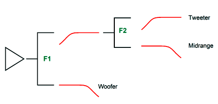
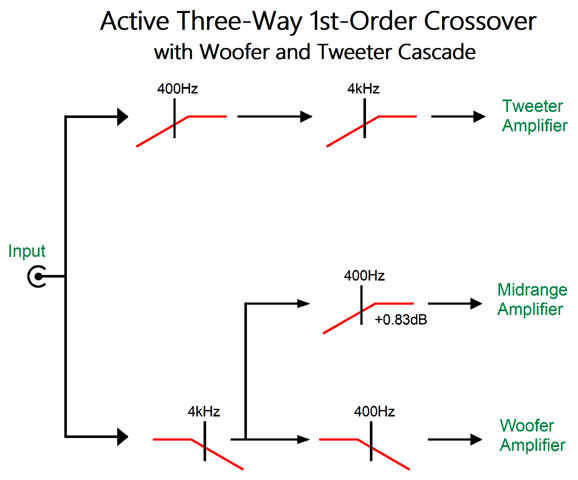
Note that cascading high-pass filters put the tweeter output down an additional -20dB at 40Hz. In other words, the tweeter experiences a tenfold reduction in signal at 40hz; relative to the woofer, the tweeter gets only 1/1000th the signal. Well, I have scratched my head trying to think of a simple active crossover analogy of the series-shunt three-way crossover. Here is the overview of what is needed.
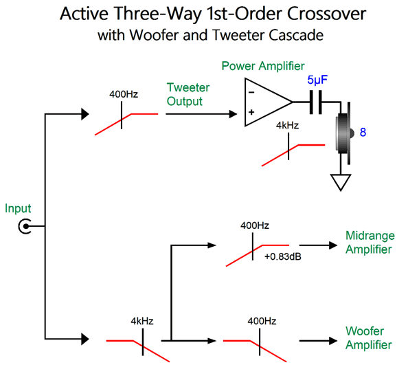
Note the midrange boost of 0.83dB, which can be realized by either using a midrange driver with 0.83dB great SPL or by adding a slight amplification of the midrange signal or by attenuating the woofer and tweeter signals by -0.83dB. Although I have mentioned many times before that when bi-amping or tri-amping, the tweeter must get a coupling capacitor to protect it from hum and thumps coming from the power amplifier, it is worth repeating. For example, say that the interconnect cable is jostled and break its ground connection to the tweeter power amplifier, the resulting full-power hum will quickly toast the tweeter. In contrast, if the tweeter connects to its power amplifier through a 5µF coupling capacitor, the 50Hz or 60Hz hum will be greatly attenuated. In addition, the 5µF coupling capacitor actually becomes part of the active crossover.
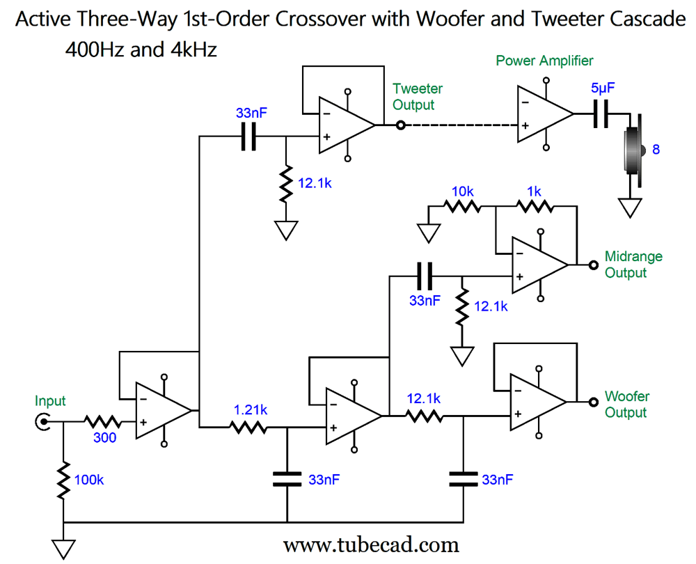
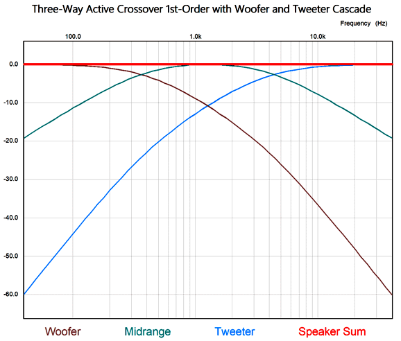
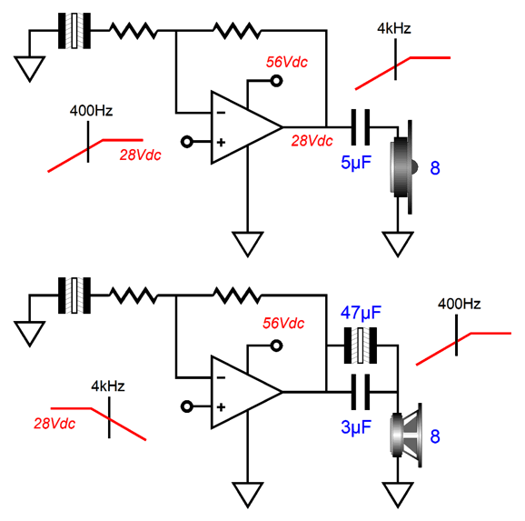
The tweeter sees an active 400Hz high-pass filter and a passive 4kHz filter, while the woofer and midrange see entirely active filters. Here is one way to implement the crossover. The input OpAmp serves as unity-gain buffer, which prevents a high output impedance from the signal source from throwing of the crossover frequencies. The input OpAmp then drives the two filters, a low-pass filter at 4kHz for the midrange and woofer; and a 400Hz high-pass filter for the tweeter. The midrange driver gets its slight boost from the OpAmp configured as an amplifier, with the 10k and 1k negative-feedback-loop resistors setting the gain to 0.83dB (1 : 1.1). Note that all the filters use a 33nF (0.033µF) capacitor. Why? It is easy to buy 1% capacitors in only a few values, with one of them being 33nF. Here is the SPICE-generated plotlines.
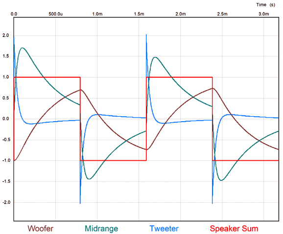
The three signals sum to a flat frequency and phase response. Note how both the woofer and tweeter slopes start out 1st-order, but then progress to 2nd-order. The real test is to see if the crossover will pass square waves. It does.
Note that the tweeter sees an initial spike twice the square-wave amplitude. No wonder that square-wave testing of loudspeakers and clipping low-power amplifiers often result in blown tweeters.
An All-Chip-Amplifier Loudspeaker
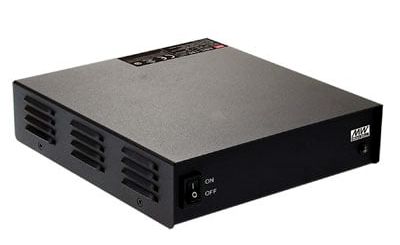
Since both the midrange and tweeter would be capacitor coupled, we could get away with a monopolar power supply. I own several 56Vdc desktop switching power supplies, but they only put out 1.16A, whereas something closer to 4A will be needed for the midrange amplifier. Jameco Electronics sells a 359W, 55.2V, 6.5A desktop switching power supply, a fan-less design that offers 8.2A of peak output current and an efficiency of 94% for only $104.10.
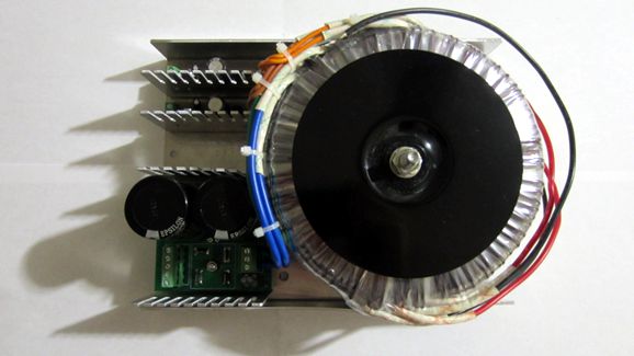
On the other hand, AnTek sells a toroid-based conventional power supply, the PS-5N56, that delivers 500W, a nominally 60Vdc power supply that delivers 56Vdc at 9A.
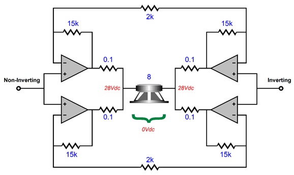
Okay, what about the woofer, surely it is not going to be capacitor coupled? Well, with the bridge-amplifier topology, we can get away with the monopolar power supply, as the woofer would never see a net differential DC voltage, even though both its voicecoil terminals would see 28Vdc at idle, assuming a 56Vdc monopolar power supply.
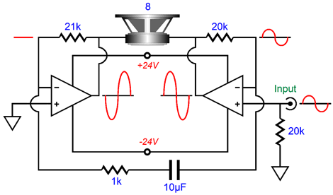
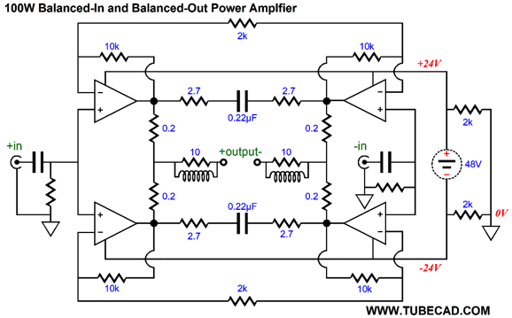
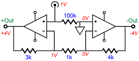
Each of the bridge amplifiers develops a gain of 1:16, so the differential gain across the woofer is 1:32. A balanced signal is needed, which is easy enough to create with OpAmps.
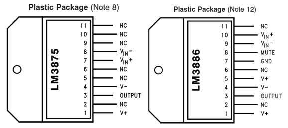
Speaking of things differential, since the woofer is an intrinsically differential device, much in the same way that the woofer completely ignores the 28Vdc at its terminals, it will ignore any common-mode signal, such as leaked power-supply noise. In other words, we will let the woofer take care of the task of common-mode rejection (CMRR). If you think that I am thinking of using four LM3886 amplifiers, you are close, as the actual power-amplifier IC I have in mind is the LM3875, a precursor to the LM3876 and LM3886. The pin-outs differ:
Comparing schematics and specs, however, it looks as if the LM3875 shares the exact same topology as the LM3886 minus the muting feature, this means that none of the LM3875 pins needs to be grounded (or referenced to half the B+ voltage of a monopolar power supply). This is a big deal in monopolar power supply. True the LM3886 can be used with a monopolar power supply, but only if we create a faux-ground circuit, as shown below.
Note the 2N3904 emitter follower that drives pin 7; in addition, resistor Rm is required with the LM3886 but not with the LM3875. In contrast, the LM3875 doesn't need to buffer half the B+ voltage, as a two-resistor voltage divider is enough (the two 100k resistors).
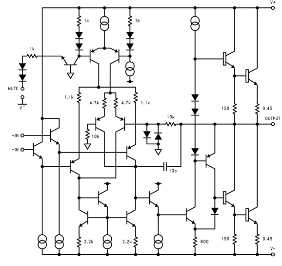
Mind you, the muting circuitry used in the LM3886 is dang clever, and could come in handy in certain applications. The way it works is that the LM3886 holds two input differential stages in parallel, both terminating into the current-mirror circuit, but only one works at a time.
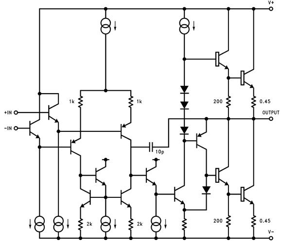
When in muting mode, the primary differential stage (the one with 1.1k emitter resistors) shuts down, as its constant-current source turns off, and then the secondary differential stage (with 4.7k emitter resistors) turns on as its constant-current source begins to conduct. The secondary differential stage's non-inverting input is grounded, and its inverting input attaches to the output through a 10k resistor, resulting in 100% negative feedback, transforming the amplifier into a unity-gain buffer with ground as its input signal. The outcome is that the amplifier's output goes dead silent. Compare the above LM3886 schematic to that of the LM3875 below:
I find it amazing how simple this circuit seems, now without the muting circuitry. By the way, all data-sheet schematics are simplified, for instance in these two schematics, all the anti-spike and protection circuitry has been stripped away. Another big difference between the devices is that the LM3875 is deemed obsolete, which means that we can buy them for a few dollars. For example, onestopelectro.com sells a cluster of ten of them for only $22.16. You cannot buy a single high-quality output transistor for $2.216, let alone a lateral MOSFET or output tube.
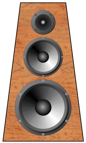
Okay, imagine a tall narrow loudspeaker enclosure that sports a long extruded aluminum heatsink on its back. Attached internally to the heatsink would be six LM3875 chip amplifiers. The internal power amplifiers allow us to escape resistor padding networks, crossover inductors, and many headaches. In addition, we can use wildly differing driver SPLs. Indeed, especially efficient midranges and tweeters would make their 40W amplifiers seem to be much more powerful. For example, a 6dB improvement in SPL is equal to quadrupling amplifier power. If one were truly ambitious, he would build an integral subwoofer with its own cluster of LM3875 amplifiers, making a four-way powered loudspeaker system. Actually, what would be more fun are separate subwoofer enclosures that would house the massive power supply to power all the internal amplifiers.
In contrast, we can think small. I would dearly love to hear a smallish active three-way loudspeaker that used three identical fullrange drivers, as this would grant us our best chance of the drivers seamlessly blending due to all the drivers exhibiting the exact same frequency response and phase plots. By the way, we could get extra fancy and use four of the fullrange drivers as the woofer, two for the midrange in a D'Appolito arrangement, and one for the tweeter. Such an arrangement would be a huge pain with a passive crossover and external power amplifier, as the four woofer drivers would develop a 6dB increase in SPL, while the two midrange drivers would result in either a 4-ohm or 16-ohm load, assuming 8-ohm drivers. With an active crossover and three power amplifiers, however, all these problems would disappear. Note that a 6dB boost in SPL means that the woofer amplifier's output power is effectively increased fourfold. Seven speaker drivers sounds like a lot of drivers, but if we used four-inch fullrange drivers, a narrow, three-foot tall loudspeaker cabinet would easily house them all. This might make for the perfect bedroom system.
Music Recommendation: Lautten Compagney, Time Travel Both Amazon Music and Qobuz offer this album in 24-bit 96kHz.
//JRB
Did you enjoy my post? Do you want to see me make it to post 1,000? If so, think about supporting me at Patreon. The more support I receive, the more I can post.
User Guides for GlassWare Software
For those of you who still have old computers running Windows XP (32-bit) or any other Windows 32-bit OS, I have setup the download availability of my old old standards: Tube CAD, SE Amp CAD, and Audio Gadgets. The downloads are at the GlassWare-Yahoo store and the price is only $9.95 for each program. http://glass-ware.stores.yahoo.net/adsoffromgla.html So many have asked that I had to do it. WARNING: THESE THREE PROGRAMS WILL NOT RUN UNDER VISTA 64-Bit or WINDOWS 7, 8, and 10 if the OS is not 32-bit or if it is a 64-bit OS. I do plan on remaking all of these programs into 64-bit versions, but it will be a huge ordeal, as programming requires vast chunks of noise-free time, something very rare with children running about. Ideally, I would love to come out with versions that run on iPads and Android-OS tablets.
|
I know that some readers wish to avoid Patreon, so here is a PayPal button instead. Thanks.
John Broskie
John Gives
Special Thanks to the Special 79 To all my patrons, all 79 of them, thank you all again. I want to especially thank
All of your support makes a big difference. I would love to arrive at the point where creating my posts was my top priority of the day, not something that I have to steal time from other obligations to do. The more support I get, the higher up these posts move up in deserving attention.
If you have been reading my posts, you know that my lifetime goal is reaching post number one thousand. I have 426 more to go. My second goal was to gather 1,000 patrons. Well, that no longer seems possible to me, so I will shoot for a mighty 100 instead. Thus, I have just 21 patrons to go. Help me get there. Thanks.
Support the Tube CAD Journal & get an extremely powerful push-pull tube-amplifier simulator for TCJ Push-Pull Calculator
TCJ PPC Version 2 Improvements Rebuilt simulation engine *User definable
Download or CD ROM For more information, please visit our Web site : To purchase, please visit our Yahoo Store: |
|||||||||||||||


| www.tubecad.com Copyright © 1999-2023 GlassWare All Rights Reserved |