| John Broskie's Guide to Tube Circuit Analysis & Design |
10 December 2022 Post Number 571
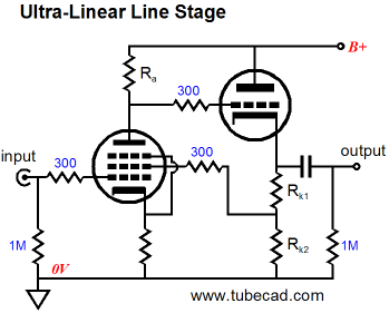
Ultra-Linear Cascode Plus
The name "Cascode" is said to be a contraction of "CASCading triodes with the gain of a pentode and the low-noise of a triODE." I have also seen it described, however, as a contraction of "CASCading triodes having similar characteristics to a pentODE."
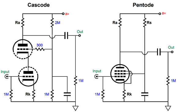
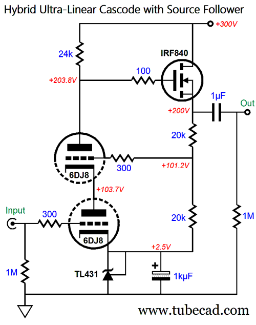
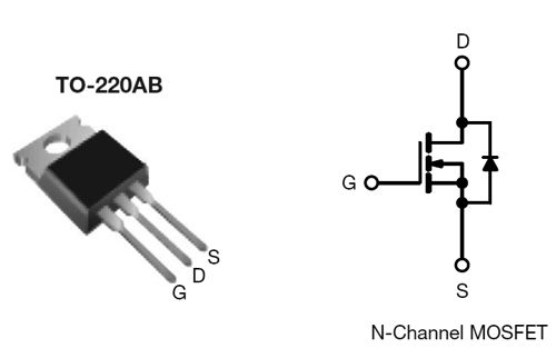
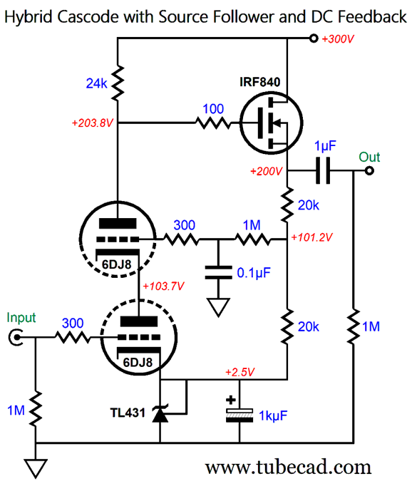
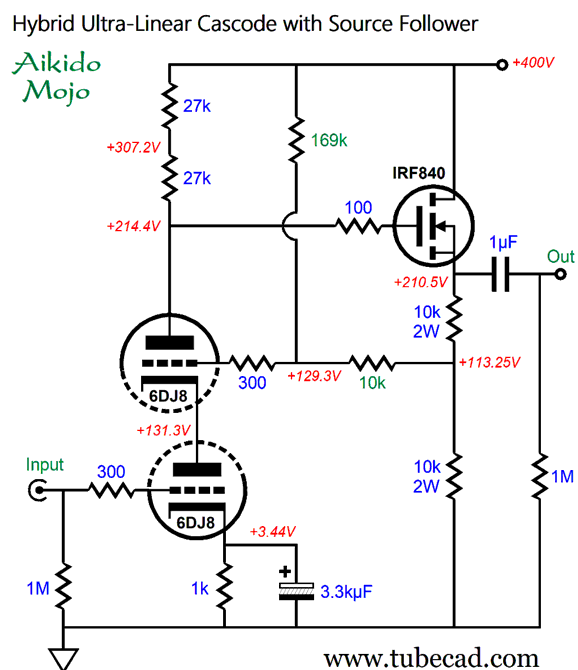
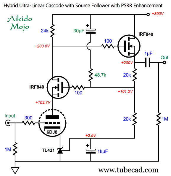
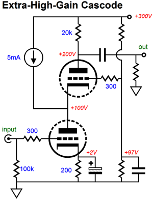
Since the cascode topology is similar to a pentode, adding an ultra-linear flavor is easy enough. Here is a hybrid example that uses a high-voltage MOSFET as a source follower.
The IRF840A is still made by Vishay and it is a 500V/8A/125W N-channel MOSFET in the To-220 package. The source follower uses two source resistors in series and draws only 5mA, so no heatsink is required for the MOSFET (but I would use a small one anyway if for no other reason than to somewhat shield the high voltage present on its metal tab).
The top 6DJ8 triode's grid sees 101.2Vdc at idle but sees 50% of the AC output voltage swing, which creates the ultra-linear effect that lowers both the gain and the distortion. If we do not want the ultra-linear enhancement, we can still use two source resistors to establish only a DC negative feedback loop.
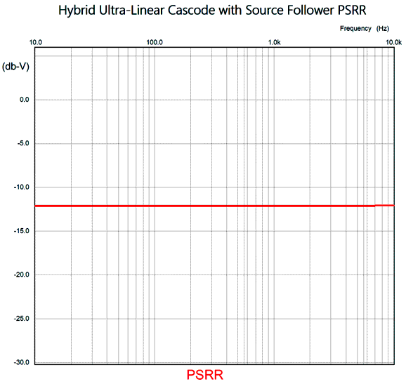
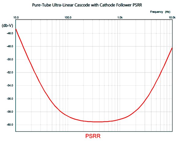
The 0.1µF capacitor shunts the AC signal above 2Hz to ground, but 100% of the DC voltage remains. Of course, the amount of gain from the top triode's grid is small, so the DC negative feedback is relatively weak; still, it cannot hurt. In addition, absent the ultra-linear effect, the gain climbs from 1:50 to 1:150, but at the cost of much higher distortion and a lower potential output voltage swing. Of course, with a microphone preamp, we do not need a high output voltage swing; but we do need it when driving an output tube in a single-ended power amplifier. Why? The ultra-linear effect makes for a much larger potential output voltage swing by dynamically varying the plate voltage on the bottom triode. In addition, the PSRR is far worse with the textbook, non-ultra-linear cascode, the textbook version being only -2dB in this example, whereas the ultra-linear version drops this figure down to -12dB, which is a huge improvement but still not that great.
Let's add some Aikido mojo to this DC-feedback cascode circuit.
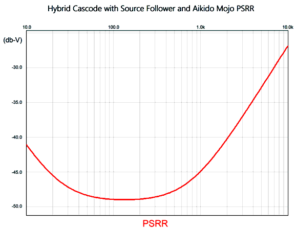
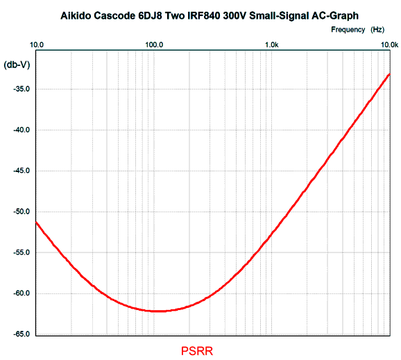
The shunting capacitor has been vastly increased in value, and the three Aikido mojo resistors result in a PSRR of -49dB at 120Hz, the ripple frequency in North America. The gain remains the same, as does the relatively high distortion.
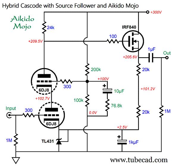
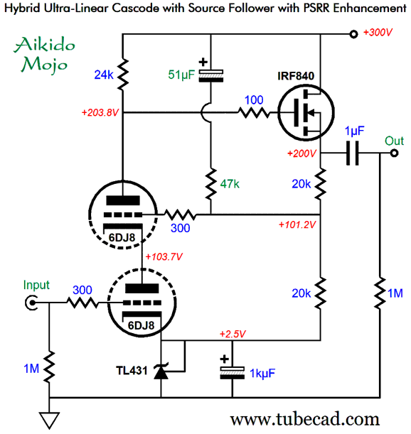
Okay, let's return to the ultra-linear version of the cascode, but with some added Aikido mojo.
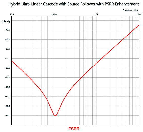
The 51µF capacitor and the 47k Aikido-mojo parts create a crazy deep power-supply noise null of -85dB at 120Hz. Mercy!
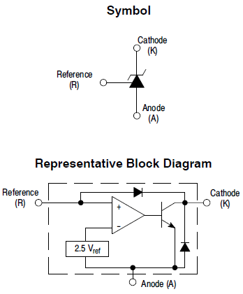
I should explain why a TL431 (or LM431) shunting voltage reference is used.
The TL431 can easily accept the 10mA of current flow and offers a low output impedance. In addition, the shunting 1kµF capacitor should dispel any worries about its influence on the sound. Of course, we could use a cathode resistor instead. In fact, here is a version with a cathode resistor and a higher B+ voltage that is intended to drive an output tube in a single-ended power amplifier.
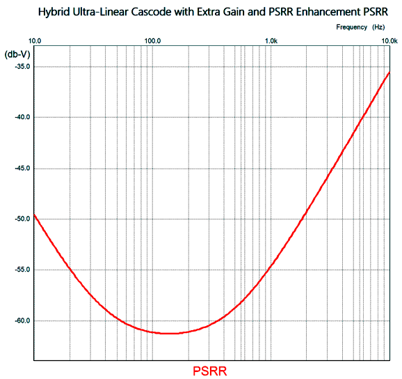
Note that only a 169k resistor is used to attach to the B+ voltage. The PSRR is not as good as in the previous design example, but it is still exceptionally fine for a cascode circuit. To be down -60dB means that only 1/1000th of the power-supply ripple leaks into the output signal.
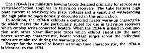
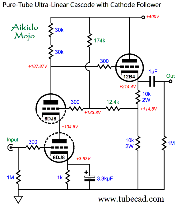
If the cathode-resistor shunting capacitor were larger in value, the null would extend lower in frequency. The gain comes in at 1:55 and the output can easily swing over 100Vpk of output voltage, which should be more than enough for a 300B output tube. No doubt some are thinking: "That's great, John, but why use a MOSFET when we could use another triode?" The problem with using a cathode follower in place of the source follower is that the cathode follower's cathode will be over 200 volts above ground potential, which makes using a single heater power supply unlikely. The workaround would be to give the cathode follower triode its own floating heater power supply that is referenced to the cathode, not ground. Another workaround would be to use a 12B4 single triode in the cathode-follower position. The 12B4, the GE tube manual informs us is:
It can withstand a 550V plate voltage and its dissipation limit is 5.5W. In addition, it is designed to work with a heater -200V relative to its cathode. We could split the cascode's bottom triode's plate voltage (131Vdc) and reference its heater power-supply voltage to 65Vdc, which would create about a 150V heater-to-cathode differential. The floating heater power supply could beas little as a single 6.2Vac heater winding, which could also power the output tube's heater, assuming cathode bias. An added feature to the 12B4 is that it is dirt cheap, even though it is only available NOS; moreover, it offers a center-tapped heater element, so it can be used with either 6.3V or 12.6V heater power-supply voltages.
Missing is my signature protection diode that spans from the 12B4's cathode to the top 6DJ8 triode's plate. (We do not want the 12B4's grid to be 400V more positive than its cathode at startup, when the cathode is cold and not yet conducting. The circuit's gain comes in at 1:55. The PSRR isn't too shabby either.
Once again, this is amazingly good for a cascode circuit, which usually offers only -2dB of PSRR. Of course, we could tilt the ratio more towards solid-state.
The gain pretty much remains unchanged, but some slight tweaking of the Aikido-mojo part values was needed to get the best PSRR figure.
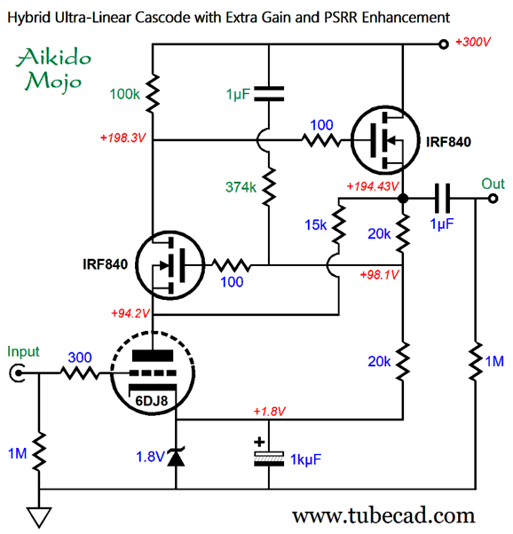
With this setup, only one 6DJ8 would be needed for a stereo microphone preamp or stereo frontend for a single-ended power amplifier. Okay, I will present only one more circuit variation. This time, we see a cascode with an amazingly low-valued load resistor.
Note the 15k resistor. This resistor supplies current to the triode so that less current can flow through the 100k collector resistor. Here is what is usually done to squeeze out more gain from a cascode.
Here is what I said about this cascode variation back in post 303:
In this last hybrid design, the triode draws 7.7mA, the MOSFET atop it draws only 1mA; the 15 resistor leaks 6.7mA of current to the bottom triode. The result is that the gain rises to 1:75 (+37.5dB). With the addition of the Aikido-mojo parts, the PSRR increases to better than 60dB at 100Hz.
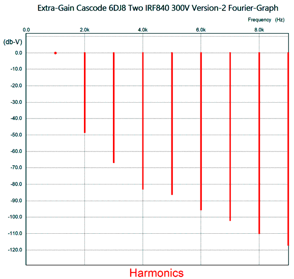
With 1V at 1kHz of input signal, the output voltage swing is 75Vpk and the distortion is surprisingly low for such huge an output swing.
Weirdly enough, we can have it all—high gain, low distortion, and great PSRR. Okay, in spite of that last sentence, I must warn you that this last variation often requires some hands-on tweaking of the current-dripping resistor's value (15k in the schematic), as we want to see a 100V voltage drop across the 100k load resistor.
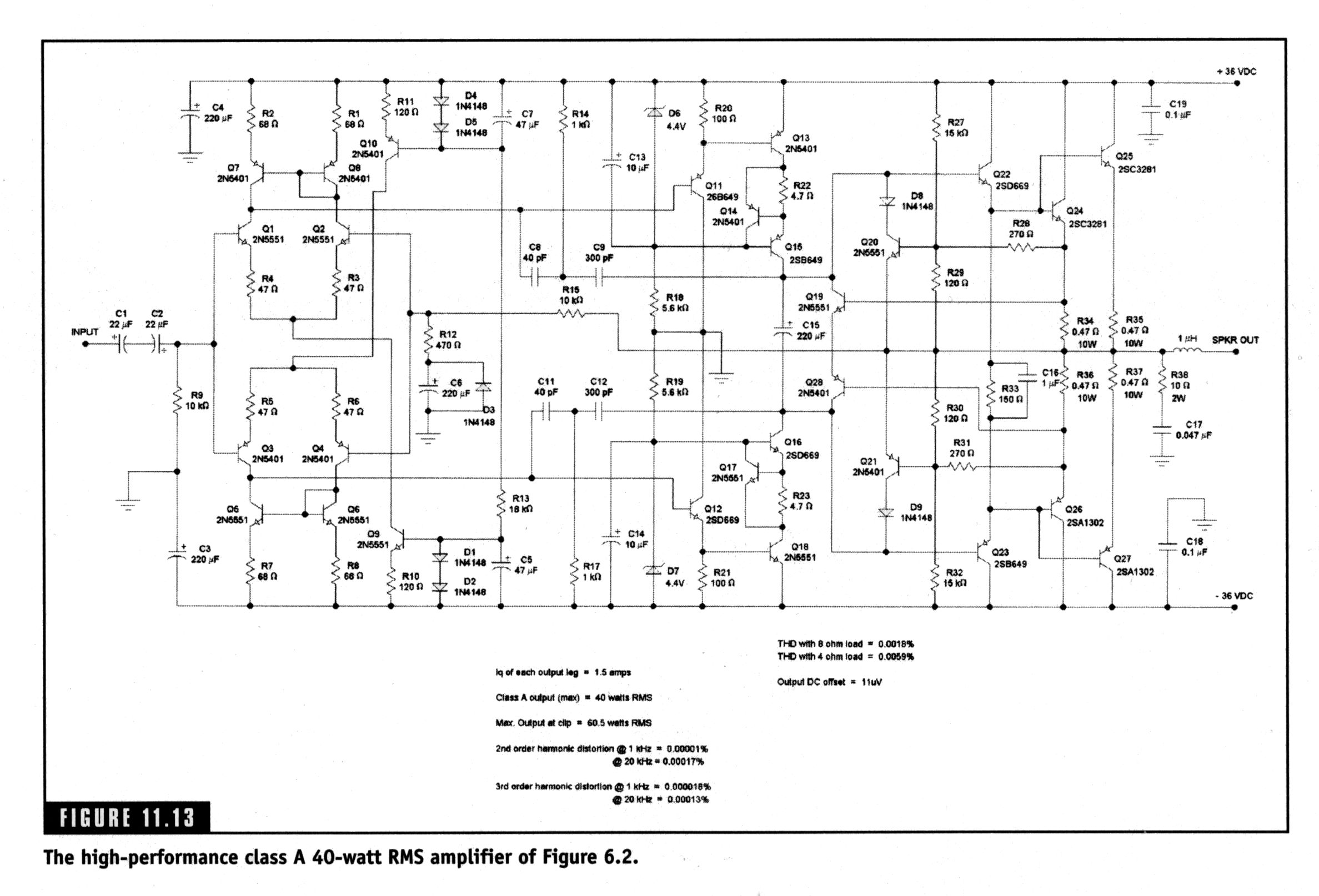
Class-A Auto-Bias It was in the schematic's second appearance in chapter eleven where I came across his observation that the only thing he disliked about his class-A amplifier design was an inherent limitation of the class-A output stage. In his own words:
Since class-A operation is deemed the gold standard for low distortion amplification, I was surprised by his comment. Just what was that inherent limitation due to the class-A output stage's high idle current other than excess heat, huge heatsinks, massive power transformers, and high cost? Why is there a transconductance loss in the output stage due to the high Iq? After examining his schematic, I believe that I know what troubled Slone.
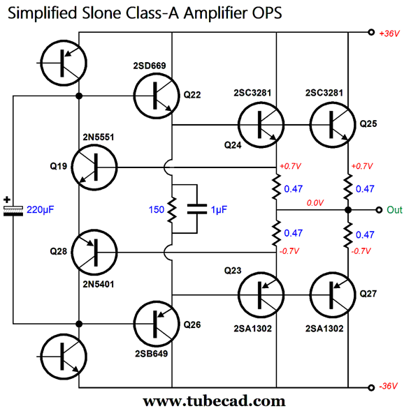
Okay, many a head just exploded, so here is a simplified version that reveals the auto-bias portion of the amplifier, leaving out the symmetrical input stage and complementary cascoded VAS and the two-pole capacitor-compensation network and SOAR current-limiting circuitry.
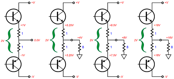
This class-A amplifier output stage employs an auto-bias technique to set the idle current through the output transistors. In other words, no bias-trim potentiometer and no heat-sensing transistor are needed. How so? The voltage drop across the output transistors emitter resistors (R34 & R36) is monitored by transistors (Q19 and Q28) that strive to see a fixed voltage drop equal to their combined base-to-emitter (Vbe) voltage drops. If the voltage drop across the emitter resistors is too low, the collector voltages climb, thereby causing the output transistors to increase their conduction. If the voltage drop grows too high, the collector voltages collapse, thereby decreasing the idle current. Super simple DC negative feedback, in other words. The capacitor (C15) shunting the collectors smoothes things out and provides a low-impedance AC short across the monitoring transistors. The only thing that separates a class-A amplifier from a class-B amplifier, other than weight, cost, and low distortion, is the high idle current flow. A push-pull class-A output stage must idle at least half the maximum expected peak output current swing. This is usually done by taking just the positive bipolar power-supply-rail voltage and dividing it by 8 ohms. For example, with +/-20Vdc rails, we divide 20V by 8 ohms and get 1.5A as the required minimum idle current. Of course, we never actually get 20V of peak output voltage swing from a +/-20Vdc bipolar power supply due to input stage and VAS stage voltage overhead, so we might expect to actually achieve a clean 16V of peak output voltage swing. Now, 16Vpk implies 2A of peak current swing; therefore, we could get away with only 1A of idle current. (I would settle on 1.2A as the target idle current, since few putatively 8-ohm loudspeakers never dip below 8-ohms at some frequencies.) If the power amplifier is operating in strict push-pull class-A mode, the total voltage drop across the pair of emitter resistors should remain constant, from idle to full output power. The following example uses 1-ohm emitter resistors and an idle current of 1A to illustrate the voltage relationships while delivering a varying amount of voltage to an 8-ohm load.
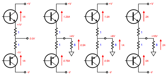
With an idle-current flow of 1 ampere, the maximum class-A output-current swing is 2Apk, which implies 16W of power into the 8-ohm load. This range of -2Apk to +2Apk is the window of class-A amplifier operation, beyond which the output stage moves out of class-A into class-AB operation. Note that in all the four output voltage swings (0V, 4V, 8V, 16V), the voltage differential across the two emitter resistors is equal, i.e. 2Vdc. Let's now look at the current relationships.
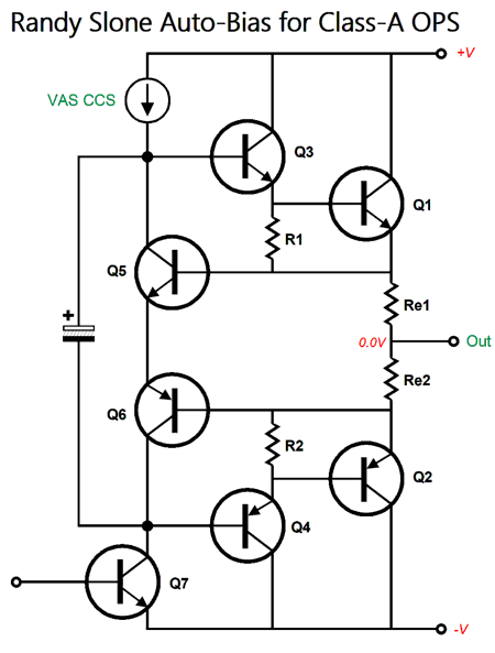
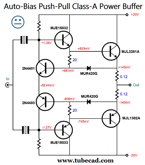
Note the external load sees the delta (the difference) between the top and bottom output transistors; for example, with 8Vpk and 1Apk into the 8-ohm load, the top output transistor draws 1.5Apk, while the bottom transistor draws 0.5Apk, the difference being equal to 1.5A - 0.5A or 1A. Next, we see an even simpler example of the Slone class-A auto-bias scheme from page 153 of Designing High-Power Audio Amplifier Construction Manual.
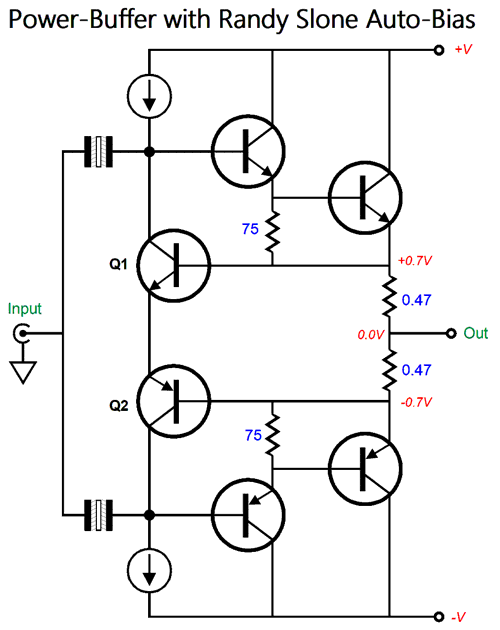
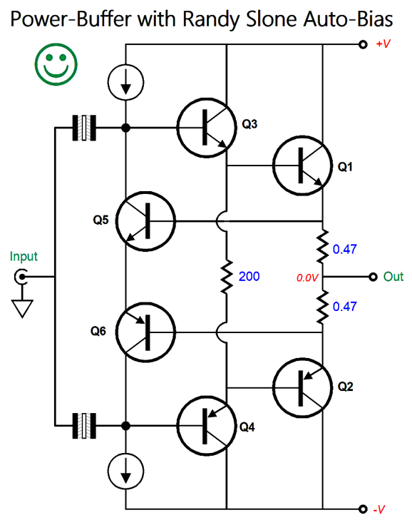
Transistors Q5 and Q6 monitor the voltage drop across the emitter resistors and set the idle current by varying the DC voltages present on the bases of transistors Q3 and Q4. Transistors Q3 and Q1 form a Darlington pair, as do transistors Q4 and Q2. We can easily create a power unity-gain class-A buffer based on this topology.
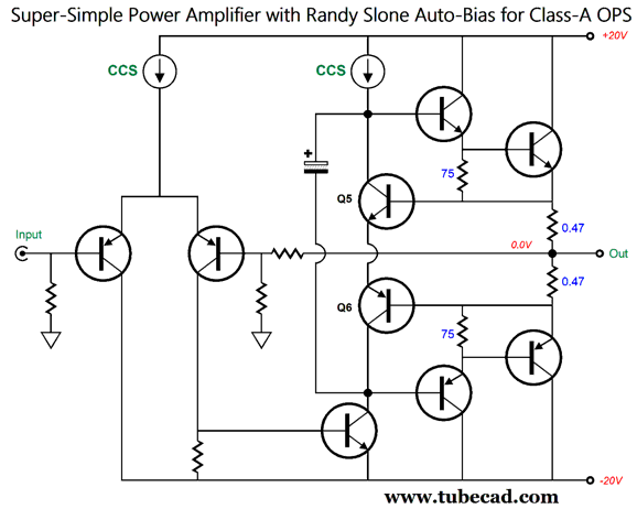
The two non-polarized electrolytic capacitors AC couple the input signal to the emitter-follower output stage. (Actually getting the output to center at 0V will require some more work.) We can easily make a complete power amplifier from the topology.
No more coupling capacitors and only few more parts were needed. It is essential that for the auto-biasing to work that the transistors Q5 and Q6 are not mountedonthe same heatsink as the output transistors; indeed, they should be located away from heat-producing parts. The +/-20Vdc power-supply rails should be enough to allow 16W of power output into an 8-ohm loudspeaker. Of course, we could get fancier.
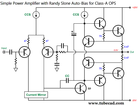
The input stage transistors both get emitter resistors and work into a current mirror—both of which increase linearity. The input coupling capacitor prevents the amplification of any DC offset present on the input signal. The negative feedback loop resistors get a high-frequency-limiting capacitor and low-frequency-cutoff terminating capacitor that allows the amplifier full DC open-loop gain to fuel the negative feedback that will eliminate a DC offset at the output. The dominant-pole capacitor CC limits the voltage-amplification stage (VAS) gain at high frequencies which helps ensure stability (when the global negative feedback loop is attached) and injects high-frequency local negative feedback to the VAS. Now, let's return to a unity-gain buffer design, but with my modification that restores the output stage transconductance.
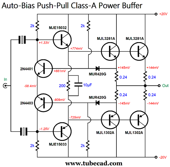
The two MUR420G diodes function as voltage displacers or voltage references of sorts. They allow us to use much lower in value emitter resistors. Indeed, the 0.12-ohm resistors are about one-fourth the value that Slone used in his design (0.47 ohms); thus, much more of the output transistor transconductance is preserved. In other words, the higher the emitter resistor value, the less effective transconductance the output transistors can realize. Imagine an output transistor with a transconductance of 1,000A per increase of 1 volt of base voltage. Now, imagine this same transistor with a 1-ohm emitter resistor that terminates into ground. What is the transistor's effective transconductance now? Only 1A/V or 1 seimen (symbol: S), which is the unit of electric conductance , electric susceptance , and electric admittance in the International System of Units (SI). If the emitter resistor values were 10 ohms, then we would effectively get a transconductance of only 100mA/V. Why the non-yet-happy face? In SPICE simulations, the auto-biasing was not as temperature-independent as I would like. An alternative arrangement of the basic auto-bias topology is the following.
This is the arrangement Slone used in his 40W class-A amplifier. Here transistors Q3 and Q4 no longer deliver any current into the load. Let's use this arrangement within the unity-gain power buffer with diodes and and double up on the output transistors.
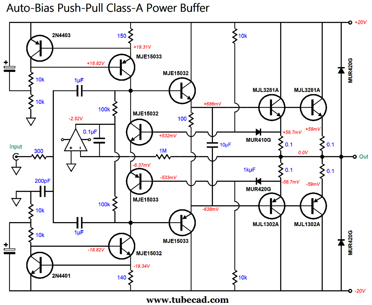
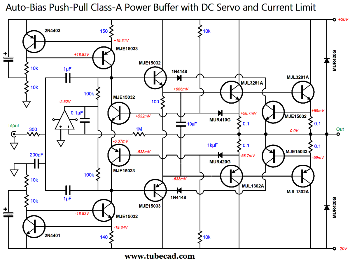
The output stage draws the same amount of idle current as before (1.2A), but each output transistor dissipates half as much heat as before. The output stage effective transconductance remains the same as before, in spite of the 0.24-ohm emitter resistors, as the halving of the transconductance of each output transistor effectively has been cancelled by doubling the number of output transistors. In other words, 2X/2 still equals X. The buffer's input impedance is around 800 ohms, which will require a robust line-stage amplifier to drive. (Remember, this is a unity-gain power buffer, so all the voltage amplification must come from the line-stage amplifier.) If we replace the 2k collector resistors with constant-current sources and add a DC servo, the input impedance will rise dramatically. Here is one possible design:
The relatively low bipolar power-supply-rail voltages allow us to easily use an OpAmp. The two diodes that bridge the output to the bipolar power supply rails are there as "catch" diodes that limit the maximum voltage spikes due to inductive kickbacks from the loudspeaker and its passive crossover. The non-polarized electrolytic capacitor input coupling capacitors have been replaced by much lower in value film or PIO capacitors. The small TO-92 bias-setting transistors have been replaced with TO-220 types, whose lower Vbe voltage allows us to use even lower-in-value emitter resistors. In SPICE simulations, the auto-biasing worked handsomely, as a 100-degree (C) increase in temperature resulted in only the most modest increase in idle current, i.e. 11mA, which is truly small, as the total output stage idle current was 1.17A.
On the other hand, if the 2N4401 and 2N4403 constant-current-source transistors are located next to the output transistor's heatsink, a negative current slope occurs, which could protect the power buffer from meltdowns. In other words, the idle current falls with excess heat. Speaking of protection circuitry. The auto-bias arrangement offers some protection from a shorted output, as the bias-setting transistors enforce a strict DC limit to the current flow through the output transistors—but only slowly due to the shunting coupling capacitors, alas. For example, with a shorted output and a 16Vpk input signal at 10Hz, the maximum output current tops out at 5Ak; but with the same signal amplitude at 100Hz, the maximum current peaks at 60A. Not good when the output is shorted to ground. But 4A peak is good, when the output drives a 4-ohm loudspeaker, as the output stage can shift into class-AB operation on music peaks. (This 16W power buffer can only deliver 8W in strict class-A operation with a 4-ohm load, but can deliver 32W of class-AB output into 4 ohms.) In general, I dislike active output stage protection circuitry that clamps the signal internally, rather than disconnecting the loudspeaker from the output with a relay. Why? It can make for harsh clipping when activated and the loudspeaker and output stage are not really in trouble. For example, some high-end loudspeakers hold truly botched passive crossovers, which can result in steep declines in impedance over a narrow band of frequencies. One famous high-end loudspeaker was equally famous for its drop to 1 ohms at some midrange frequency. Unless one uses, however, a signal generator set to the midrange frequency and ran the buffer at full output into that famous loudspeaker, there's no real problem with music reproduction. Nonetheless, here is one possible workaround.
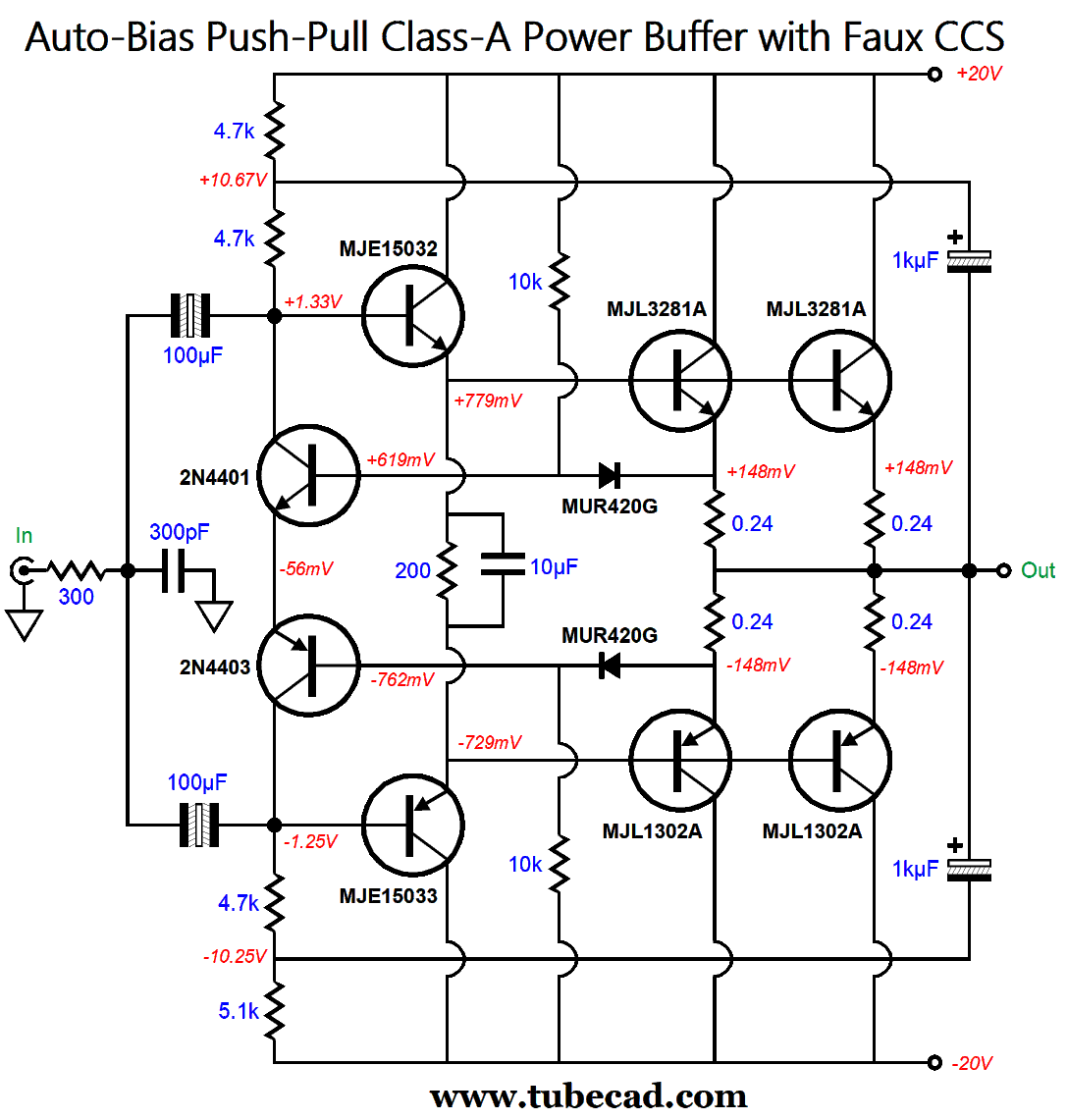
The added two voltage-clamping transistors limit the maximum output stage current flow to about 12A, which should be enough to protect the output transistors until the fuses blow. Sadly, transistors are often referred to as fuse-protection devices. In contrast, MOSFETs are far more robust and seldom, if ever, cause the reverse-domino cascade of destruction of the driver stage that transistors are famous for doing. So, why not use output MOSFET instead? We could, but at the cost of less output power, as the MOSFET's much higher turn-on gate-to-source voltage necessarily limits the maximum output voltage swing in this circuit with wee bipolar power-supply-rail voltages. (The workaround would be to run a secondary bipolar power supply at a higher voltage to power everything other than the output stage.) The more I think about it, the more I would prefer something simpler. This got me thinking about using a faux (i.e. fake) constant-current source.
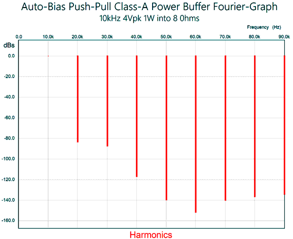
The added 1kµF bootstrap capacitors and the lighter input-stage current flow results in an input impedance of about 30k, which most tube-based line-stage amplifiers should easily be able to drive to 16Vpk, as only half a milliamp of peak current is needed. With one watt of output into an 8-ohm load at 10kHz, the distortion in SPICE simulations was below 0.01% and beautifully single-ended in harmonic structure.
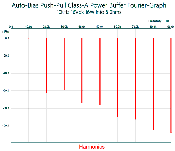
At full output, i.e. 16W, the THD rises a tad over 0.1%, but its cascade of harmonics still looks good.
The distortion was a bit lower without the input RFI filter, but filtering away ultra-high frequencies above 1MHz is always a good idea. Do not forget: no negative feedback loop was employed in this power buffer. Now, just imagine a tube-based linestage amplifier that can put out a 16Vpk output signal.
Music Recommendation: Dvorak While on the topic of Dvorak, if you do not know his tome poems, you should. Just lovely music. Sir Simon Rattle conducting one of the finest orchestras is about as good as it gets.
Both albums are available at Qobuz and Amazon Music Unlimited streaming service in high-res, 24-bit and 44.1kHz .
//JRB
Did you enjoy my post? Do you want to see me make it to post 1,000? If so, think about supporting me at Patreon. The more support I receive, the more I can post.
User Guides for GlassWare Software
For those of you who still have old computers running Windows XP (32-bit) or any other Windows 32-bit OS, I have setup the download availability of my old old standards: Tube CAD, SE Amp CAD, and Audio Gadgets. The downloads are at the GlassWare-Yahoo store and the price is only $9.95 for each program. http://glass-ware.stores.yahoo.net/adsoffromgla.html So many have asked that I had to do it. WARNING: THESE THREE PROGRAMS WILL NOT RUN UNDER VISTA 64-Bit or WINDOWS 7, 8, and 10 if the OS is not 32-bit or if it is a 64-bit OS. I do plan on remaking all of these programs into 64-bit versions, but it will be a huge ordeal, as programming requires vast chunks of noise-free time, something very rare with children running about. Ideally, I would love to come out with versions that run on iPads and Android-OS tablets.
|
I know that some readers wish to avoid Patreon, so here is a PayPal button instead. Thanks.
John Broskie
John Gives
Special Thanks to the Special 80 To all my patrons, all 80 of them, thank you all again. I want to especially thank
All of your support makes a big difference. I would love to arrive at the point where creating my posts was my top priority of the day, not something that I have to steal time from other obligations to do. The more support I get, the higher up these posts move up in deserving attention.
If you have been reading my posts, you know that my lifetime goal is reaching post number one thousand. I have 432 more to go. My second goal was to gather 1,000 patrons. Well, that no longer seems possible to me, so I will shoot for a mighty 100 instead. Thus, I have just 20 patrons to go. Help me get there. Thanks.
Support the Tube CAD Journal & get an extremely powerful push-pull tube-amplifier simulator for TCJ Push-Pull Calculator
TCJ PPC Version 2 Improvements Rebuilt simulation engine *User definable
Download or CD ROM For more information, please visit our Web site : To purchase, please visit our Yahoo Store: |
|||


| www.tubecad.com Copyright © 1999-2021 GlassWare All Rights Reserved |