| John Broskie's Guide to Tube Circuit Analysis & Design |
14 September 2022 Post Number 566
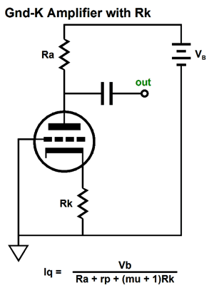
Exploiting the Cathode Voltage
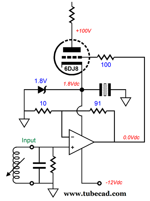
A grounded-cathode amplifier idle current can be set in three different ways. Usually, we use a cathode resistor or a constant-current source or zener in place of a cathode resistor. We could use fixed bias, wherein we apply a negative bias voltage to the grid, while the cathode is grounded. Or, we could replace the plate resistor with a constant-current source. When using a cathode resistor to set the idle current, the resistor is often bypassed by a large-valued capacitor. Well in the setup with a bypassed cathode resistor, the cathode voltage relative to ground can be exploited. Here is an example: many low-noise OpAmps, such as the AD797, can be run off just a +/-5Vdc bipolar power supply. Compared to any vacuum tube, the AD797 is dead quiet, which makes its suitable candidate for an MC pre-preamp in an otherwise all-tube phono stage. We need the OpAmp to boost the MC cartridge's wee output signal to a level where the tubes can take over, which usually is about 20dB or 1:10 amount of extra gain. Of course, the assumption here is that the triode draws enough current to support powering an OpAmp. in other words, a 12AX7 drawing 1mA is not going to work, but a 12AU7 drawing 5mA might. The following circuit uses a negative power-supply rail of -12Vdc to power the OpAmp and heat two tube heater elements in series, while the left triode's cathode voltage creates the small 1.8Vdc positive-rail voltage for the OpAmp.
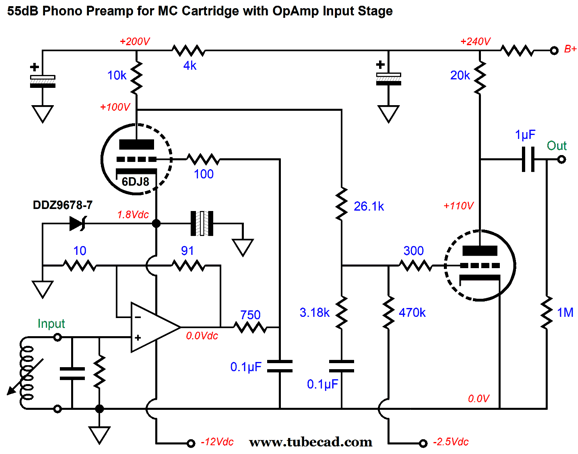
Now, let's plug it into place in a high-gain phono preamp.
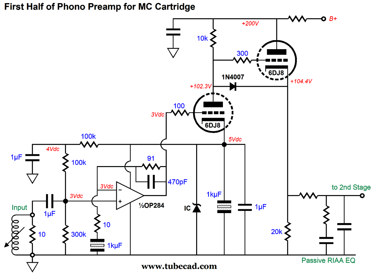
The AD797's gain is set by its two negative feedback resistors, 10 and 91 ohms, which establish a gain of roughly +20dB. The OpAmp then drives a 2122Hz (75µs) low-pass filter (i.e. the 750-ohm resistor and 0.1µF capacitor) that accomplishes the second half of the RIAA equalization. The left 6DJ8 triode DC couples to the filter's output and adds further gain, before driving the passive second half of the RIAA equalization network that creates the 20dB boost from 50Hz to 500Hz. The right 6DJ8 triode contributes more gain, bringing the final total to 55dB. Only one 6DJ8 is needed per channel and the AD797 ensures low noise. What if you are running a high-output MC or MM cartridge? Well, the topology can be retained, but a different tube would be used to bring down the gain, for example a 6SN7 or 12BH7. In fact, these tubes will develop a higher cathode voltage for the same 10mA of idle current flow, which will be appreciated by the OpAmp, as it will have to deliver larger output voltage swings. What if you do not have a negative power-supply rail to tap into? Well, they make low-noise OpAmps for use with 5Vdc power supplies, such as the OP284. (No doubt, there must be newer, better OpAmps, but I have failed to keep up with OpAmp development.) Here is an example design that uses the cathode current flow to charge up a large-valued capacitor and engage a 5V zener diode or 5V voltage reference IC.
(The IC voltage reference and its bypass capacitors can be shared by both channels.) The OpAmp delivers a gain of 1:10 (+20dB), but we could easily increase or decrease the amount of gain without altering the bias voltage for the triode above the circuit. The Triode on the left is a simple grounded-cathode amplifier, which is followed by a cathode follower, which in turn drives the passive RIAA equalization network. So what's not to like about this design? Capacitors, far too many capacitors. A workaround exists, however, that eliminates the need for a fistful of capacitors: the differential input configuration.
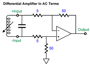
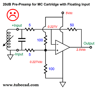
A moving-coil phono cartridge consists of a coil of wire suspended in a strong magnetic field. As the needle vibrates, the coil vibrates, thereby causing the generation of a small AC current flow. The coil is free floating, i.e. not tied to ground. It does get grounded, but inside the phono preamp. In the circuit shown above, the coil is not grounded and sees no net DC differential voltage but does see a load resistance of 10 ohms. The OpAmp delivers a gain of 1:10 (+20dB). To see how this is possible, here is the AC equivalent circuit.
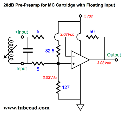
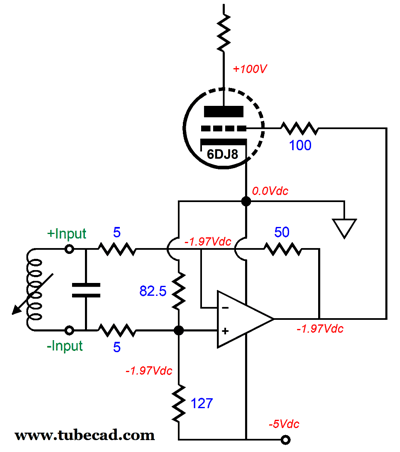
In theory, the 5Vdc termination is the AC equivalent of ground, so the two 100-ohm resistors are effectively in parallel. The only problem we face is that the circuit evenly splits the 5Vdc at its output, but the 6DJ8 would prefer something closer to -2Vdc at its grid. Here is the sneaky workaround.
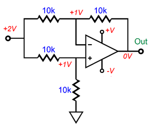
In AC terms, the circuit is the same as the previous one, as 82.5 ohms in parallel with 127 ohms makes 50 ohms. By the way, the great advantage afforded by differential amplifiers is the ability to ignore common-mode signals, which is usually noise. In other words, the amplifier only amplifies differences. If +1 and -1 go in, out comes +2; if, on the other hand, if +2 and +2 go in, out comes 0V. Since there was no difference between the two, they were ignored entirely.
To make this setup work requires tightly matched resistors; using 0.1% types is a good start. In addition, this setup can run into a big snag, sadly. Some cartridges, tonearms, and turntables ground the cartridge's coils for us; a super bad idea, but that does not stop some from doing so anyway. (There is a good reason that turntables come with a ground wire.)
Note the two ground connections. Asides from potential hum issues, the OpAmp sees too low a DC voltage at its two inputs. (Some opAmps might work in this circuit, depending on their input circuit. Always read the data-sheet.) By the way, we could float the cartridge coil negatively.
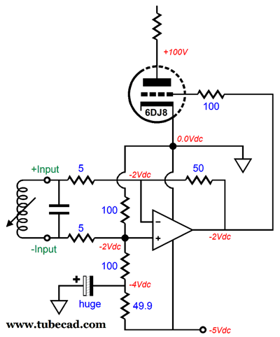
Note that the 6DJ8's cathode terminates directly into ground, so no issues of bypass capacitor sonic ills can arise. Of course, we will need a negative power-supply rail, but it could also be used to power the heater elements, with further cascading 5V regulation for the OpAmp.
This variation uses a large-valued capacitor to filter the DC at the input even further. If you are wondering why I specified 5-ohm and 50-ohm resistors when they are not made, the answer is that we would parallel up two 1-ohm and two 100-ohm resistors. There will be more on this topic next time.
Thanks to those who have donated to my efforts. Your support makes a difference.
Bi-Amping a Bi-Wire Loudspeaker
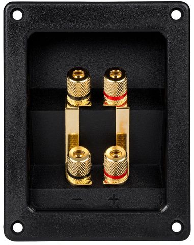
If you choose not to bi-wire, you simply use two short bridging wires to tie the positive terminals together and the negative terminals together.
Well, what if you are more ambitious, wanting to use two power amplifiers per speaker, how would that work? The easy way is to simply buy another identical stereo power amplifier and use one stereo amplifier per loudspeaker, with each amplifier delivering the same signal to the bi-wire terminals. This certainly works, but it buys us little (if any) real improvements. Why not? Both amplifiers must deliver full bandwidth and both will clip at the same time.
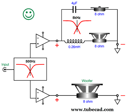
In contrast, in an optimally configured bi-amp system, one with an external active crossover, each amplifier will only deliver half of the bandwidth. Thus, we can expect the woofer amplifier to clip far sooner than the tweeter amplifier, which might not ever clip, as most the energy is in the low frequencies of a recording, with a few exceptions, such as some purely electronic music, which is not limited by actual musical instruments (or good taste).
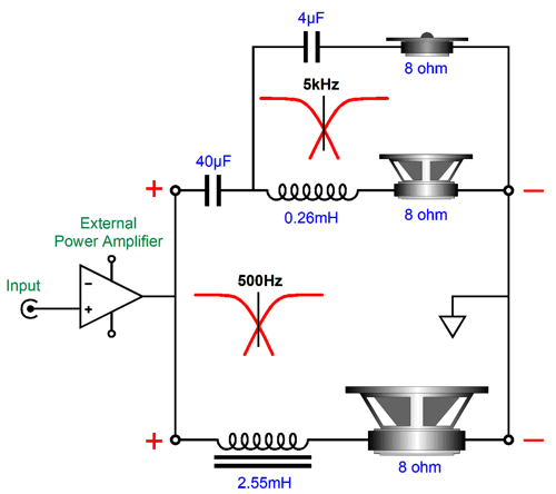
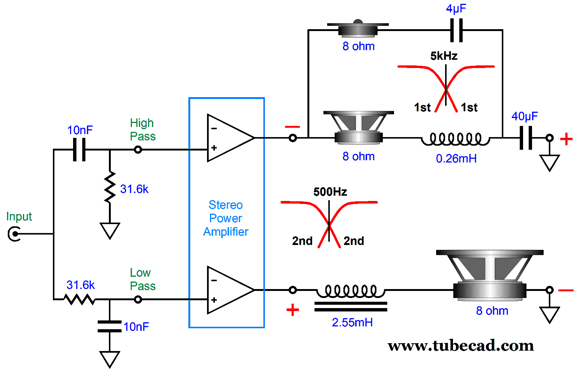
We cannot add an external active crossover before the two power amplifiers with the loudspeaker that offers bi-wiring, as the internal passive crossover assumes a full bandwidth input signal. Some have fudged this arrangement by using different and overlapping crossover frequencies on the external active crossover than what is used in the internal passive crossover. For example, a bi-wireable loudspeaker might cross over at 500Hz between its woofer and midrange. The external, 1st-order, active crossover would then limit the low output with a low-pass filter set to 2kHz, while the highs output would see a high-pass filter at 125Hz. The hope here is that the two-octave spread away from the 500Hz crossover frequency is sufficient to prevent a lumpy frequency response. It just might be enough, if the loudspeaker holds a 3rd-order or 4th-order passive crossover; otherwise, expect lumps. One workaround would be to open up the loudspeaker and undo the passive crossover, so the woofer connects directly to the bi-wire bottom terminals, with only those parts needed for crossing over the midrange to the tweeter left in place. Now, an external active 500Hz crossover could be used. A huge pain this is, especially if you hope to sell the speakers in the future or if you buy a different, more powerful or more expensive power amplifier, so bi-amping is no longer desirable (or affordable). Well, I thought of another workaround, but it is not a universal one. Let's say that a loudspeaker holds a 1st-order crossover at 500Hz between woofer and midrange. If our an external active 500Hz crossover was also a 1st-order type (which could easily be passive and not active), the two 1st-order 500Hz filters would cascade, thereby creating a 2nd-order Linkwitz-Riley 500hz crossover, with both woofer and midrange down -6dB at 500Hz and both summing to flat.
In order to make this work, however, the phase must be flipped on the high-frequency drivers. The loudspeaker will no longer be phase-flat, but it will probably be able to handle a lot more power.
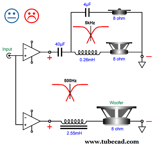
The active high-pass filter is configured in the inverting mode, so there's no need to flip the phase at the bi-wire terminals. If the following passive crossover is used, then the phase must be flipped at the top bi-wire terminals.
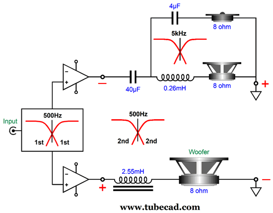
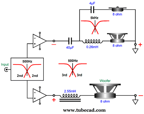
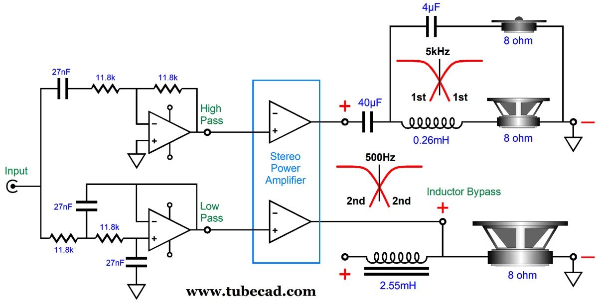
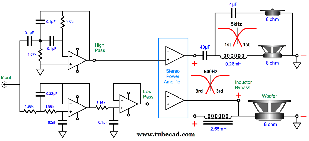
I can imagine a loudspeaker company selling a matching external active 500Hz crossover for their loudspeaker, working on the assumption that the 1st-order would work just fine with high-quality, but low-output power amplifiers, either class-A solid-state or tube-based amplifiers; with high-power amplifiers, however, the bi-amp approach would prove safer for the midrange and tweeter. Well, we can take this workaround one step further or, rather, one step steeper, as we can use a 2nd-order external active 500Hz crossover to create a 3rd-order effective crossover between the woofer and midrange.
Note the needed phase inversion for the top of the speaker's drivers. Of course, we could include the inversion within the active 2nd-order crossover, just as we had with the active 1st-order crossover.
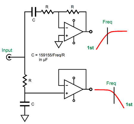
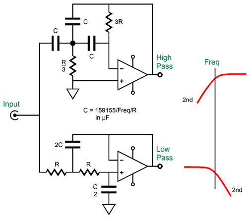
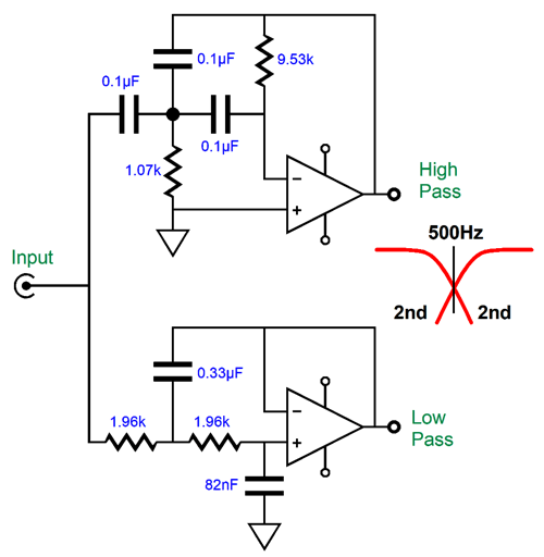
The high-pass filter is configured in the multiple-feedback (MFB) topology, which inverts the signal phase at its output, which is needed with the 3rd-order alignment. The low-pass filter is configured in the famous and ubiquitous Salen-Key topology, which does not invert. Both filters present a Q of 1, which cascades with the internal loudspeaker passive crossover to create a final Q of 0.707, the Butterworth alignment. Here is a design example with the crossover frequency of 500Hz.
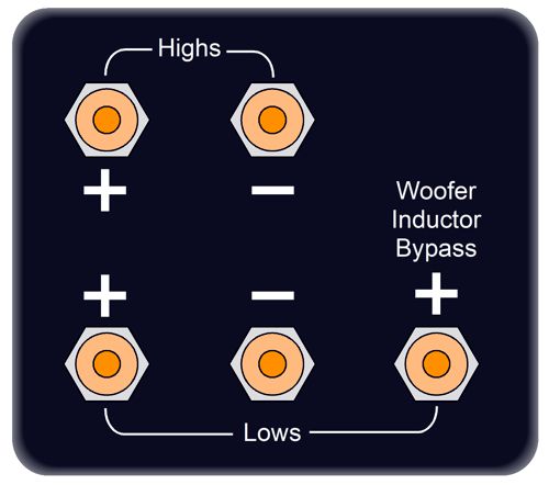
Here is one last crazy idea from me on this topic. In all the examples, the woofer was in series with crossover inductor tuned to the 500Hz crossover frequency. What if we could avoid using the inductor? Why? The quick answer is that inductors disappoint (i.e. suck). How so? They are often made with thin magnet wire that presents a relatively high DCR (DC resistance), which entirely undoes the solid-state power amplifier's damping factor of 1,000. They often are not air-core, but cored with iron or ferrite, which can saturate. They are hum magnets, unless shielded in a potted case. Well, what if the speaker maker added one extra bi-wire terminal on the back of their speakers? This extra terminal would bypass the inductor.
The passive internal speaker crossover needs only an extra wire.
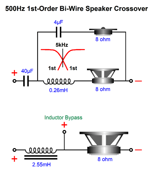
Now, when bi-amping, we would let the external active crossover take the place of the missing inductor. In other words, in the 2nd-order Linkwitz-Riley alignment, the highs amplifier would see a 1st-order 500Hz high-pass filter, while the lows amplifier would see a 2nd-order 500Hz Linkwitz-Riley low-pass filter.
The low-frequency power amplifier now drives the woofer directly. We could do the same with the 3rd-order crossover.
This setup purposely retains the 500Hz high-pass capacitor inside the loudspeaker, as it offers greater protection of the delicate midrange and tweeter. If the high-frequency power amplifier loses its ground connection, it will put out a huge hum signal at 50Hz or 60Hz that can easily toast a midrange or tweeter; but with the internal capacitor in place, the huge hum signal will be attenuated by 20dB, thereby offering much greater safety. In addition, the capacitor will block any DC offset the power amplifier might present.
Music Recommendation: Wicked (Just what does the phrase, "Live in the studio," mean? I have seen it before and it never made any sense to me. Do some musicians perform while dead? Or, does it mean that a small audience attended the recording sesion in the studio?) Amazon Music streaming service offers this album in 24-bit, 96kHz. Well worth hearing.
//JRB
Did you enjoy my post? Do you want to see me make it to post 1,000? If so, think about supporting me at Patreon.
User Guides for GlassWare Software
For those of you who still have old computers running Windows XP (32-bit) or any other Windows 32-bit OS, I have setup the download availability of my old old standards: Tube CAD, SE Amp CAD, and Audio Gadgets. The downloads are at the GlassWare-Yahoo store and the price is only $9.95 for each program. http://glass-ware.stores.yahoo.net/adsoffromgla.html So many have asked that I had to do it. WARNING: THESE THREE PROGRAMS WILL NOT RUN UNDER VISTA 64-Bit or WINDOWS 7, 8, and 10 if the OS is not 32-bit or if it is a 64-bit OS. I do plan on remaking all of these programs into 64-bit versions, but it will be a huge ordeal, as programming requires vast chunks of noise-free time, something very rare with children running about. Ideally, I would love to come out with versions that run on iPads and Android-OS tablets.
|
I know that some readers wish to avoid Patreon, so here is a PayPal button instead. Thanks. John Broskie
John Gives
Special Thanks to the Special 77 To all my patrons, all 77 of them, thank you all again. I want to especially thank
All of your support makes a big difference. I would love to arrive at the point where creating my posts was my top priority of the day, not something that I have to steal time from other obligations to do. The more support I get, the higher up these posts move up in deserving attention.
If you have been reading my posts, you know that my lifetime goal is reaching post number one thousand. I have 436 more to go. My second goal was to gather 1,000 patrons. Well, that no longer seems possible to me, so I will shoot for a mighty 100 instead. Thus, I have just 23 patrons to go. Help me get there. Thanks.
Support the Tube CAD Journal & get an extremely powerful push-pull tube-amplifier simulator for TCJ Push-Pull Calculator
TCJ PPC Version 2 Improvements Rebuilt simulation engine *User definable
Download or CD ROM For more information, please visit our Web site : To purchase, please visit our Yahoo Store: |
|||


| www.tubecad.com Copyright © 1999-2022 GlassWare All Rights Reserved |