| John Broskie's Guide to Tube Circuit Analysis & Design |
12 February 2022 Post Number 553
Powering an Internal Subwoofer
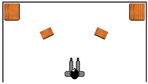
Reproducing deep bass frequencies requires huge woofer cone excursions, which can only muddy the midrange. A simple experiment is to introduce a high-pass filter, say at 100Hz, in front of your power amplifier, but do not add a subwoofer. Play some music with vocals and attend to the articulation of the voice with the filter in place and without, i.e. without deep lows and full bandwidth. Freed from the onerous task of reproducing deep bass, the woofer is better able to render the mid-bass and midrange accurately. The huge problem with adding a subwoofer, however, is getting it to mesh well with the existing loudspeakers. Not an easy task. Most subwoofer setups sound bloated and unnatural. Much like makeup, a subwoofer works best when you cannot tell that it is there. Sadly, many audiophiles want to get their money's worth, good and hard. They paid a lot for their subwoofers, so, damn it, they should really hear them. And we do hear them, as disjointed thunderous thumpers. Beyond a mismatch in sound levels, subwoofers are often not phased correctly relative to the main loudspeakers. Moreover, the subwoofers are often positioned far away from the main speaker, creating time distortion, as the subwoofer's output arrives after (or before) the main speaker's output. I remember seeing and hearing a friend's setup. He owned two huge subwoofers, say easily two-foot large wooden cubes that bracketed his listen chair and which he used as end-tables. In his setup, the subwoofer output arrived much sooner than the main speaker's output, as the main speakers sat in the corners. In addition, his subs played at least 6dB louder than the main speakers. Although the resulting sound was less than perfect, the massage delivered was invigorating.
In contrast, building the subwoofer into the loudspeaker allows the speaker designer to eliminate many variables from consideration, as the subwoofer and woofer's properties are known. In addition, the subwoofer location relative to woofer is fixed. Since class-D amplifiers are so cheap and produce little heat, adding one to the loudspeaker to power the subwoofer is easy enough. What gets complicated is adding the crossover between the subwoofer and the woofer, the hard part being adding the high-pass filter to the woofer driver. Doing so passively requires at least one huge capacitor, which can easily cost more than the class-D amplifier. For example, a 200µF crossover capacitor is needed for a 100Hz crossover frequency with an 8-ohm woofer. A Solen 200µF, 400V polypropylene capacitor, which many would deem an entry-level capacitor, cost about $75. A Duelund 50µF capacitor costs about $750 and four would be needed per loudspeaker; thus, $3,000 per speaker.
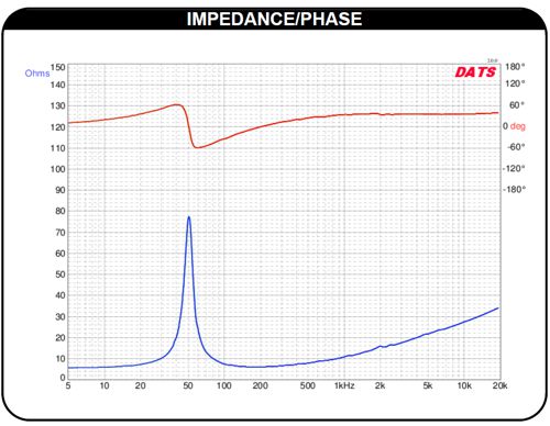
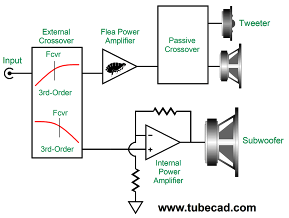
Worse still, there is little expectation that the crossover capacitor would perform as expected due to the woofer's impedance peak at its resonant frequency, where a typical nominally 8-ohm woofer can peak at 80 ohms. The alternative is active filtering. Doing so actively requires placing the high-pass filter in front of the external power amplifier, which requires a far smaller-valued capacitor, say 0.1µF. This setup greatly unloads the external power amplifier and adds extra protection to the midrange and tweeter drivers. But this active arrangement brings a new problem: How does the loudspeaker's internal subwoofer power amplifier get its signal?
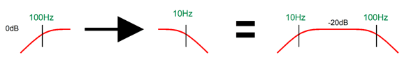
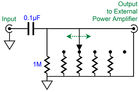
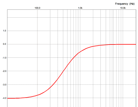
We could run a long length of interconnect from the external crossover box to the loudspeaker, as we see above, but this is a huge hassle. Alternatively, we could use the signal that comes from the external power amplifier and terminates at the speaker terminals as the signal source. The problem now is that this signal is no longer full bandwidth, as the high-pass filter has imposed the sloping decline in low frequencies. In other words, the subwoofer would see the same high-pass filter function, thus no net increase in bass response. The workaround is to restore the missing bass signals by boosting the lows in a countervailing fashion. For example, if a 1st-order high-pass filter tuned to 100Hz were placed in front of the external power amplifier, then we must boost the low frequencies with an upward boosting slope of 6dB per octave, 20dB per decade. In theory, the slope would need to continue infinitely to DC to restore fully the fullrange bandwidth. In practice, we would set a limiting frequency, say 10Hz, which would cease boosting below 10Hz, effectively creating a high-pass 1st-order filter at 10Hz.
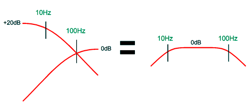
We cascade the output from the 100Hz high-pass filter into a 10Hz low-pass filter. The result is effectively a band-pass filter with cutoff frequencies of 10Hz and 100Hz. We do, however, incur an insertion loss of signal level of -20dB. On the other hand, if we boost the signal leaving the 10Hz high-pass filter by 20dB, the band-pass filter will deliver unity gain (0dB).
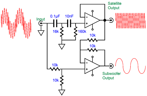
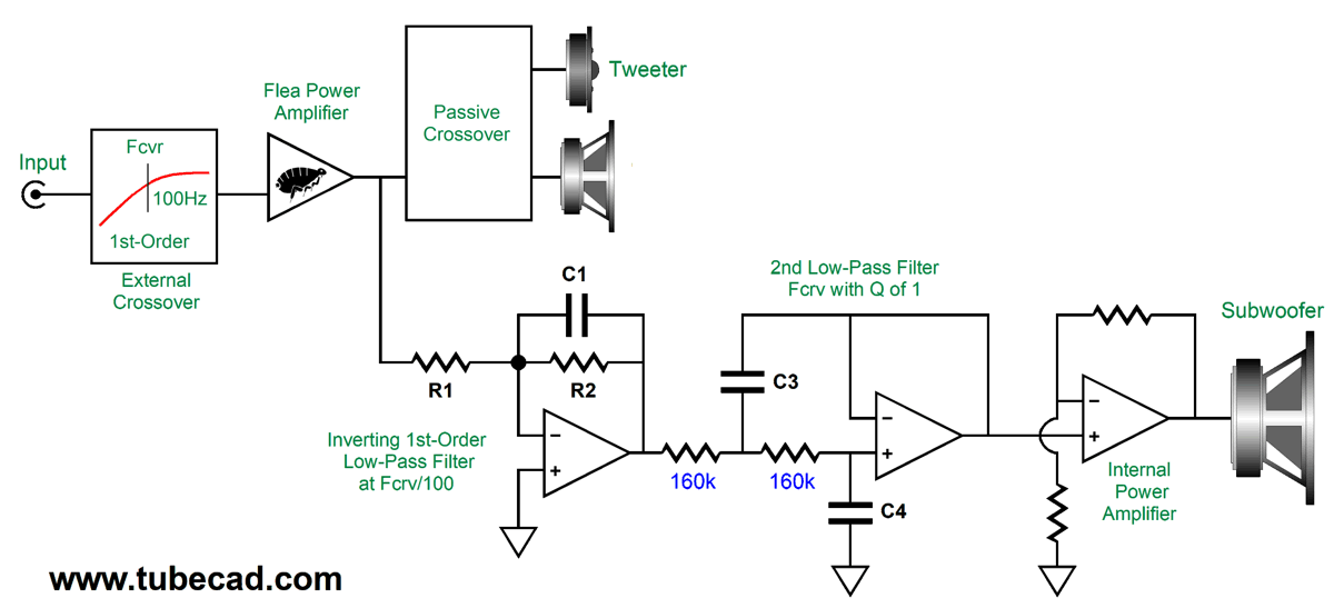
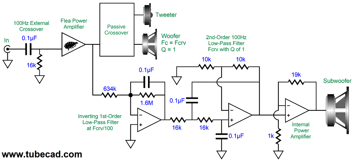
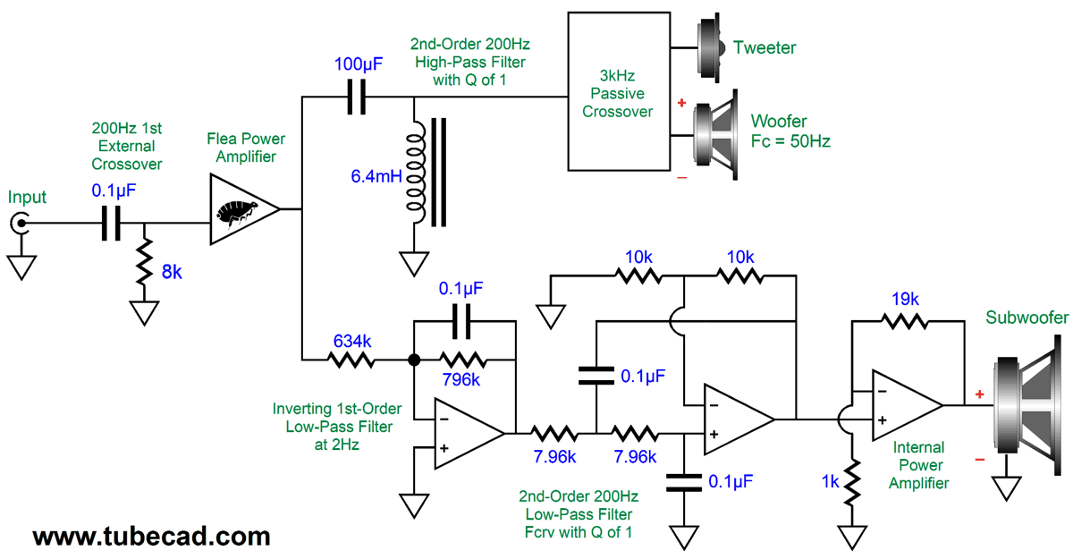
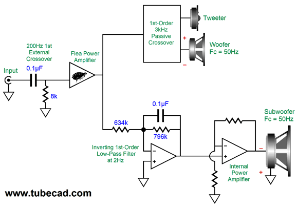
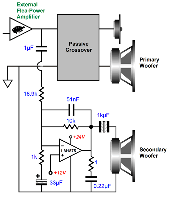
Of course, we can apply the 20dB boost after the low-pass filter just as well. Here is an example of how the internal subwoofer amplifier can get its signal and how a 3rd-order low-pass filter can be imposed upon it.
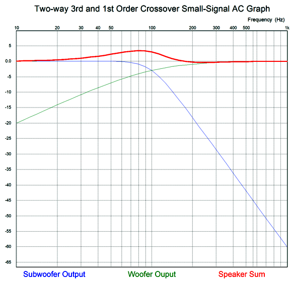
Note that the signal leaving the flea-power amplifier is filtered of deep bass by the external crossover, which unloads the amplifier and the woofer—and tweeter. The inverting amplifier takes this filtered signal and imposes the low-pass filtering on it, so as to restore the missing bass signal. Resistor R2 and capacitor C1 set the low-pass filter frequency by a simple formula: C1 = 159155/R2/Fcrv where C1 is in µF. Resistor R1 sets the gain or attenuation of the signal leaving the inverting amplifier. The next stage is a 2nd-order low-pass filter with a Q of 1. The two low-pass filters in series creates a 3rd-order low-pass filter with a Butterworth alignment (i.e. a Q of 0.707). The result is an asymmetrical crossover, with 1st- and 3rd-order slopes. Many love this arrangement, as it results in a bass hump of +3.4dB; in this example with a crossover frequency of 100Hz, the hump will center at about 80Hz. For many, 80Hz is deep bass and the bump in the bass makes them feel that the subwoofer is doing its job. In other words, many will view the bass bump as a feature, not a bug.
The downside to this workaround is that the low-frequency noise will also be boosted. For example, assuming a 50Hz wall-voltage frequency, if 50Hz hum was down -80dB at the external power amplifier's output, it would be increase by 6dB with a 100Hz crossover frequency, bringing it up to -74dB. If a 2nd-order high-pass filter were used rather than the 1st-order, the boost would be 12dB; 3rd-order, 18dB; and 4th-order, 24dB. The higher the crossover frequency, the greater the hum boost would be. For example, with a crossover frequency of 200Hz, all the hum boosts must be doubled. A 48dB boost of 50Hz hum, with undoing the 4th order high-pass filter, is staggering. Bear in mind that the hum originates in the external power amplifier, which a tube-based design is much more likely to leak hum than a solid-state amplifier due to its much higher amount of negative feedback employed. In contrast, if the signal source, say a CD contains hum, which was introduced during the recording, the hum would be treated the same as music signal and passed along flat. Since the external power amplifier introduces low-frequency noise after the high-pass filtering, however, that noise will be boosted. Poor grounding, for example, can induce hum in any type of power amplifier. Rectifier hum (i.e. ripple), in contrast, will be at twice the wall frequency, thus 120Hz here in the USA and 100Hz in Europe and elsewhere. Worse still, some tube-based power amplifiers suffer from motor-boating low-frequency noise, the result of subsonic positive feedback created by poorly decoupled gain stages and phase shifts in the negative feedback loop. A small oscillation at 5hz could magnify into a huge headache with a bass restoration circuit. In short, we should try to be modest here and stick to a 1st-order high-pass filter tuned to a relatively low frequency, say between 50Hz to 200Hz.
Making a good loudspeaker is far more difficult than making a good amplifier, as the speaker drivers are so far from being perfect. With the problem of adding an integral powered subwoofer to a loudspeaker, we encounter new problems. For example, we run into the fundamental resonance of the woofers in their cabinet, which typically occurs at frequencies near the desired crossover frequency. I detailed some of my thoughts on how to encompass the entire complexity of mating a subwoofer to an existing loudspeaker in post 529. This time, I am going to outline something simpler. We start with a 1st-order high-pass filter feeding the external power amplifier. Let's pick 100Hz as the crossover frequency. Next, we give the woofer enough cabinet volume to create a resonant frequency in a sealed enclosure (Fc) of 100Hz, ideally with a Q of 1. The woofer intrinsic cutoff below 100Hz will be 2nd-order. Combining this 2nd-order high-pass filter action with the input 1st-order high-pass filter at 100Hz creates a 3rd-order Butterworth high-pass filter transfer function with a Q of 0.707 and a -3dB output at 100Hz. The subwoofer will complement this high-pass filter with an entirely active 3rd-order low-pass filter with a Butterworth alignment. The sum will prove flat in frequency response, but not phase response. (Sadly, we cannot have everything we desire.)
The subwoofer crossover must first restore the missing low-frequency bandwidth—and gain—lost to the high-pass filter placed in front of the external power amplifier. Next, the crossover must include the 3rd-order 100Hz low-pass filter. The internal power amplifier's gain must be adjusted to bring the subwoofer's output in line with the rest of the loudspeaker. The 1Hz low-pass filter both restores the missing output between 10Hz and 100Hz and becomes part of the 3rd-order low-pass filter when combined with the 2nd-order 100Hz low-pass filter, whose Q is 1. In addition, the 1Hz low-pass filter limits the 1st-order falloff only down to 1Hz, below which the 1st-order high-pass filter rolloff continues, as if a 1st-order 1Hz high-pass filter were used. Thus, the subwoofer only covers the range from 1Hz to 100Hz, a two-decade spread. Of course, this assumes that the subwoofer's low-frequency bandwidth extends down to 1Hz. A safe bet is that it won't. For a smaller, rather than larger loudspeaker, the subwoofer's bandwidth might only cover one octave, say 50Hz to 100Hz. The reason behind the 1Hz frequency is to avoid phase shifts near the actual crossover frequency. That's the theory; now, let's examine the practical applications. Starting with the active high-pass filter that limits the external power amplifier's low-frequency bandwidth, amplifiers differ in input impedance. There might have been a time when most power amplifier presented 47k of input impedance, but not today. I have seen a range that starts at 1k and ends at 1M. Probably a safe lower limit would be 16k. I like this input impedance, as it mates with a 0.1µF capacitor to create a 1st-order high-pass filter at 100Hz. (Actually, 15.9155k is the target input impedance.) What if the external power amplifier impedance is 20k or 47k or 100k? The workaround is to include in the external crossover box a multi-position switch that provides an additional shunting resistance to bring the load resistance on the 0.1µF capacitor down to 16k. For example, with 20k, we would use a 78k resistor; with 47k, a 24k; with 100k, 18.9k.
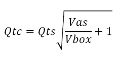
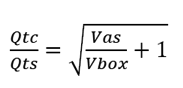
The bigger design problem is getting the woofer to resonate at 100Hz with a Q of 1 in its sealed box. We trapped ourselves by over emphasizing the 100Hz crossover frequency, rather than the Q of 1. Yes, 100Hz is a nice round number, but 93Hz or 104Hz are just as good. In other words, our goal is to first hit a Q of 1 and then aim for some frequency around 100Hz. The formula for an acoustic-suspension loudspeaker enclosure's Qc is.
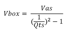
If we solve for the enclosure volume (Vbox) with a Q of 1, we get:
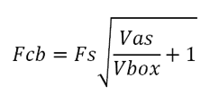
Next, we must determine the resonant frequency of the woofer in this box volume with a Q of 1.
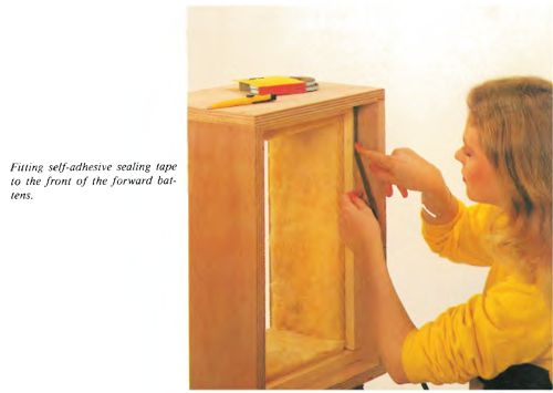
The formulas assume an empty box. Adding stuffing to the box effectively increases the box's internal volume. Within limits, of course. At some point, overstuffing actually reduces the effective volume. By the way, I am opposed to using any stuffing. Why? Muddy sound. The stuffing is analogous to adding dielectric absorption to a coupling capacitor. The air within the enclosure is essential part of the speaker system, as it controls the woofer's motion. The "acoustic-suspension" or "air suspension" loudspeaker design works due to the air within the sealed box providing more restoring force to the woofer cones movement than the woofer's own mechanical suspension, i.e. its spider and its surround. Indeed, the air provides a much more linear restoring force than the alternative stiff mechanical suspension found on music and pro speakers. Adding gobs of stuffing introduces resistance to the air's ability to control the woofer's movement, but this resistance is spread out throughout the box, which introduces dynamic non-linearity. In other words, the speaker might measure well with a steady sine-wave, but with music reproduction we hear a smearing effect. Don't believe me? Do a simple experiment: remove the stuffing from one acoustic-suspension loudspeaker enclosure (remove the woofer and pull out the stuffing) and then play a mono music track, holding a shootout between the stuffed loudspeaker and the un-stuffed one. I know which one I would place my bet on being the better sounding one. Wait a minute, John, every damn speaker maker in the world stuffs their enclosures to the maximum. People routinely do all sorts of crazy things. If you hold that shootout, however, you will probably find that the un-stuffed box sounds far less muddy, but a bit shouty. The workaround that was used in the 1940s was to attach sound-absorbing material, say ½-inch felt or 1-inch fiberglass batting, to the back panel and top panel and one side panel; that's it, only three of the six internal panels. The more exuberant covered all the interior walls, but did not stuff it any further. (I have used ¼-inch ridged Sorbothane vibration-damping sheets on all internal enclosure surfaces to great effect.)
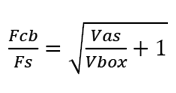
When the "acoustic-suspension" loudspeaker design was invented in the mid-1950s, filling the box with stuffing was seen as an effective cheat to making the box appear to the woofer as being bigger than it actually was. The obsession back then was to get the lowest frequency response possible; bass clarity was a secondary consideration. Soon, the belief arose that the more stuffing the better. A better approach would have been to avoid parallel walls within the enclosure and apply a moderate amount of sound-absorbing material to the inner walls. Returning to the math behind the acoustic-suspension enclosure, we note that these two formulas are related. Indeed, we see that both can be rearranged thus;
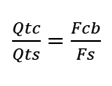
and, therefore,
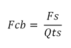
Since our target Qtc is 1, we see that
For example, if the woofer's Qts is 0.6 and its Fs is 45 Hz, then when the woofer is placed in a sealed box large enough to produce a Qtc of 1, the resonant frequency will be equal to 46/0.6 or 75Hz. To hit a target frequency of 100Hz, the woofer's Fs must be 60Hz, as 60Hz/0.6 = 100Hz; or its Q must be 0.45, as 45Hz/0.45 = 100Hz. The formulas for a 2nd-order low-pass filter with a Q of 1are: C = 159155/R/Fc where the capacitor value is in µF. Returning to the circuit, do not forget that the two 10k feedback resistors are needed. The low-pass filter OpAmps must be high-voltage types, such as the LTC2057HV. The first stage is an inverting amplifier with an attenuation of about -32.5dB for low-frequencies below 10hz with its 1Hz low-pass filter function; in other words, it reduces the low-frequency output at from the external power amplifier by 1/42. The internal bridge amplifier yields a gain of 42, so we are back to unity. If a class-D amplifier power amplifier were used instead, we would have to alter the gain reduction from the inverting input stage. For example, a common gain setting for many class-D amplifier modules is 1:20 or 26dB. In this case, we would replace the 665k resistor with a 316k resistor. I should explain the math behind these values. The 1st-order 1Hz low-pass filter puts its crossover frequency two decades below the 100Hz crossover, as 1hz to 10Hz and 10Hz to 100Hz each count as one decade. The 100Hz high-pass filter's output will be down by -20dB or 1/10 for each decade; thus, at 1Hz, it will be down by -40dB or 1/100. The inverting amplifiers DC gain is equal to R2/R1. In this example, the gain is equal to 1,590,000/316k or 1:5, which we multiply against 1/100 or 0.01 and get 1/20 or 0.05. in other words, a twenty-fold reduction, which multiplied by the internal class-D amplifier's gain of 20 yields unity-gain. By the way, since the class-D amplifier modules usually run off either 24Vdc or 36Vdc external switcher power supplies, we would no longer need to use a high-voltage OpAmp. Unlike the bridge amplifier configuration using class-AB amplifier solid-state power amplifiers, which should be used with an 8-ohm subwoofer, class-D amplifiers should be used with 4-ohm or lower impedance subwoofers. Indeed, many are optimized for 2-ohm loads, which we can create by using two 4-ohm subwoofer woofers in parallel.
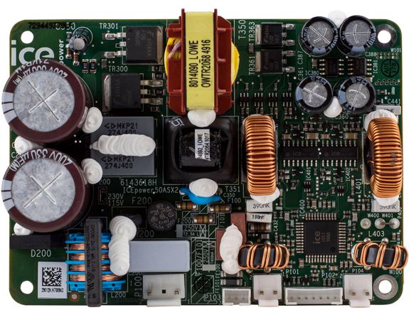
An interesting class-D amplifier module that contains its own switching-mode power supply is the ICEpower 50ASX2SE, which cost $118 from PartsExpress.com. It is a stereo class-D amplifier that can be arranged in bridge mono output that delivers 170W into a 4-ohm woofer. This arrangement requires a balanced input signal, which can easily be created with OpAmps.
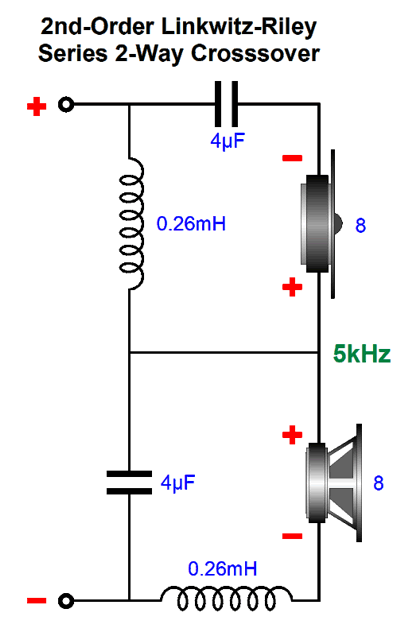
What makes this class-D amplifier module special is that also provides an additional raw bipolar power supply with +/-25Vdc (0.2A) outputs, which we could easily regulate down to +/-15Vdc power-supply rails, a convenient power supply for the OpAmps. I do not see any heatsink on the PCB, so I would be sure NOT to place it a loudspeaker enclosure filled with stuffing, as it will need good air circulation due to convection air currents. I would mount it vertically on the back wall with at least 1/2-inch hex spacers. In the in bridge mono arrangement, its efficiency is 81%, so with 170W of output power the module will dissipate about 32W. In general, we can expect average power outputs closer to 17W. Its gain is stated as being 27dB, which translates into each amplifier presenting a gain of 11. The module contains an enable pin, which when grounded shuts down the amplifiers. Okay, let's return to the crossover portion of the design. The previous design created a symmetrical 3rd-order two-way crossover by using the woofer's own intrinsic 2nd-order high-pass filter function due to it being loaded in an acoustic-suspension enclosure and its in-cabinet resonance occurring at the crossover frequency. This works, but it does not come close to the protection offered by a true 3rd-order crossover. Remember that although the woofer's output conforms to a 3rd-order cutoff, the actual voltage leaving the external power amplifier conforms to a 1st-order filter, not a 3rd. If we can ensure that the woofer's in-box resonance is far enough away from the crossover frequency (say in a dipole setup), we can use a passive 2nd-order filter that will combine with the 1st-order filtering from the external crossover before the power amplifier to create a "true" 3rd-order crossover.
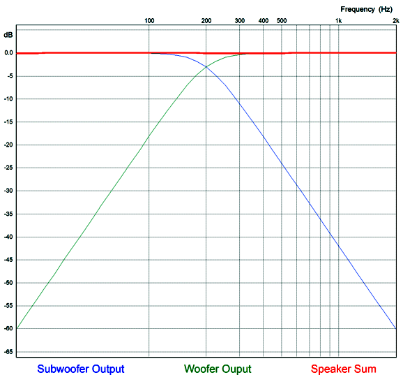
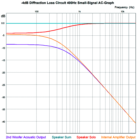
Note that the tweeter sees two crossover frequencies, 200Hz and 3kHz, which affords extra protection. In addition, both the woofer and tweeter are blind to DC offsets from the external amplifier. Alas, the subwoofer isn't so lucky, as any DC will be amplified. This assumes, of course that the internal subwoofer amplifier is DC coupled at its input. If it is a class-D effort, this is not likely. Even with a DC coupled internal subwoofer amplifier, we cap place a coupling capacitor between the external amplifier's output and the 634k feedback resistor. A 0.1µF capacitor will impose a -3dB frequency of 2.5Hz; plenty low. The passive 2nd-order filter made up of the 100µF capacitor and 6.4mH inductor produce a Q of 1, which cascading with the 1st-order filter's Q of 0.707 results in a final Q of 0.707. Note that the capacitor value matches what it would be for a 1st-order passive filter; so, too, the inductor's value. Here is the formulas: C = 159155/R/Fc L = 1000 x R/(6.283 x Fc) where the capacitor value is in µF; and the inductor, in mH. Note that 0.1µF capacitors were used throughout the active filters. Why? We can easily buy 1% tolerance 0.1µF capacitors, but not so much other capacitor values. This explains the two 10k negative-feedback resistors in the 2nd-order active low-pass filter; they are needed to create a Q of 1 with equal capacitor values. This setup would work best if the subwoofer's Fc frequency was also 50Hz, so as to match the woofer's. Otherwise, we can expect phase shifts to undo the ruler flat output. Speaking of output, here is the SPICE generated graph for the circuit.
Okay, what if we desire a phase-flat loudspeaker? The easiest solution is the 1st-order crossover.
The assumption here is that a small-power external amplifier is used—or that a robust tweeter is used. True, the tweeter will see 200Hz crossover filtering along with its 3kHz filter, but that still makes huge demands on the tweeter. In addition, we would have to time align the tweeter with the woofer. Note the phase reversal at the subwoofer's connection to its internal amplifier; we must undo the phase flip from the inverting amplifier.
Correcting Woofer Non-Linearity
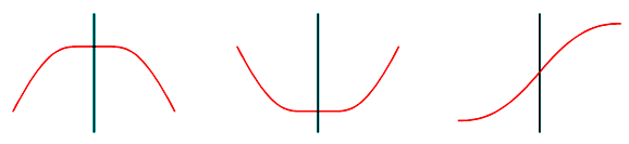
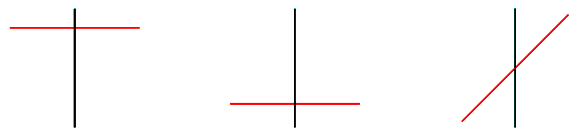
Our ear hears this non-linearity as a form of compression, which we seek to overcome by increasing the volume, which only makes the compression worse. This distortion occurs most at low frequencies, as deep bass requires big cone movements. (Tweeters can blast away and yet the diaphragms barely move.) If the woofer was perfectly linear, this is what the graph plotlines would look like.
One workaround is to use negative feedback from the woofer's cone to force greater linearity. This usually takes the form of a servo system of sorts that only applies over a limited low-frequency bandwidth. The woofer's cone's movements are sampled through either an accelerometer or capacitance sensor or an LED and photo-transistor or a secondary voicecoil; then the negative feedback system compares the cones actual movement to the input signal and makes the needed corrections. Yes, this can work and it can sound fantastic. Of course, it works best at low frequencies, less well with higher frequencies. An alternative approach would be to pre-distort the signal fed to the power amplifier, so that the inverse countervailing distortion would cancel the woofer's distortion. In other words, a countervailing non-linearity is used to force linearity.
Well, after noting in the post 551's topic of diffraction loss that the secondary woofer's output was significantly lower than the primary woofers' output, I wondered if the secondary woofer could do more than correct for diffraction loss, as in also correct for woofer non-linearity.
The idea is simple, at low volume levels, the secondary woofer only corrects diffraction loss, but as the signal level increases, a countervailing non-linearity is added to the secondary woofer's input signal. How do we create such a non-linear function? Here is one idea I had.
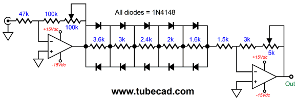
The ultra-fast signal diodes only come into play when sufficient voltage develops across them to make them forward biased, about 0.6V. When a diode begins to conduct, however, it locks the voltage drop across its leads and effectively becomes a short to AC signals, which prompts an increase in signal gain from the amplifier. Considering that there are five diodes in series, it would take at least 3Vpk to forward bias all of them, whereas most signal sources, such as CD players and FM tuners, put out between 1Vpk to 2Vpk. Since we would use the output voltage swings delivered to the loudspeaker from the external power amplifier, we have far more voltage than we need. For example, 100W into an 8-ohm speaker means +/-40Vpk voltage swings. This circuit assumes a small power amplifier that can deliver 16W, which equals 16Vpk into an 8-ohm load. The circuit first reduces the 16Vpk swing to +/-3.4Vpk through the 47k and 10k resistors. It further reduces the swings to +/-1Vpk through the next inverting OpAmp's negative feedback resistor, which is important for two reasons. The first is the OpAmp runs off +/-15Vdc power-supply rails, which means that its peak output voltage swing is about 12Vpk. The second is that the loudspeaker's internal power amplifier is not likely to prove unity-gain stable. Indeed, the LM3886 is barely stable at a gain of 1:10 (20dB), so a safer approach would be to set its gain to 1:16 (24dB), which the 1Vpk of input signal is enough to drive it to full output. Here is the SPICE-generated graph.
The X axis shows the input signal derived from the external power amplifiers output voltage swings, while the Z axis shows the resulting OpAmp's output voltage. Since the two inverting amplifier in series preserve the phase, there's no need to flip the phase at the woofer's terminals. Note that the relation is linear up to -/+7Vpk of external power amplifier output; beyond this range, in either direction, the circuit's gain climbs. The goal is to produce an inverse curve to the woofers non-linearity. Will this curve match your loudspeaker's woofers? I doubt it, but it will certainly match some woofer. In other words, this is a proof of concept, not a universal fix-it circuit.
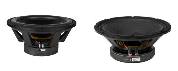
Here is an interesting philosophical question for you: what are the main differences between high-end-audio woofers and music woofers used by musicians? They do differ, so much so that the sellers of loudspeaker drivers place them in two distinct categories. Cost is not the key difference, as we can buy some very expensive professional audio woofers. A list of differences would include efficiency, with pro woofers offering far higher SPL per watt; mechanical Q (Qms), with high-end woofers exhibiting far lower Qms; resonant frequency (Fs), with pro woofers resonating at a higher frequency; the mechanical compliance of suspension (Cms), with pro woofers using a far stiffer suspension, hence a low Cms (compliance is the inverse of stiffness); and, last, the maximum linear excursion (Xmax), with high-end woofers offer greater Xmax. I am sure other near universal differences could be listed, such as rubber surrounds versus folded cloth, flatter rather than peaky frequency response, but the maximum linear excursion is must be viewed as the key difference. In fact, we might come up with a figure of merit based on Xmax²/Xlim, with Xlim being Xlim the maximum mechanical excursion before damage is expected. Music/pro speaker drivers must play loud, first and foremost; high-end woofers must play accurately. The design of each type entails making sacrifices. The pro woofer must sacrifice low-frequency extension, mechanical damping, and linear excursions of the cone. The high-end woofer must sacrifice efficiency. Where the pro woofer uses a short voicecoil that fits snugly in the magnetic gap, the high-end woofer must employ a long voicecoil that over hangs on both sides of the magnetic gap, which increases linearity. Moreover, to get a low resonant frequency, hence good low-frequency response, a high-end woofer must use a higher compliance surround and spider to allow long slow vibrations and a heavier cone. Horn-loaded woofers do not move much at all, as the horn functions as an acoustic transformer that efficiently couples the heavy and small cone to a huge area of light air. I once owned a single Klipsch corner horn loudspeaker; its 15-inch woofer was decidedly not a Hi-Fi type, but something closer to a music/pro type. Whatever other failings a horn loudspeaker may suffer from, a compressed sound is not one of them. Well, much like horn-loading, it's possible that this inverse-linearity circuit could make otherwise not hi-fi pro woofers more linear, thus more hi-fi, while retaining the high efficiency. The pro woofer would still suffer from a high mechanical Q and truncated deep-bass response, but it might make a hell of a satellite speaker woofer. Imagine a pro 10-inch woofer (along with a high-SPL tweeter) with this inverse-linearity circuit and 100Hz high-pass filter and powered subwoofers. It could prove amazing. Okay, returning to the inverse-linearity circuit, we can do away with the input differential amplifier, if the woofer is terminated into ground, which it might not be with some crossover types, such as the series 2nd-order type.
The differential amplifier allows us to sample the voltage across the woofer in spite of the woofer not being grounded. With the grounded woofer, we can use this variation.
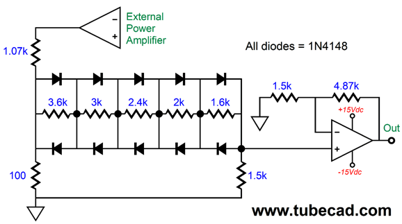
This time the assumption is that a 100W external power amplifier is driving the loudspeaker; thus, the greater attenuation wit the 1.07k and 100-ohm resistors. This circuit aims to undo the woofer's limited linear motion, but does not compensate for diffraction loss resulting from a small enclosure relative to the large bass wavelengths. Adding this extra correction requires adding one capacitor.
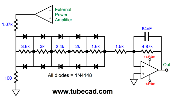
The capacitor imposes a 1st-order low-pass filter function on the output, with a 64nF (0.064µF) capacitor imposing a 510Hz transition frequency. If this frequency sounds familiar, it is due to being the needed transition frequency in the previous post's example of a shelving network to undo the low-frequency loss due to diffraction. Do you note a developing pattern here? If the external power amplifier produced 8Vpk of output voltage swing, what would an LM3886-based power amplifier with a gain of 1:20 produce as output with this circuit driving it?
Returning to the 16W version and the flea-power amplifier, here is the schematic and graph again.
We examine the graph above and see that at 8Vpk the circuit delivers 0.235V of output, which against a gain of 1:20 equals 4.7V, which is what is needed to undo the diffraction loss in the design example from that previous post. The idea was that a secondary woofer (powered by an internal power amplifier) would only fill in the dip in deep bass due to diffraction loss.
We could other version, the one designed for 100W amplifiers. Of course, a flea-power amplifier will never get close to delivering 100W (40Vpk), so the inverse-linearity portion of this circuit would not come into play, only the diffraction correction, but it would make the speaker more universal, rather than be limited to just tiny amplifiers.
Correcting Subwoofer Non-Linearity
The input OpAmp delivers a gain that can span form 1:3 to 1:5; in other words, the potentiometer offers fine-tuning of the gain for the inverse-linearity circuit. The diodes do their magic and the second OpAmp drives the low-pass filter; the potentiometer at the output allows us to match the satellite speaker volume. Finally, either an external or internal power amplifier drives the subwoofer driver.
Correcting Two-Way Speaker Non-Linearity
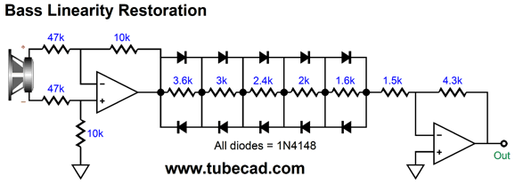
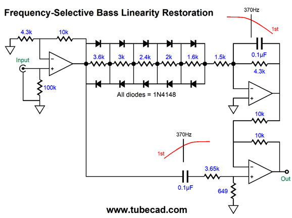
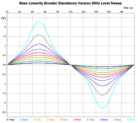
The leftmost OpAmp simply applies a little gain, so the diodes can "catch" on big voltage swings. In addition, its low output impedance ensures exact tuning of the low-pass filter formed by the 0.1µF (100nF) capacitor and the 3.65k and 649 resistors. The transition frequency is 370Hz, with gentle 1st-order slopes. The frequency response is flat as long as the input signal is small. If 1Vpk at 50Hz goes in the input, 2.22Vpk output comes out; if 1Vpk at 5kHz goes in the input, 1Vpk output comes out. The boosted 50Hz sinewave looks quite distorted, which is what we want, as it is meant to present the inverse of the woofer distortion.
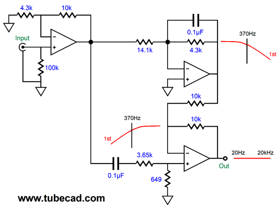
In contrast, the 5kHz looks quite clean, which is what we want. If the signal amplitude is low, both sinewaves look perfect, as none of the diodes becomes forward biased and the circuit reduces to the following:
The 14.1k resistor represents the combined total resistance of the six resistors in series. As we see, a low-pass filter's output is combined with high-pass filter, with both tuned to the same frequency. Since the filters are 1st-order types, the result is phase flat with no phase inversion. Now, if we are willing to get sneaky, we could carefully select the internal crossover frequency and the bass level to undo the shelving effect due to diffraction loss. In other words, we would further woofer linearity and flatten the bass response. (As always, it's a good thing I am not a patent attorney.) This circuit would go between the signal source, e.g. a CD player, DAC, or line-stage amplifier, and the power amplifier. Two potentiometers should be added, one at the input and one at the output, so some fine tuning could be applied.
Tube Versions
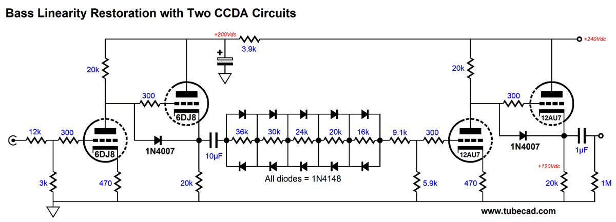
The constant-current-draw amplifier (CCDA) comes in handy, twice. The 6DJ8-based CCDA offers a gain of 1:16, so an input attenuator is needed to reduce it; thus, the 12k and 3k resistors. The 10µF internal coupling capacitor is needed due to the potentially low impedance presented by the diode strings. The 9.1k and 5.9k resistor further reduce the gain before the 12AU7-based CCDA amplifies the signal. How would we make a tube-based frequency-selective bass linearity enhancer circuit? We must combine two signals, each bandwidth limited.
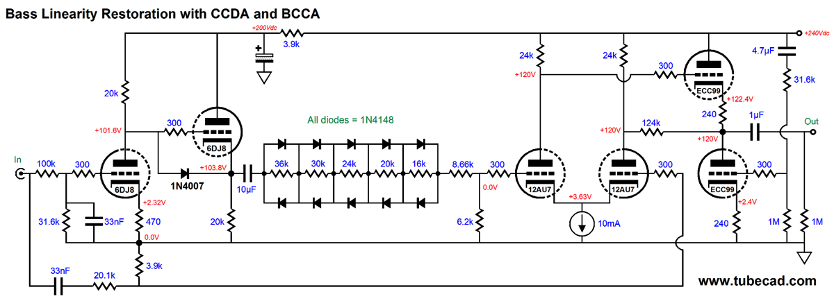
The BCCA stands for Broskie cathode-coupled amplifier. You have seen the circuit here before, in post 413 for example, but under different names.
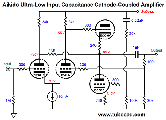
The secret sauce consists of two features. The first is the Aikido cathode follower output stage; the second, the resistor that spans from one plate to the output. The ACF improves the PSRR and presents a low output impedance. The added resistor raises the AC input impedance, as the leftmost triode's plate sees the AC signal as the grid below it. As configured in the bass-linearity circuit, however, the BCCA functions as a differential amplifier; in the schematic shown above, as a line-stage amplifier with fixed gain due to the negative feedback loop. The input signal gets split down two paths and two filters, one low-pass and one high-pass, both tuned to the same frequency, which in this example is 380Hz. The same valued capacitor (0.33µF) is used in both filters as 100k || 31.6k equals 20.1k + 3.9k which also equals 24k.
Music Recommendation: Not Music I do remember, however, being irked by those who told me that they also loved jazz, especially Kenny G. (He is in the top 25 biggest album sellers of all time.) Once again Nietzsche comes to mind, "And those who were seen dancing were thought to be insane by those who could not hear the music." When it came to Kenny G's music, I couldn't hear it. From birth on, I grew up hearing Coleman Hawkins, Johnny Hodges, Ben Webster, Lester Young... Well, after listening to this podcast, I will make the effort to give Kenny G a listen. Why? Just to hear what I am missing or not missing. . //JRB
Did you enjoy my post? Do you want to see me make it to post 1,000? If so, think about supporting me at Patreon.
User Guides for GlassWare Software
For those of you who still have old computers running Windows XP (32-bit) or any other Windows 32-bit OS, I have setup the download availability of my old old standards: Tube CAD, SE Amp CAD, and Audio Gadgets. The downloads are at the GlassWare-Yahoo store and the price is only $9.95 for each program. http://glass-ware.stores.yahoo.net/adsoffromgla.html So many have asked that I had to do it. WARNING: THESE THREE PROGRAMS WILL NOT RUN UNDER VISTA 64-Bit or WINDOWS 7, 8, and 10 if the OS is not 32-bit or if it is a 64-bit OS. I do plan on remaking all of these programs into 64-bit versions, but it will be a huge ordeal, as programming requires vast chunks of noise-free time, something very rare with children running about. Ideally, I would love to come out with versions that run on iPads and Android-OS tablets.
|
Special Thanks to Lee Grantham
I know that some readers wish to avoid Patreon, so here is a PayPal button instead. Thanks. John Broskie
John Gives
Special Thanks to the Special 82 To all my patrons, all 82 of them, thank you all again. I want to especially thank
All of your support makes a big difference. I would love to arrive at the point where creating my posts was my top priority of the day, not something that I have to steal time from other obligations to do. The more support I get, the higher up these posts move up in deserving attention.
If you have been reading my posts, you know that my lifetime goal is reaching post number one thousand. I have 447 more to go. My second goal was to gather 1,000 patrons. Well, that no longer seems possible to me, so I will shoot for a mighty 100 instead. Thus, I have just 18 patrons to go. Help me get there. Thanks.
Support the Tube CAD Journal & get an extremely powerful push-pull tube-amplifier simulator for TCJ Push-Pull Calculator
TCJ PPC Version 2 Improvements Rebuilt simulation engine *User definable
Download or CD ROM For more information, please visit our Web site : To purchase, please visit our Yahoo Store: |
|||


| www.tubecad.com Copyright © 1999-2021 GlassWare All Rights Reserved |