| John Broskie's Guide to Tube Circuit Analysis & Design |
22 December 2021 Post Number 550 (55% there!)
Merry Christmas!
Intriguing how none of her desired gifts are desired today—the possible exception of the Club Coupe.
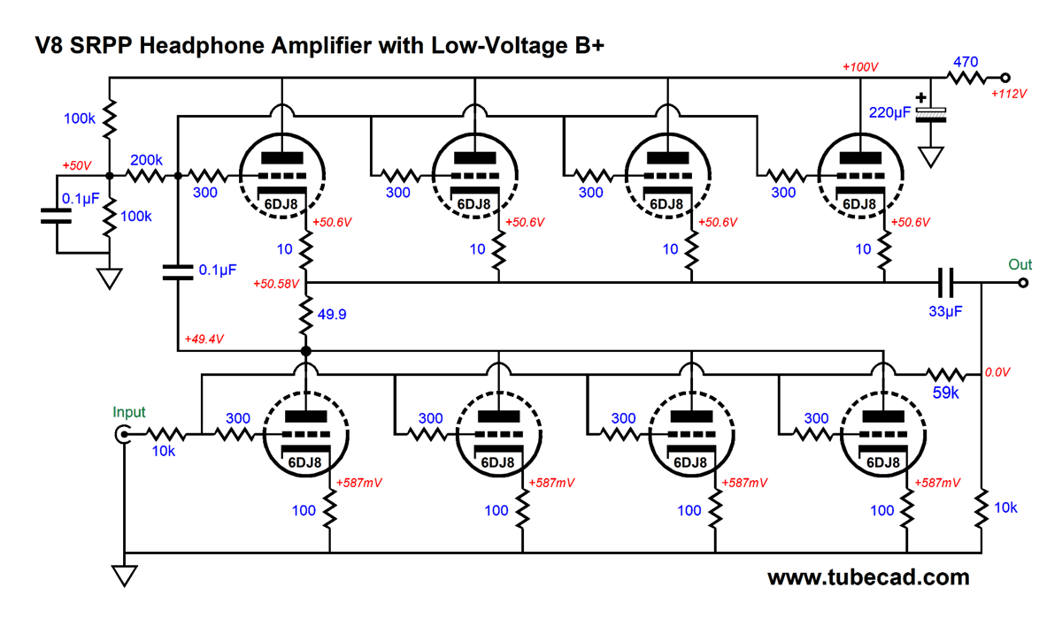
V8 SRPP Headphone Amplifier
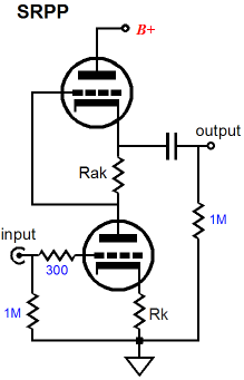
What if you own high-impedance headphones, on the other hand, such as the 300-ohm Sennheiser types, for example the HD580 to HD820? Well, we wouldn't need such a large-valued output coupling capacitor, and we could resort to a far simplified design, i.e. the SRPP topology. Moreover, with the SRPP topology, we forgo the need for both an input stage and the phase splitter, as we will effectively place four SRPP stages in parallel.
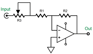
Because it is simple, the SRPP is beloved. One twin-triode tube and few resistors are all that is needed to gain entry into the wonderful world of tube audio. In spite of its simplicity, the SRPP confuses many. For over two decades, I have been told many conflicting narratives of how the SRPP functions—from it being fundamentally a single-ended circuit to it being basically a digital circuit. Few like to view it as I do—namely, that the SRPP is fundamentally a push-pull circuit on the cheap, as no external balanced input signal or internal phase splitter is required. (My meta view is that the top triode actually functions as an impedance-multiplier circuit.) To achieve the small miracle of balanced push-pull operation, the SRPP must be "tuned" to one ideal load impedance. In other words, the SRPP is load-dependent. Since we have already specified 300 ohms as the intended load, we must design for that load impedance. Sadly, the tube-manual specifications for the 6DJ8 and the famous formula for finding the top cathode resistor value will not get us close enough, as the 6DJ8 will only see a 50-volt cathode-to-plate voltage drop, so the triode's plate resistance will prove higher than expected, while the transconductance will prove lower. SPICE comes to the rescue. In SPICE simulations, we can measure the current swings between top and bottom triodes into a 300-ohm load, and then vary the part values until we arrive at the optimal value. Will these values exactly translate into reality? I doubt it, but they will get us very close indeed. After an hour of part-value fiddling, here is the result.
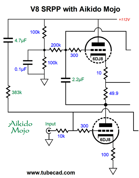
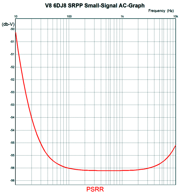
All four of the bottom 100-ohm cathode resistors are unbypassed, which does increase the output impedance and reduce the gain, but it also lowers the higher-harmonic distortion. A fair exchange, as far as I am concerned. The four top 10-ohm cathode resistors are there only to ensure an equal current draw by each of the top triodes. (Probably, the resistors could be dispensed with, but I would include them for peace of mind.) SPICE simulations revealed that the all-important current-sense resistor value was 49.9 ohms for the 300-ohm load impedance. If you eschew metal-film resistors, a 51-ohm carbon-film resistor or two 100-ohm carbon-film resistors in parallel could be used. The open-loop gain is close to 1:8 (+18dB); the output impedance, 390 ohms; and the THD is about 0.1% with 1Vpk of output. Even with the 300-ohm load impedance, its damping factor is dismal. With an inverting negative feedback loop in place, however, the gain falls to 1:3.16 (+10dB); the output impedance, 90 ohms; and the THD is about 0.035% with 1Vpk of output. The 10k input resistor and the 59k resistor at the output form the negative feedback loop for this inverting amplifier. The assumption here is that a low-impedance signal source will drive this V8 headphone amplifier, such as a DAC or smartphone or personal music device. In other words, the 10k input impedance will not burden the signal source. On the other hand, if a wimpy tube-based line-stage amplifier is used, say one with a 12AX7 output tube and a 0.047µF output coupling capacitor, we will end up with dismal sonic results. In addition, the inverting negative feedback arrangement means that we cannot use a conventional volume potentiometer in front of the 10k resistor, but those previously listed signal sources usually come with a digital volume control, there is no pressing need for the volume potentiometer. The only aspect of the circuit's performance left unexplored is its PSRR. It's okay, but not great, coming in at -21dB. Fortunately a simple Aikido mojo addition of just one resistor and capacitor per channel increases the PSRR to -55.5dB at 100Hz.
The added capacitor and resistor allow a small percentage of the power-supply noise to mix with the input signal, resulting in a huge improvement in PSRR.
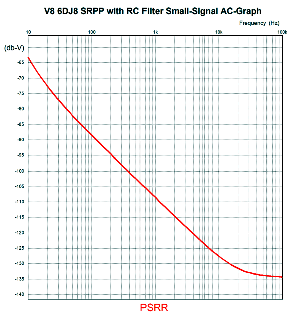
This is the raw PSRR, with no further power-supply noise filtering other than the Aikido Mojo. If we give each channel its own B+ voltage RC filter, say a 470-ohm resistor and 150µF capacitor, the PSRR improves even more.
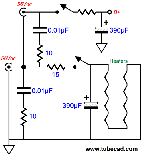
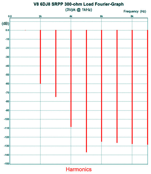
Since the assumption here is that two 56Vdc switching power supplies will power the V8 headphone amplifier, the switching frequency will not be 50Hz or 60Hz, but something closer to 50kHz. Inspection of the graph shows a huge attenuation of -133dB at 50kHz. The 4.7µF and 2.2µF capacitors may seem to be excessively large in value, but they are needed to ensure a power-supply noise null that extends down to 100Hz—just in case a conventional high-voltage power supply were used. With a total idle current flow of about 24mA per channel, the class-A amplifier window of operation should extend beyond 12Vpk. I cannot imagine anyone playing that loud; nor do I believe that the headphones could survive so hot an output signal. With a more reasonable output voltage swing of 3Vpk, the THD in SPICE simulations came in close to 0.1%.
Note the extreme attenuation of the 5th harmonic. Nice. With a 20µF film output coupling capacitor, the bandwidth extended from 5Hz to over 500kHz. Building this headphone amplifier would not prove too difficult if wired point-to-point, but a PCB would make life far easier. The huge time saver, however, comes from using two cheap 56Vdc switcher power supplies. If we were willing to forgo this time saver, we could build a conventional power supply, which would allow us the ability to use a much higher B+ voltage, say 200Vdc, which in turn would deliver greater performance, but reduced tube life. By the way, I have received some criticism for not getting it. "It" being the proper way to design audio gear: first step is to forget about topology; second step is to buy the most expensive parts; third step is to place a $10,000 price-tag on the device. This view holds that topological development is impossible, as anything that could be invented was invented by about 1940. It also maintains that $10 resistors and $300 coupling capacitors always bestow sonic glory. It's last piece of wisdom is that the more expensive the audio product the better it must sound, ipso facto! There is a great story about Enzo Ferrari dismissing aerodynamics as it being only suitable for cars with little horsepower—until he began losing races to cars with much less horsepower. Well, we can say the same about topology analysis, as it is only suitable for audio equipment for those with limited budgets—until we hear far better sounding gear that costs half as much.
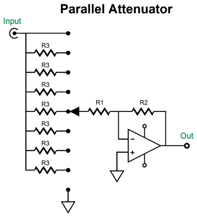
Parallel Stepped Attenuator
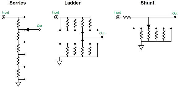
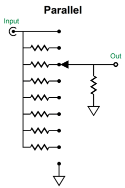
What if we flip the shunt attenuator and place fixed resistor at the bottom, so it terminates into ground, while array of many parallel resistors terminates into the input signal?
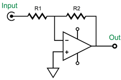
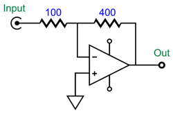
Where the shunt uses a large-valued series resistor and many lower-valued arrayed resistors, this "parallel" attenuator uses a low-valued shunting resistor and many higher-valued arrayed resistors. Like the shunt attenuator, this parallel attenuator does not present a constant input impedance. In short, the parallel attenuator looks like a giant step sideways compared to the shunt attenuator. In terms of input impedance, however, it is an improvement relative to the signal source, as the parallel attenuator's input impedance rises with increased attenuation, thereby unloading the signal source; in terms of resistor noise, the parallel attenuator is worse than the shunt at extreme attenuation. Okay, let us move away from theoretical to practical. The SRPP-based V8 headphone amplifier shown above is an inverting amplifier whose negative feedback loop sets the final output gain. The larger the (R1) input negative feedback resistor's value, the lower the gain; the smaller the value, the higher the output gain. Let's leave the V8 behind and abstract to any inverting amplifier; indeed, we will use the "ideal" OpAmp, which is an abstraction of a perfect amplifier.
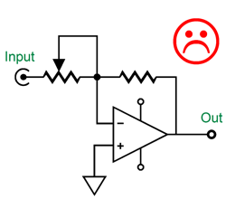
The formula finding its gain is embarrassingly simple: Gain = R2/R1 or, in dBs, Gain in dB = 20Log(R2/R1) What if we vary resistor R1's value to create a volume control? The simple way to implement this arrangement is to replace the input resistor with a potentiometer.
The sad face is due to the potentiometer presenting its full resistance at one end, but zero impedance at the other end. Not good, as the signal source would effectively see a dead short to ground at its output. The simple workaround is to place a resistor in series with the potentiometer.
Now, the input impedance cannot fall below R1's 100 ohms.
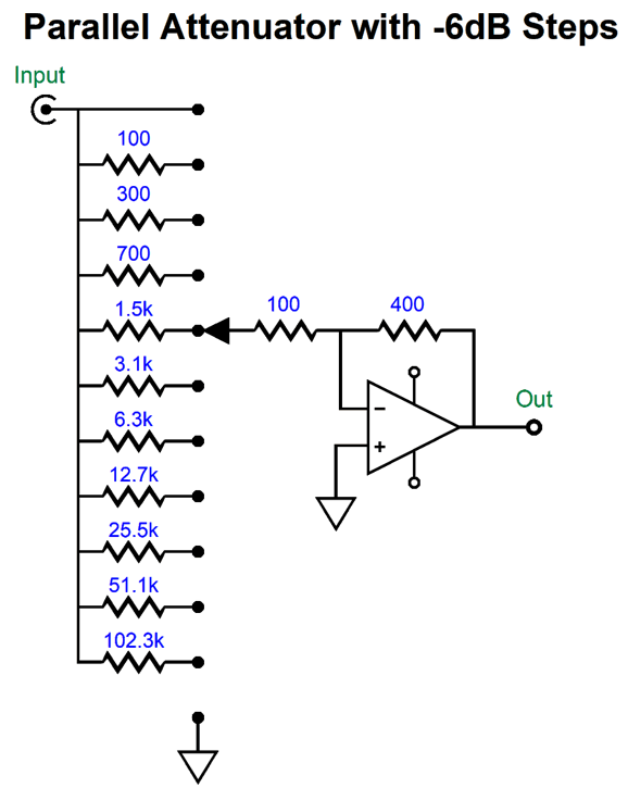
While 100 ohms might seem a crazy low input impedance, the assumption was that we had a headphone amplifier whose intended signal source was an existing headphone amplifier inside a personal-music player or smartphone, whose intended headphone impedance was as low as 16 ohms. In other words, the 100-ohm load will prove a relief. (On the other hand, a DAC or CD player or music server would be much happier with a 10k load.) Which potentiometer resistance should we use? The maximum gain is equal to 40k/10k or 1:4 of +12dB. Let's say we want a maximum attenuation of -60dB, which means that an input signal of 1Vpk would come out at 1mVpk, a thousand-fold reduction. The quick answer is that the potentiometer resistance should be 1,000 times larger than R2 (minus R1's 100 ohms) or 400k – 100 or 399.9k—an awkward value, as the closest potentiometer value is 470k. in addition, the potentiometer must be a logarithmic type, whose tracking between channels is not nearly as precise as the linear type. The workaround would be to use a many-positioned rotary switch instead.
The series arrangement of the resistors means that the worst-case scenario is all the resistors and all the solder joints in series with the signal. On the other hand, if we place the resistors and the switch contacts in parallel, the worst-case scenario is one resistor and two solder joints in series with the signal. The rotary switch should be a make-before-break type in both arrangements. Ideally, the switch contacts should be either hard gold or at least be available for easy cleaning with contact spray cleaner. The formula for finding the parallel arrangement resistor values is simple enough: R3 = R2/(10^[dB/20]) – R1 What we gain with this attenuator arrangement is not just precise attenuation steps, but lower distortion at extreme attenuation, as we are effectively increasing the amount of negative feedback with increased attenuation. With the V8 SRPP headphone amplifier, for example, the THD lowers by about -20dB (tenfold) at -60dB of attenuation compared to reducing the input signal amplitude by -72dB. (Do not forget the that the SRPP headphone amplifier offers a gain of 1:4 or +12dB, so the input signal must be attenuated by an additional -12dB to get to the output being -60dB.)
What we lose is a reduction in output noise due to the increased resistor noise. All resistors create noise due to the thermal agitation of the atoms within the resistor. With the inverting amplifier, the resistor noise source is equal to the negative feedback loop resistors (R1 and R2) being in parallel with each other. So with 100-ohm and 400-ohm resistors in parallel, we get 80 ohms of resistance. With the parallel attenuator at -60dB of attenuation, the parallel resistance comes in at 399.6 ohms, roughly five times more. Mind you, 399.6 ohms does not create a lot of noise, even with headphones and an amplifier gain of 12dB. Tube-based audio gear uses much higher resistor values, however, so we must worry a bit more. How much more? So little that I wouldn't worry about it, as the tube-generated noise will be far higher. Something I would worry about is the question of will the Aikido-mojo trick used in the V8 SRPP headphone amplifier shown above still work? No, as it assumed that the 10k input resistor terminated into a low-impedance signal source.
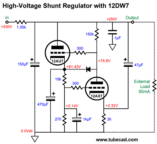
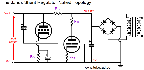
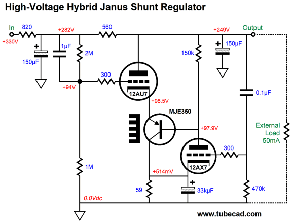
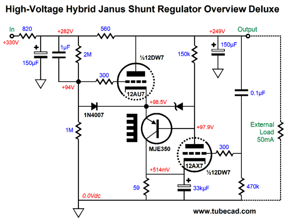
Simple Hybrid Janus Regulator
The 12DW7 is a twin-triode tube that hold dissimilar triodes; in this case, a 12AX7 and 12AU7 triode. The B+ voltage noise is relayed to the 12AX7's cathode through the 47µF capacitor, where the 12AX7 amplifies the noise at its plate—in phase. The 12AU7 triode then varies its current conduction in anti-phase to the amplified noise, thereby reducing the noise's amplitude. So far, this functioning is just a shunt regulator; by terminating the 12AX7's plate resistor on the other side of the series resistor, however, we introduce the Janus looking both ways feature. With this change, the regulator still uses negative feedback to eliminate power-supply noise at the output and now adds feed-forward feedback to undo the ripple from the raw power supply on the other side of the series resistor.
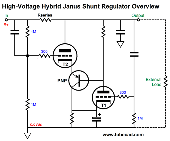
In the Janus topology, the series resistor's value becomes critical, as either too low a value or too high a value will not yield the deep ripple null we seek. Since the 12AX7 triode presents a plate resistance (rp), not all the raw power-supply noise appears at the 12AU7's grid, as the plate resistor and the rp define a two-resistor voltage divider to the ripple. Thus, we cannot simply specify that the series resistor value equal the inverse of the 12AU7's transconductance, but some higher value. In the following Janus hybrid, all of the raw power-supply noise is injected into the triode T1's grid.
Note that all the high-voltage, high-valued capacitors are gone. The input stage no longer consists of a grounded-grid amplifier, but a grounded-cathode amplifier. Since the triode's grid presents a hugely high input impedance relative to its cathode, we can use a 0.1µF film capacitor in place of the grounded-grid amplifier's 47µF capacitor to relay the AC noise on the output voltage to the input tube.
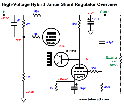
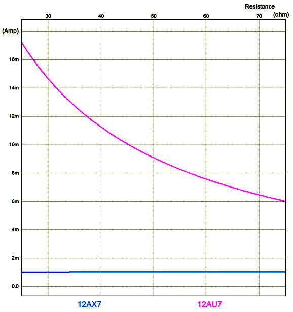
True, the 12AX7 cathode resistor is bypassed by a huge capacitance (33kµF), but it is low-voltage capacitor, as in 6.3V to 10V. At first, I thought that here was a job for an ultracapacitor/supercapacitor, but then I noted the relatively high ESR and DC leakage current for these battery replacement capacitors. The best choice would a low-impedance electrolytic, such as the Panasonic FC series of capacitors—except that Panasonic does not make a 33kµF/6.3V capacitor in that series. Nichicon offers the UVY0J333MRD, which is at least a 105C-rated capacitor. The PNP transistor's collector resistor and the input stage's cathode resistor (59 ohms) are one in the same. This arrangement allows DC negative feedback to be used by the input stage to control the idle current flow through the 12AU7 triode. The larger the resistor's value, the lower the idle current flow through the 12AU7 triode. Here is a SPICE-generated graph that shows the changes in current flow for both triodes relative to the resistor's resistance.
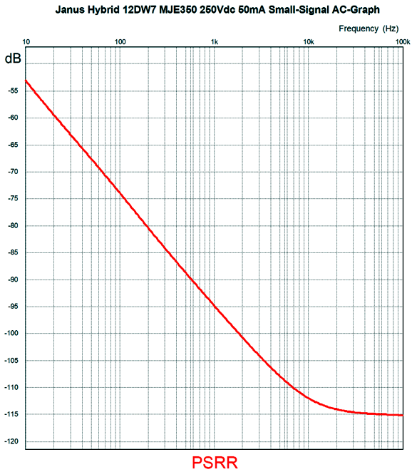
Note how the 12AX7 triode draws a nearly constant current, while the 12AU7 triode's varies with the change in resistance. In addition, this DC negative feedback allows us to DC couple the input and output stages throughout. Bear in mind that this regulator only cleans up the AC portion of the output voltage, but does not established a fixed DC output voltage. Since shunt regulators should never be used to power a class-AB power amplifier but class-A amplifiers found in phono preamps and line-stage amplifiers, an absolutely fixed DC output voltage is not that essential. How well does this hybrid Janus regulator work? Here is the SPICE-generated graph showing the raw power-supply noise rejection versus frequency, without the RC pre-filter.
Better than -70dB at 100Hz is a good start. The attenuation above 10kHz can be furthered by shunting the output with a capacitor. The output impedance is below 8 ohms from 10Hz to 100kHz. By adding both an RC filter and an output capacitor, the performance improves dramatically.
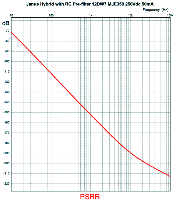
Note the higher raw B+ voltage of 330V, rather than 282Vdc. The external load draws 50mA. The following graph shows the improvement in performance.
The blue plotline shows the attenuation from the RC pre-filter, while the red line shows the final output PSRR. Considering how wimpy the 12AU7 and 12AX7 triodes are, it is amazing how much performance they can be prompted to deliver. The only thing that remains is to include some protection diodes. At startup, when the triodes are still cold and not conducting, or when the 12DW7 is missing from its socket, the PNP transistor is in danger following experiencing excessive base voltages. The workaround is to add two diodes.
The 1N4735 is a 6.2V/1W zener that limits the maximum base-to-emitter voltage to +0.7V to -6.2V. The 1N4007 rectifier protects the 12AU7 at start up.
Music Recommendation: Viviana Lasaracina's Goyescas Op. 11 Having grown up listening to and loving Alicia de Larrocha's piano work, I was stunned by the vitality and freshness that Viviana Lasaracina's playing imparted. The recording is good, but not great, sadly. This performance deserved the best sound possible. Nonetheless, it is highly recommended. Amazon Music streaming service offers it in 24-bit 96kHz.
//JRB
Did you enjoy my post? Do you want to see me make it to post 1,000? If so, think about supporting me at Patreon.
User Guides for GlassWare Software
For those of you who still have old computers running Windows XP (32-bit) or any other Windows 32-bit OS, I have setup the download availability of my old old standards: Tube CAD, SE Amp CAD, and Audio Gadgets. The downloads are at the GlassWare-Yahoo store and the price is only $9.95 for each program. http://glass-ware.stores.yahoo.net/adsoffromgla.html So many have asked that I had to do it. WARNING: THESE THREE PROGRAMS WILL NOT RUN UNDER VISTA 64-Bit or WINDOWS 7, 8, and 10 if the OS is not 32-bit or if it is a 64-bit OS. I do plan on remaking all of these programs into 64-bit versions, but it will be a huge ordeal, as programming requires vast chunks of noise-free time, something very rare with children running about. Ideally, I would love to come out with versions that run on iPads and Android-OS tablets.
|
I know that some readers wish to avoid Patreon, so here is a PayPal button instead. Thanks. John Broskie
John Gives
Special Thanks to the Special 87 To all my patrons, all 87 of them, thank you all again. I want to especially thank
All of your support makes a big difference. I would love to arrive at the point where creating my posts was my top priority of the day, not something that I have to steal time from other obligations to do. The more support I get, the higher up these posts move up in deserving attention.
If you have been reading my posts, you know that my lifetime goal is reaching post number one thousand. I have 450 more to go. My second goal was to gather 1,000 patrons. Well, that no longer seems possible to me, so I will shoot for a mighty 100 instead. Thus, I have just 13 patrons to go. Help me get there. Thanks.
Support the Tube CAD Journal & get an extremely powerful push-pull tube-amplifier simulator for TCJ Push-Pull Calculator
TCJ PPC Version 2 Improvements Rebuilt simulation engine *User definable
Download or CD ROM For more information, please visit our Web site : To purchase, please visit our Yahoo Store: |
|||


| www.tubecad.com Copyright © 1999-2021 GlassWare All Rights Reserved |