| John Broskie's Guide to Tube Circuit Analysis & Design |
10 December 2021 Post Number 549
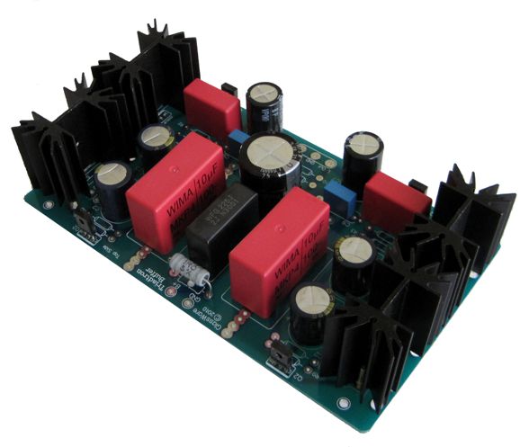
Triadtron PCB Well, I held a shootout between the tiny OTL and the best-bass-producing headphone driver I own: my Triadtron buffer. (I own three commercially-made solid-state and five tube-based headphone amplifiers; all the tube-based amplifiers are of my design). I dug out the Triadtron buffer, which requires a monopolar power-supply voltage from 12Vdc to 24Vdc, with even 48Vdc possible. If you are like me, you own many orphaned switcher power supplies from now dead or superseded electronics. I used a 24Vdc @ 4A desktop switcher, which is a gross overkill, but it was readily available in a nearby drawer. Since the circuit is a unity-gain buffer, all the signal gain must come from the signal source. (I made the PCB for my own and few friend's use, with the idea that it would be proceeded by an Aikido line-stage amplifier.) My Sony personal-music player and DAC both offered easily enough output signal amplitude to make my HiFiMan headphones sing loudly.
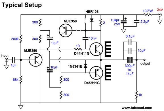
Which won the bass shootout? The Triadtron did. It delivers an impressively deep and tight bass. The power buffer's frequecy response is ruller flat, so no bass boost was imposed. Well, I gave my old Triadtron an extended many-hour listen and I was quite impressed by the sound, all the sound, both bass and the rest of the audio bandwidth even without a tube preamp driving it. Very single-ended sounding, which makes sense, as the circuit is fundamentally a single-ended one. Appearances to the contrary, the output stage is not a push-pull type—as long as the output current does not exceed the idle current flow. If forced past this threshold current, the circuit switches to push-pull output. Since my build runs a very heavy 200mA of idle current per channel, it remains in single-ended mode. The way it works is that the NPN output transistor runs under a constant-current flow, so it mimics a constant-current source, while the PNP transistor below it varies its current flow as needed to maintain the constant-current flow of the NPN transistor above it. When the PNP transistor ceases to conduct altogether, the NPN transistor must then increase it current flow. Once its current flow produces a great enough voltage drop across its collector resistor, the HER108 diode becomes forward biased and clamps the voltage drop, allowing bigger positive output voltage swings. The 1N5341B is a 6.2V zener that protects the PNP transistor.
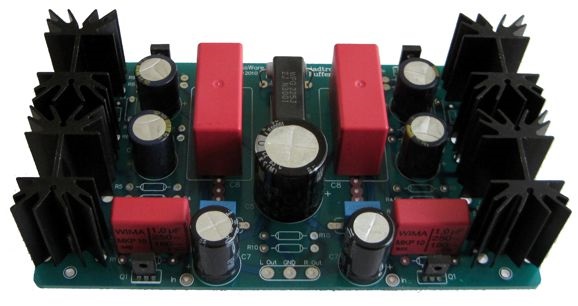
I quickly populated a Triadtron PCB so I could take a few photos. I left off the resistors, as carbon-film and metal-film resistor fans do not hear ear to ear on resistor choice. (I used carbon-film types, but with a tube-based signal source, I would have used metal-film.) Well, I have decided to sell off my remaining supply of Triadtron PCBs, as I am sure it is just what many who want to add a unity-gain power buffer for headphone listening to their existing tube gear will want. The USA-made, 2-oz copper, double-sidded, extra-thick PCB is 7 by 4 inches and the heatsinks are 1.5 inches tall. They only get quite warm, but never too hot to touch. Still, 400mA of total current consumption against the 24V B+ voltage results in 9.6W of heat. The big red capacitors are 10µF Wima polypropylene types, while the smaller red capacitors are 1µF in value and also Wima. The 10kµF center RC capacitor is a Nichicon audio-grade electrolytic shunted by a 2.2µF polypropylene capacitor. The schematic shows a polarized electrolytic 1kµF output coupling capacitor, but the kit includes a 50V non-polarized type from Nichicon. The 1kµF capacitors are Panasonic FC types. The PCB and the complete kits are available at the GlassWare store.
V8 Headphone Amplifier
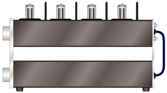
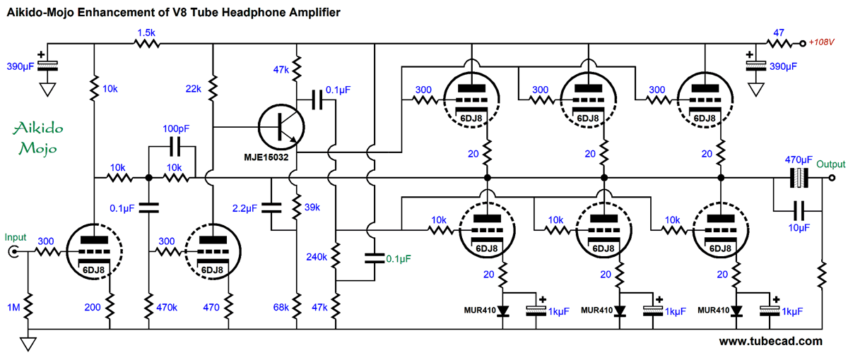
At the other extreme, an eight-tube OTL headphone amplifier could use noval tubes and require a much smaller enclosure. How small? Imagine a narrow but deep chassis, say 2-inches tall, 6-inches wide and 10-inches deep. The power supply would be external to the headphone amplifier, possibly in an identical chassis beneath the amplifier chassis. The push-pull output stage would hold six 6DJ8 tubes, thee per channel, thus 6 triodes per channel; now with this many triodes, driving low-impedance headphones becomes a possibility. Yes, this is a lot of tubes. The cost of eight new-production 6DJ8 tubes is about $128 USD, which may seem high, however, until you price NOS 6DJ8 tubes from the 1960s or one current-production 300B. (Another possible output tube type is the 6H30 or 5687 or ECC99.)
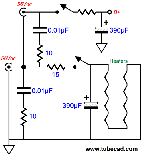
Well, my desire for this headphone amplifier remained dormant until I recently thought of an interesting cost-saving and space saving idea. The idea is simple enough: we use external power supplies, two 56Vdc desktop switching power supplies. Next, we add a two-stage on-off switch, so the first 56V power supply comes on and powers the eight tube heater elements in series, then the second power supply switches in and the B+ voltage climbs to 112Vdc, as the two 56Vdc output voltages are placed in series.
The 15-ohm resistor in series with the heater string drops the 56Vdc down to 50.4Vdc, which divided by 8 equals 6.3Vdc. In addition, the resistor forms an RC filter with the 390µF capacitor and slows the current inrush when the heaters are cold, thereby prolonging tube life. The 2k and 47-ohm resistors also create RC filters. Unlike the wall-voltage frequencies of either 50Hz or 60Hz, most switching power supplies scream at over 40kHz, which the RC low-pass filters will clean up nicely. The next step is to decide on the amplifier topology. I went searching through previous V8 designs of mine and I found one suitable after some slight modifications, as it was meant to be used with a B+ voltage of 200Vdc to 240Vdc.
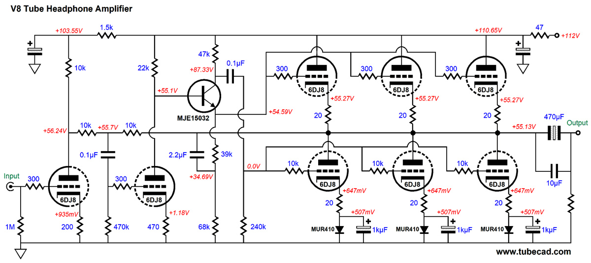
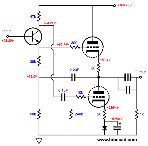
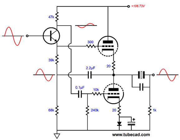
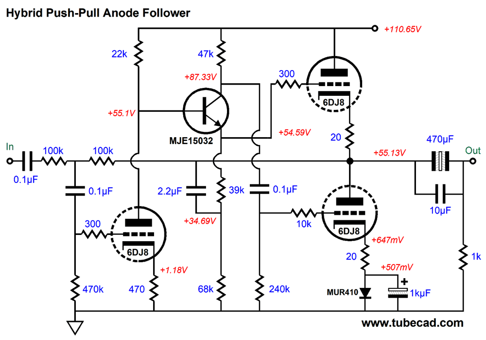
It's not as complicated as it might appear. The output stage is a simple totem-pole configuration with an NPN-transistor based split-load phase splitter providing equal output drive signals due to the 2.2µF capacitor returning the output stage's output signal to the phase splitter. Why not use another triode instead? We could, but the V8 would hold nine tubes. Moreover, the B+ voltage is just too low to successfully use a triode in the split-load phase splitter position. Here is the phase splitter and output stage.
The split-load phase splitter's load resistors may seem mismatched, but we must include the parallel resistance from the 240k grid resistor, which in parallel with the 47k resistor equals 39.3k of resistance.
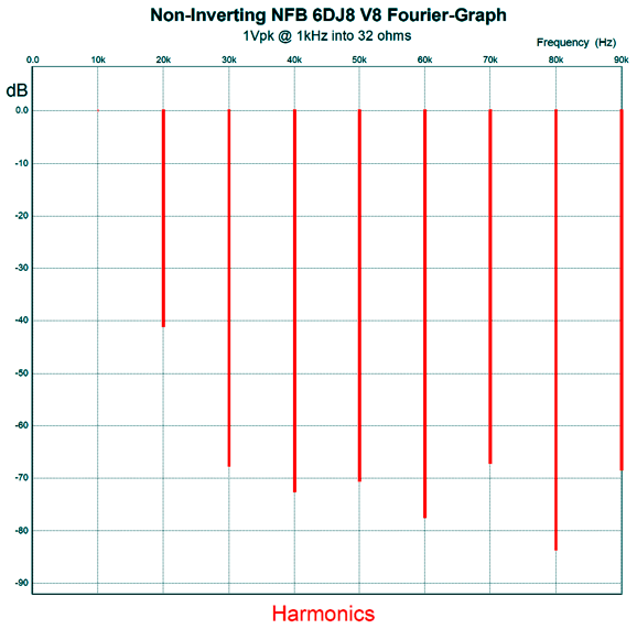
The bottom output triodes set the idle current through the output stage. Each triode gets its own 20-ohm cathode resistor and series MUR410G rectifier, which is bypassed by a large-valued capacitor. The total output stage idle current is about 20mA, which allows at least 1Vpk of class-A amplifier output voltage swing into a 32-ohm headphone driver. (Most smartphones and the iPod put out 1Vpk.) The amplifier's gain is 1:8.7 or about 19dB. With 1Vpk of input signal the output voltage swing is 8.7Vpk, which is 1.18W into 32-ohms, which is insanely too powerful for all but the least efficient planar headphones. In SPICE simulations, the THD was about 1% at full output and displayed a lovely single-ended strong second harmonic.
With 1Vpk of output signal into a 32-ohm load, the THD falls to about 0.1%, with an even lovelier cascade of harmonics.
Okay, returning to how this amplifier works, note that the bottom triodes each get a 10k grid-stopper resistor, while the top triodes only get 300-ohm resistors. Why the discrepancy? Positive-grid current. Once the grid becomes positive relative to the cathode, the grid defines a forward-biased diode with the cathode and current flows from the cathode to the grid. The grid current can charge the internal coupling capacitor to the bottom grids, which will result in a negative bias voltage on the grid until the capacitor discharges back to its idle voltage drop. If the increased capacitor voltage drop is great enough, the output tubes might cease conducting altogether. The 10k grid-stopper resistors prevent excessive capacitor charging by limiting the current flow. Since the top output triodes are DC coupled to the NPN transistor's emitter, there's no coupling capacitor to charge up. In general, with most music, extreme output voltage swings are rare and limited; nonetheless, the 10k resistors are worth using. The MUR410G rectifiers are needed due to the class-AB operation, wherein the peak current flow far exceeds the idle current. In other words, if we replace the rectifiers with 77.5-ohm resistors, when the output stage leaves its small window of class-A operation, from 0mA to 40mA, the capacitors shunting the resistors will charge up, which will result in too high a cathode voltage—possibly high enough to provoke "blocking" distortion, where the output stage briefly ceases to conduct any current and produces no output signal. In contrast, the rectifiers function as hard voltage references that limit the maximum voltage the shunting capacitors can charge up. The alternative would be to use fixed-bias with a negative-bias voltage of -0.505Vdc. In other words, the rectifiers allow us to get the same performance as fixed-bias, but without having to provide a negative power-supply rail voltage. The input stage consists of a simple grounded-cathode amplifier that delivers a gain of 1:15. The second stage is also a grounded-cathode amplifier that also yields a gain of about 1:15. In other words, the two stages together develop an open-loop gain of about 1:225. So how does the headphone amplifier's gain fall to 1:8.7? The second stage is configured with the output stage as an anode follower (aka plate follower), with a gain slightly below unity (1:0.82).
The negative feedback loop dramatically lowers the output stage's distortion and output impedance. For example, the output impedance absent the negative feedback comes in at about 22 ohms; with the negative feedback loop in place, 2 ohms. The downside to the anode follower circuit is that its input impedance is roughly equal to the first negative feedback resistor's value, which in this example is 10k. The input stage effectively sees this resistor in parallel with its own plate resistor, so the gain from the first stage drops to 1:10.5, which against the anode-follower gain of 0.82 gives us the final headphone amplifier gain of 1:8.7. If we wish to limit the high-frequency bandwidth from 8.5MHz to 160kHz, we can shunt the second 10k negative feedback resistor with a 100pF capacitor. Speaking of capacitors, we can inject some Aikido mojo with the addition of one tiny capacitor.
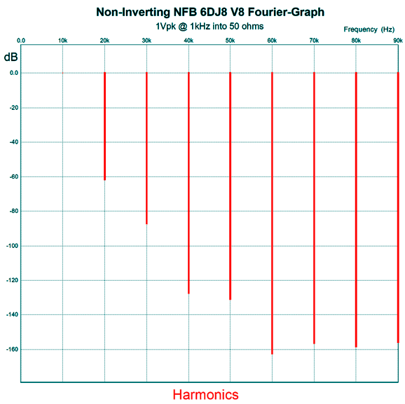
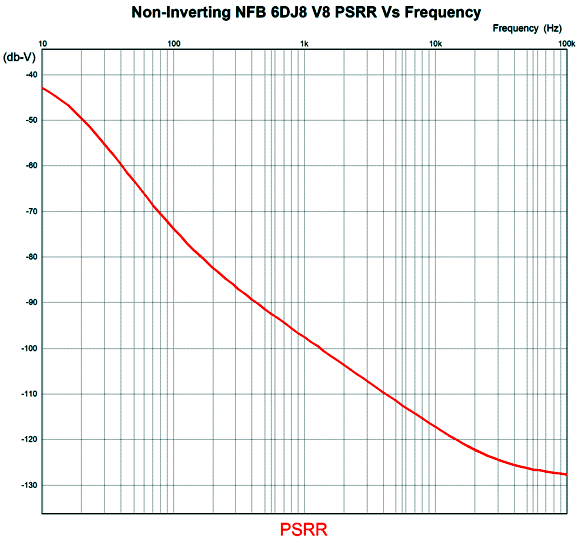
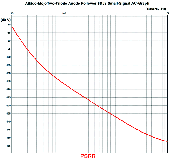
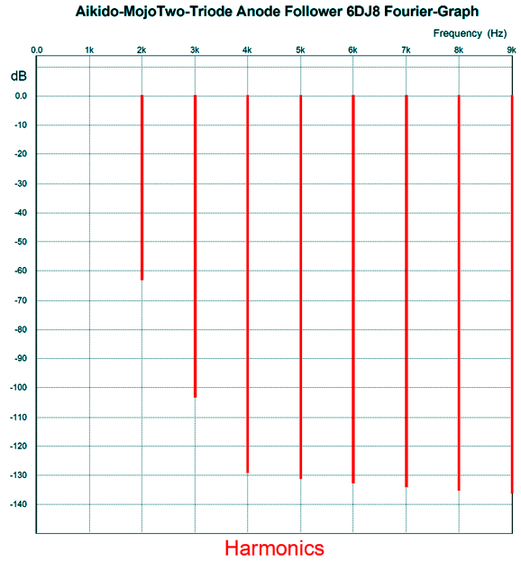
What the added capacitor does is relay 100% of the power-supply noise to the bottom of the 240k grid resistor, a resistor that is effectively in parallel with the 47k collector resistor. Thus, the top of the 47k resistor and the bottom of the 240k resistor will see the same 100% of the power-supply noise. What do their other ends see? About half (52%), while the NPN transistor's emitter puts out 48% of the power-supply noise, which is in phase. The result is that the output stage largely ignores the power-supply noise, as both top and bottom triodes modulate their current flow equally and in phase to the power-supply noise, thereby creating a power-supply-noise null at the output, which the SPICE generated graph below shows.
Normally, we look at either 100Hz or 120Hz, the ripple frequencies with 50Hz and 60Hz wall voltages. With a switcher power supply, the internal oscillator frequency falls somewhere between 40kHz to 100kHz; thus, the extended graph bandwidth.
So far, this V8 headphone amplifier seems quite intriguing, as it could power just about any dynamic headphone made and its two 56V switching power supplies cost only $30 to $40 or so for both! The two-stage turn on is a feature, as is the relatively small enclosure required. Although many will balk at the next feature, i.e. the output coupling capacitor, as I see it, an output coupling capacitor is a great feature, as it protects the fragile and expensive headphones from damage due to DC offsets or a shorted tube. (Some will foolishly try any noval tube they find, based on the assumption that all noval tubes are basically the same, in complete ignorance of the wild variety of noval tube types and differing pin-outs; for example, the 5687.) In addition, the relatively low B+ voltage and output-stage center voltage allows us to use a 470µF/63V non-polarized output coupling capacitor. (Ideally, it would be shunted with a large-valued film capacitor, say 10µF or more.)
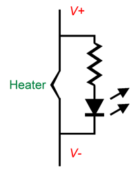
One possible liability is the dreaded Christmas-tree bulb problem. In other words, what if one of the 6DJ8 heater elements opens? How do we find it? The easy but irksome workaround is to test each 6DJ8 heater with an ohmmeter. The fancy workaround is to place in parallel with each heater element a red LED in series with a 3.3k resistor. Under normal operation, none of the LEDs will light, as insufficient current flows through the resistors; but when one heater opens, the other heater elements effective work as dead shorts and the bad 6DJ8's LED will light up. The math is simple: we subtract the LED's forward voltage drop (about 1.8V for red LEDs) from the power-supply voltage (56Vdc), divide the result by the threshold current (about 15mA), and get 3316 ohms, with 3.3k being close enough.
One aspect that I deem a feature others, no doubt, would view as a failing: the input triode is not included in the negative feedback loop. One global negative feedback loop that spans from input to output does result in the lowest distortion and the best PSRR. Furthermore, a global negative feedback loop could be implemented easily by returning some of the output signal to input triode's cathode. I strove to retain some single-ended flavor, however, so I like leaving the input triode out of the feedback loop. Building this V8 headphone amplifier pretty much requires a PCB, although point-to-point wiring would be possible. If I was going the point-to-point route, I would fabricate an inner sub plate made of aluminum, about 5 by 9 inches, with eight holes punched large enough to hold eight tube sockets. On this subassembly, I would wire up all the parts, and then I would suspend the inner panel within a larger enclosure with eight holes punched on the top to allow the tubes to protrude. The alternative of trying to use just the enclosure—without either a suspended metal plate or PCB—will result in much cursing, as the effort require would approach that needed to build a model ship within a bottle. In contrast, laying out the needed PCB would be a breeze. Indeed, I can "see" the arrangement in my mind's eye quite clearly, with the heater traces hugging the outside edges of the PCB, while the B+ voltage and ground travel down the center of the PCB, one atop the other with a double-sided PCB, with five mounting holes, the fifth hole falling at the exact center of the PCB. The tube sockets would attach to the top of the PCB and all the other parts would be soldered on the bottom side, as I definitely would want the eight tubes to protrude from the chassis top.
Aikido Mojo Anode Follower
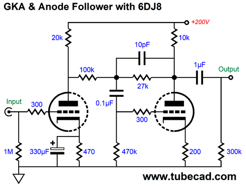
If we are willing to forgo some of the constant-current-draw feature, we can inject some Aikido mojo that dramatically improves the PSRR and reduces the output impedance.
The gain is set to 1:6 (15.7dB). The bypassed cathode resistor on the input triode both increases its gain and PSRR. The 100k and 27k negative feedback resistors decrease the anode follower's gain and result in a power-supply noise null at the output. How this works is that the first stage leaks 15.2% of the power-supply noise at its plate, which the anode follower tries to invert at its plate, but the power-supply noise pulls in the opposite direction, resulting in a power-supply-noise null. If the second triode offered higher or lower transconductance, the null would not occur with these negative feedback resistor values. (The 330µF and 0.1µF capacitor values are Aikido-mojo related, so should not be replaced with whatever you find in your parts box.) At 100Hz, the PSRR is -67dB. If we add an RC filter made from a 1k resistor and 470µF capacitor (and bump up the B+ voltage to 215Vdc), the PSRR falls to -116dB. Plenty low, in other words.
The THD in SPICE simulations was about 0.1%, mostly 2nd-harmonic, at 1Vpk into a 20k load.
What 's not to like here?
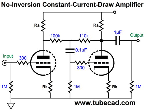
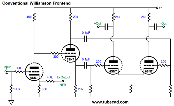
Frontend for Push-Pull Output Stage
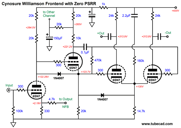
Here is my cleaner version:
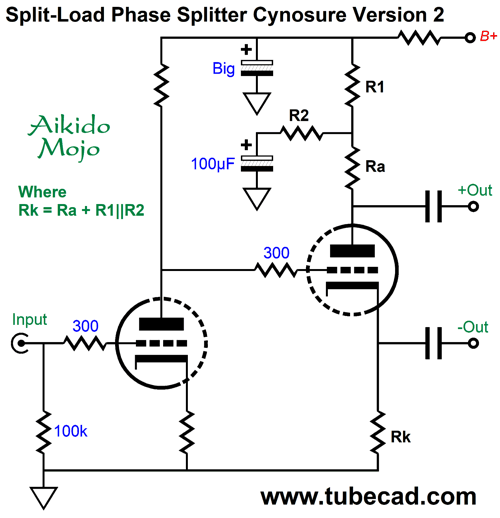
True, the long tail isn't very long, which is why replacing the shared cathode resistor with a constant-current source (CCS) is a good idea—if we can get away with it; i.e. if there is enough of a voltage drop to allow the CCS device to function.. Well, I finally got around to drawing the new schematic and running some SPICE simulations on the design. Let us start with the new Cynosure split-load phase splitter, version two.
Your grandfather would not understand what is going on here. The goal is to see an equal amount of in-phase power-supply noise leak from each output, as the following push-pull stage will treat the noise as a common-mode signal.
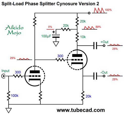
In this example, the input stage's PSRR is -12dB, so 25% of the B+ voltage ripple appears at its plate. With the cynosure configuration, both phase outputs deliver 25% of the noise in phase with each other. With a textbook split-load phase splitter, the bottom output would put out 25%, while the top output would put out 75%. Here is a fleshed out example with the 6SN7.
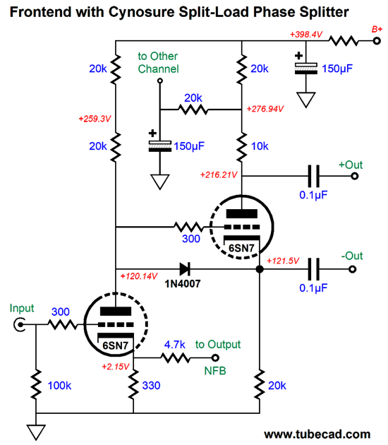
The next step is to add a long-tailed differential amplifier.
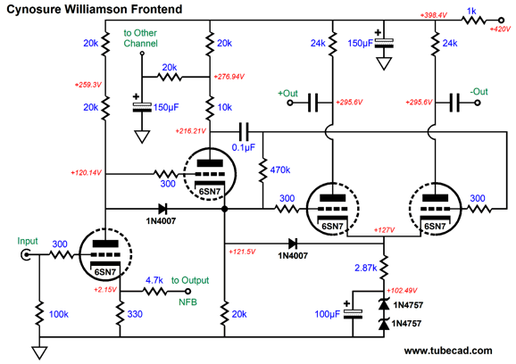
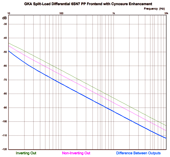
The two 1N4757 diodes are 51V zeners that are there to soak voltage and provide a low impedance, which the 100µF further lowers. The 2.87k cathode resistor forces a power-supply-noise null at the differential amplifier's plates. The way this works is that the equal amount of in-phase power-supply noise at each grid becomes imposed upon the shared cathode resistor, creating an anti-phase current swing against the B+ voltage noise. The 4.7k negative feedback loop resistor sets a gain of only 1:15. If higher gain is needed, say 1:32, which would deliver 64W with 1Vpk of input signal and an 8-ohm load. In this case, we would use 316-ohm and 10k negative feedback resistors. In both the cases, the two resistors in parallel equal 308-ohms, which the 6SN7 needs in this configuration to make the cynosure resistor values work. How well does the circuit work? Here is the PSRR versus frequency graph.
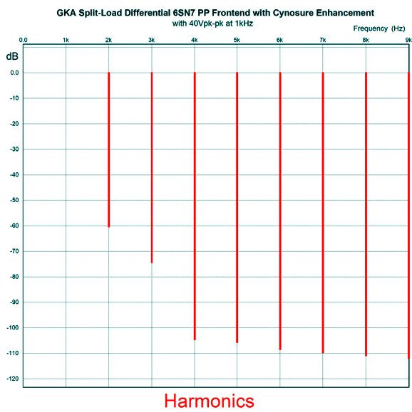
Better than -70dB at 100Hz, which is not bad at all. Assuming the push-pull output stage offers a fair to great balanced canceling of the common-mode noise, the final PSRR with the feedback loop in place can be over -100dB. Open-loop, the gain of the front-end circuit is 1:200 (+46dB). With 40Vpk-to-pk output, the THD is about 0.1% and offers a lovely single-ended cascade of higher harmonics.
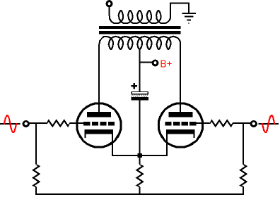
This front-end could easily drive a pair of EL34 or KT88 or KT120 output tubes. Since I can never cease seeing new variations in a circuit's topology, here is a final variation that is designed to to deliver a PSRR of zero. Good God why? An Ultrapath push-pull output stage.
In this output stage, the cathode bypass capacitor terminates into the B+ voltage, not ground. In other words, the cathode will see 100% of the B+ ripple; thus, the grids must also see 100% of the ripple, or the ripple will become signal to be amplified.
The zeners are gone and the 160k resistor and 2.2µF capacitor inject enough ripple to produce zero PSRR. In short, the output stage cannot "see" any of the B+ ripple, as the plate, grid, and cathodes all see the same amount of ripple, just as the coffee in you cup and your lap cannot "see" the 400MPH the airplane within which you sit travels.
Music Recommendation: Not Music
Our ability to hear is a miracle. I have the odd ability to hear single conversation within a crowded restaurant. On Pentecost Sunday in church, where twenty to thirty read the text in twenty to thirty different languages, I can selectively hear one voice above the cacophony, such as the minister's, who usually is the furthest away from me. How is that possible? Imagine a computer trying to make out just one voice in thirty. We humans are amazing.
//JRB
Patreon
User Guides for GlassWare Software
For those of you who still have old computers running Windows XP (32-bit) or any other Windows 32-bit OS, I have setup the download availability of my old old standards: Tube CAD, SE Amp CAD, and Audio Gadgets. The downloads are at the GlassWare-Yahoo store and the price is only $9.95 for each program. http://glass-ware.stores.yahoo.net/adsoffromgla.html So many have asked that I had to do it. WARNING: THESE THREE PROGRAMS WILL NOT RUN UNDER VISTA 64-Bit or WINDOWS 7, 8, and 10 if the OS is not 32-bit or if the OS is 64-bit. I do plan on remaking all of these programs into 64-bit versions, but it will be a huge ordeal, as programming requires vast chunks of noise-free time, something very rare with children running about. Ideally, I would love to come out with versions that run on iPads and Android-OS tablets.
|
I know that some readers wish to avoid Patreon, so here is a PayPal donate button instead. Thanks. John Broskie
John Gives
Special Thanks to the Special 89
I am truly stunned and appreciative of their support. In addition I want to thank the following patrons:
All of your support makes a big difference. I would love to arrive at the point where creating my posts was my top priority of the day, not something that I have to steal time from other obligations to do. The more support I get, the higher up these posts move up in deserving attention.
If you have been reading my posts, you know that my lifetime goal is reaching post number one thousand. I have 447 more to go. My second goal is to gather 100 patrons. I have 16 patrons to go. Help me get there.
Only $9.95
The Tube CAD Journal's first companion program, TCJ Filter Design lets you design a filter or crossover (passive, OpAmp or tube) without having to check out thick textbooks from the library and without having to breakout the scientific calculator. This program's goal is to provide a quick and easy display not only of the frequency response, but also of the resistor and capacitor values for a passive and active filters and crossovers. TCJ Filter Design is easy to use, but not lightweight, holding over 60 different filter topologies and up to four filter alignments: While the program's main concern is active filters, solid-state and tube, it also does passive filters. In fact, it can be used to calculate passive crossovers for use with speakers by entering 8 ohms as the terminating resistance. Click on the image below to see the full screen capture.
Tube crossovers are a major part of this program; both buffered and un-buffered tube based filters along with mono-polar and bipolar power supply topologies are covered. Available on a CD-ROM and a downloadable version (4 Megabytes). Download or CD ROM
|
|||


| www.tubecad.com Copyright © 1999-2021 GlassWare All Rights Reserved |