| John Broskie's Guide to Tube Circuit Analysis & Design |
21 November 2020 Post Number 520
No-Gain, No Pain Revisited
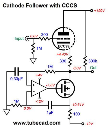
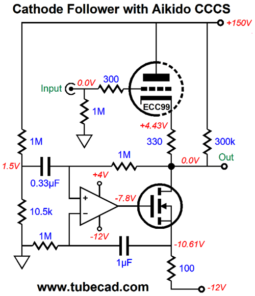
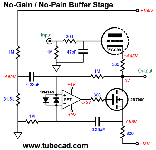
DC coupled from input to output, this is not your father's tube circuit. The OpAmp strives to achieve two goals: no DC offset at the output and an idle current flow equal to the triode's. In other words, the OpAmp and MOSFET define a compliant-constant-current source (CCCS) that presents a high-impedance, but not a fixed current flow. If the ECC99 were replaced with a 12BH7 or 12AU7 or 5963, the CCCS will match the change in idle current flow through the triode. Indeed, as the ECC99 ages, the CCCS will also match its declining conduction. In that same post, I showed an Aikido version, which undoes the cathode follower's leaking of some B+ voltage ripple at its cathode. How much ripple leaks?
It depends on the triode. The formula for a a cathode follower's PSRR with a constant-current source loading of its cathode is: PSRR = 20Log(1/mu) With a 12AX7, we get a PSRR of -40dB; with a 6SN7, -26dB. Of course, if there's no B+ voltage ripple due to high-voltage regulation, then the need for the Aikido mojo version is diminished. Nonetheless, even with a high-voltage regulator, I would build the Aikido version from that post:
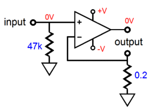
The first thing I noticed was that the OpAmp needs input protection diodes, as at startup, the DC servo caps will need time to charge up, which until they do will force a large voltage differential between the OpAmp's inverting and non-inverting inputs; a no-no. With two protection diodes in place, the inputs can never move more than 0.7V apart. In SPICE simulations, the frequency plotline peaked above 1MHz, which a 47pF capacitor quelled nicely.
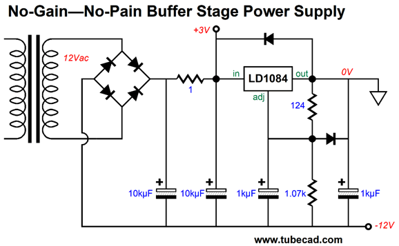
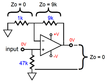
The second item I noticed was the assumption that a truly clean negative power-supply rail would be available. Of course, it would be regulated, but how good are three-pin adjustable voltage regulators? It depends. If they are used only to power ICs, they are probably quiet enough. (Most OpAmps offer a poorer PSRR from their negative power-supply rail than their positive. I have seen high-end Japanese audio gear that doubled the capacitance on the negative power-supply rail to compensate.) But in this application, the additional assumption was that the negative power-supply rail would also power the tube's heater element, which draws 400mA at 12V. In other words, the negative power supply can use an upgrade. Here is the upgraded power supply design.
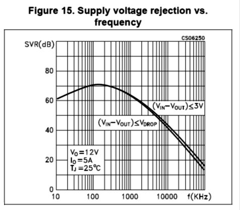
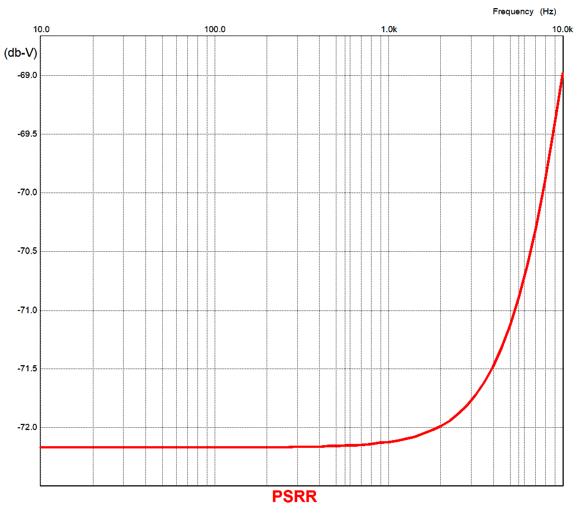
The big difference between the original power supply from post 491 and its revision is the added input pre-filter in the form of an RC filter. I love regulator pre-filters. I have used them mostly in high-voltage regulators and I have found that they make a huge difference in the high-voltage regulator's reliability—if for no other reason than that the RC resistor acts as a fuse. Moreover, the RC filter scrubs away high-frequency rectification hash. In low-voltage IC regulators, the RC pre-filter seems to lend a more high-end sound to solid-state gear, sounding as if you had an extra $1,000 to spend on better equipment. Why would that be so, other than self-delusion? Let's look at a high-quality 5A LDO (low-dropout regulator) IC, the LD1084. This IC regulator has been optimized to provide excellent PSRR at 120Hz, which is the ripple frequency here in The States.
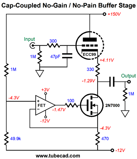
Considering the 5A current draw, the better than -70dB PSRR figure is impressive. Note, however, that its PSRR falls off above 120Hz. The RC pre-filter comes into play here. For example, a 1-ohm RC resistor and a 10kµF RC capacitor define a low-pass filter at 16Hz, which offers increasing attenuation above 16Hz. Here is a remaining big problem: no output coupling capacitor. "Wait a minute," you think, "that's the circuit's best feature."Is it? True, a big high-quality coupling capacitor can cost over $100 each. But also consider the cost of repairing your solid-state power amplifier or replacing your loudspeaker woofers. At startup, the output will slam to the negative power-supply rail until the DC servo capacitors charge up. The same will happen if the ECC99 is jiggled in its socket. Here is the punch line: I would only use this DC-coupled unity-gain buffer with a tube-based power amplifier. Failing that, I would add a voltage window comparator and relay, the latter only opening when the buffer stage has settled down and no DC offset appears at its output. Here is a safer, capacitor-coupled version.
The same Aikido mojo obtains, but the loading as moved away from being a CCCS to just CCS. In other words, the OpAmp and MOSFET establish a fixed current flow, not a compliant one. Although the output sees a coupling capacitor, the OpAmp doesn't, as it DC couples to both the B+ and -12V power-supply rail.
The result of doing away with the DC servo capacitors is amazing PSRR down to DC.
1st-Order Crossovers Remember, a tweeter sees signal at all the frequencies a recording holds, differing only in level. For example, if we crossover a tweeter at 3kHz with a 1st-order crossover, the tweeter's incoming signal will be 20dB down at 300Hz, which translates into 10% of the amplifier's output voltage. In contrast, a 3rd-order crossover provides -18dB of attenuation per octave below the crossover frequency, 60dB per decade. Thus, with the same 3kHz crossover frequency, a 3rd-order crossover delivers only 0.1% of the amplifier's output voltage swing into the tweeter at 300Hz. For example, if the recording prompts 100W of power at 300Hz, the 8-ohm tweeter will see 4Vpk at 300Hz with a 1st-order crossover (1W), but only 0.04Vpk at 300Hz with a 3rd-order crossover (0.0001W).
On the other hand, if you are running a flea-power, feedback-free, tube amplifier that puts out only 8Vpk (4W into 8-ohm loads), you can probably easily get away with a 1st-order crossover. On the other-other hand, if you are running a solid-state flea-power amplifier, watch out. Since just about every solid-state power amplifier employs gobs of negative feedback, when the small solid-state amplifier clips, which it will all the time, its clipped sinewaves become square-waves, which pack huge amounts of high-frequency energy. Thus, the paradox of small 20W solid-state power amplifiers burning out more tweeters than 200W amplifiers. So far, I have assumed only two-way loudspeaker crossovers, but things become far more interesting with more crossover frequencies, as they allow us to create crossover cascades.
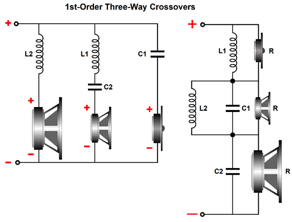
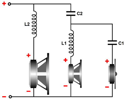
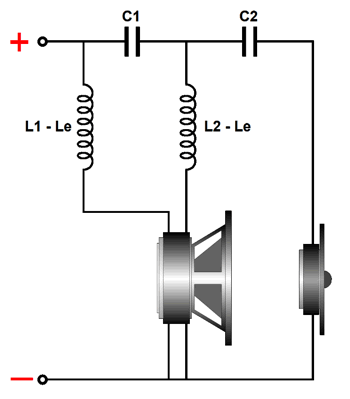
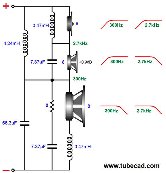
We start with a three-way loudspeaker and two crossover frequencies, say 300Hz (F1) and 2.7kHz (F2). We could give each its own separate crossover filter, a low-pass 300hz filter for the woofer, a band-pass 300hz-to-2.7k filter for the midrange, and a high-pass 2.7kHz filter for the tweeter.
The crossover on the left is a parallel type; the one on the right, a series type. Both yield the same crossover slopes and use the same valued capacitors and inductors—if and only if the amplifier driving the loudspeaker on the left is a current-out type, not a voltage-out design, which 99.9999% of all stereo amplifiers are; and if and only the speaker on the right is driven by a voltage-out amplifier. With a voltage-out power amplifier, the three-way 1st-order parallel math falls apart, as we never achieve the potential of ruler-flat frequency response.
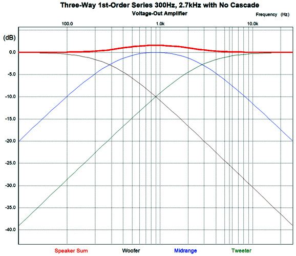
The closer the two crossover points are, the worse the results. For example, with crossover frequencies of 200Hz and 6kHz, the errors would prove mild; but with crossover frequencies of 1kHz and 3kHz, we can expect big discrepancies from ruler flat. With a current-out power amplifier, the three-way 1st-order parallel crossover's three drivers sum to flat frequency response, but the impedance dips in the midrange, which works in our favor, as the drop in impedance undoes the bump in frequency response.
In contrast, with a current-out power amplifier, the three-way 1st-order series crossover shown above produces a bump in the impedance plot in the midrange, and, thus, a bump in the frequency response.
In an effort to make things work with 1st-order parallel three-way crossover and voltage-out amplifiers, many fudge factors have been tried, but the results are never very promising. The usual explanation is that the reactive components (the capacitors and inductors) in a passive parallel three-way crossover interact with each other, causing imbalances. That is not the actual cause, however, as a three-way active crossover with three power amplifiers, each driving a single driver, also produce the same departure from flat, yet the amplifiers drive no reactive components other than the speaker drivers themselves.
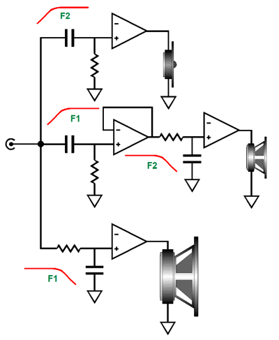
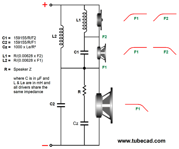
The true issue is that the 1st-order parallel crossover's perfect summing and phase-flat output only obtains with a two-way crossover. On the other hand, we can cascade a pair (or more) of two-way crossovers, so that each cascaded crossover receives exactly what it needs to sum to flat. For example in the following parallel design, the tweeter sees a -6dB-per-octave rolloff below 2.7kHz and a -12dB-per-octave rolloff below 300Hz.
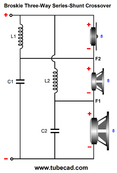
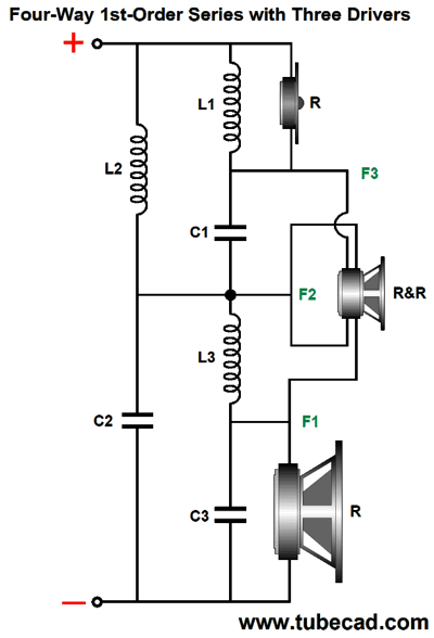
Here is the series version.
The crossover cascade results in the tweeter being down by 38.7dB at 100Hz, rather than the -28.7dB offered by the non-cascaded crossover, a more than threefold reduction in AC voltage.
Another way to look at it is a fourfold decrease in the likelihood of burning out the tweeter. (At 10Hz, the cascaded crossover plotline is down -78dB, while the single 1st-order plotline is down only -48dB, which equals 31 times more signal.) Okay, why not use 1st-order crossover slopes on the woofer and midrange and use 2nd-order or 3rd-order slopes on the tweeter? Actually, that is exactly what some (if not many) commercially made loudspeaker systems do. The crossover component values are jiggled about until something approaching a flat frequency plotline is achieved. If the tweeter's crossover frequency is high enough, for example, above 5kHz, this approach isn't that bad. But at lower crossover frequencies, where the ear is most sensitive to phase aberrations, the garbled phase response damages the signal's integrity. Okay, here is a way-outside-the-box idea: what if we used a woofer with two 8-ohm voice-coils (DVC) and tweeter in place of the woofer-midrange-tweeter combo.
Assuming the woofer offers wide bandwidth, both the frequency and phase plots would be the same as the true three-way. In other words, this is a sneaky way to preserve the 1st-order's perfect phase response with the added safety of the cascaded slopes for the tweeter. In fact, we could use the two-voice-coil driver to test the sonic signature of different crossover alignments, as the two 8-ohm voice-coils attach to the same cone, so the same frequency and phase response obtains for both. We could use only one voice-coil driven fullrange as the reference, and then switch to a two-way crossover under test. Other than the 1st-order crossover, the results would no doubt prove dumbfounding. I would use either a jazz saxophone solo or a single voice singing a capella as the test track. If the power amplifier is a voltage-out type, which as I mentioned previously 99.9999% of all stereo amplifiers are, the 1st-order series crossover proves best. See post 481 for more details. Here is the math behind the 1st-order, three-way cascade crossover.
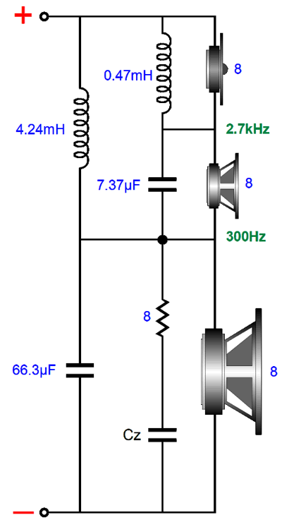
Note that the woofer is shunted by a resistor in series with a capacitor. This RC circuit is known as either a "Zobel network" or an "impedance-compensation network" or a "conjugate network." It undoes the woofer's own intrinsic voice-coil inductance. No doubt, you have seen that all woofers display rising impedance with frequency, starting at some midrange frequency, say between 300Hz to 1kHz. This increase in impedance is the result of voice-coil inductance's reactance. By shunting the woofer with a countervailing resistance and reactance, the capacitance and inductance cancel, creating a flat impedance plotline. In addition to the issue of tweeter safety, we must consider the other weak-link in a three-way loudspeaker: the woofer. Where tweeters are quick but fragile, woofers are robust but sluggish. If it were not for the mangled phase and complexity, the ideal crossover would be a 4th-order or 5th-order or 6th-order…, as we want to limit the woofer's upper frequency response as much as possible. (Do not believe me? Just play a fullrange signal into a subwoofer.) Ideally, we want a 1st-oder crossover that cascades crossovers for both the woofer and tweeter outputs. Alas, this is impossible with a three-way loudspeaker. Or is it? My workaround was the series-shunt crossover shown in post 473. This crossover is also phase-flat, but it does result in a small dip in impedance in the middle frequencies.
My older workaround was to impose an additional low-pass filter tuned to the tweeter's crossover frequency on the woofer.
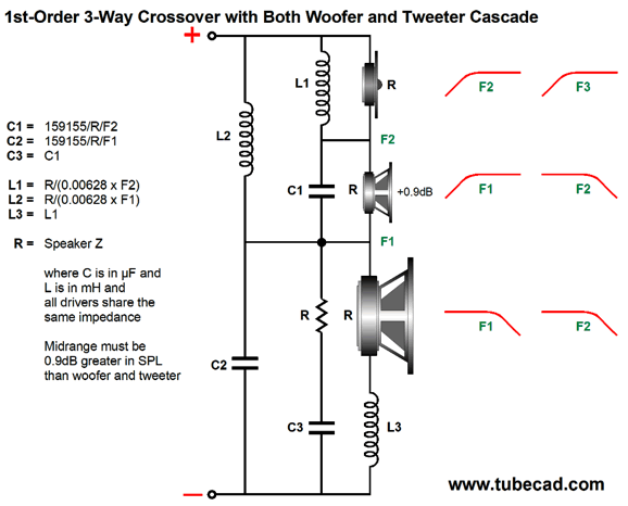
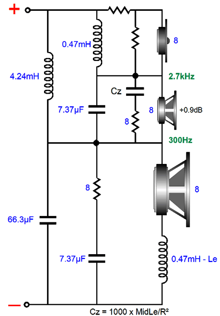
Yes, it looks as though a Zobel network and another inductor were added. But in this arrangement, the extra capacitor (C3) is tuned to the tweeter's crossover frequency, not to the woofer's inductance. The result of adding this extra low-pass filter is that the woofer's output not only falls more steeply at high-frequencies, but is slightly down in the midrange, which creates a slight dip in frequency response. The workaround is to make the midrange slightly higher in SPL than the woofer and tweeter, by 0.9dB. Let's look at an example.
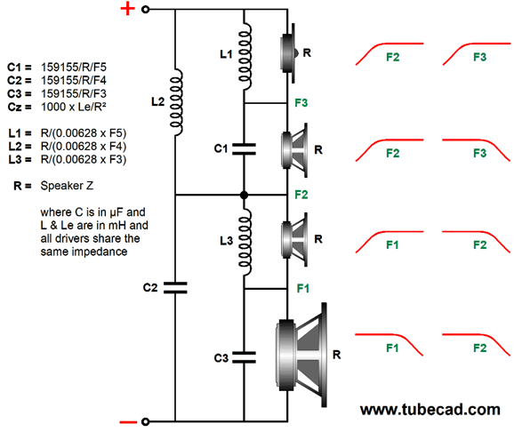
The crossover frequencies are 300Hz and 2.7kHz. The midrange puts out 0.9dB more SPL than the woofer and tweeter. The capacitor and inductor values used in the crossover between midrange and tweeter are used again on the woofer—except, not quite. We can subtract the woofer's inductance (Le) from the inductor L3's value.
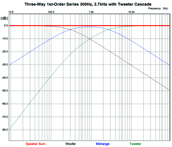
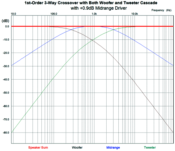
I added a Zobel network to the midrange driver. (In fact, tweeters often benefit from using a Zobel network, with the exception of planar and ribbon tweeters that present almost no inductance.) Here are the frequency plots for this crossover.
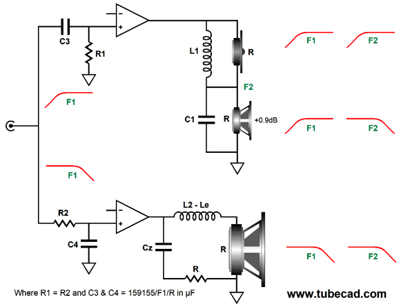
Only the midrange sees -6dB-per-octave leading and trailing crossover slopes. Both woofer and tweeter see slopes that begin as -6dB-per-octave then increase to -12dB-per-octave. The important detail here is that the midrange must offer an SPL 0.9dB more efficient than both the woofer and the tweeter. Most often, however, the midrange need only be 0.9dB greater than the woofer, as most tweeters are so much more efficient that they require a two-resistor voltage divider to bring down their SPL to match the other drivers. The padding network on the tweeter presents the same impedance to the crossover as the tweeter does. For example, a -6db pad would consist of an 8-ohm resistor shunting an 8-ohm tweeter, with a 4-ohm series resistor, resulting in an 8-ohm load. While we are at it, we could easily bi-amp with the three-way design while retaining the woofer and tweeter cascade. The important detail to remember is that the midrange must offer 0.9dB more efficiency than the tweeter. (I am assuming that each amplifier holds a volume adjustment, so we needn't worry too much about the woofer's efficiency.)
The first crossover frequency (F1) defines the split between the two amplifiers, and then each amplifier drives a crossover. Why not just place an additional low-pass filter in front of the bottom power amplifier, so that amplifier can drive the woofer directly? We could, but we would probably need to add a Zobel network anyway, so we might as do things right from the beginning. In this arrangement, the woofer's own intrinsic series inductance is used as part of its low-pass filter; and the Zobel network flattens the woofer's impedance plotline. What about the added DRC from the inductor, wouldn't it ruin the amplifier's damping factor? For the most part, damping factor is grotesquely overrated. Do not forget that the loudspeaker driver's own DC resistance is effectively in series with the amplifier's output impedance, so it little matters if we add 0.2 ohms of inductor DCR. In addition, inductor L2 is small in value, as it is tuned to a relatively high frequency, F2. In fact, it is possible that the woofer's inductance (Le) is sufficient by itself.
Four-Way 1st-Order Crossovers
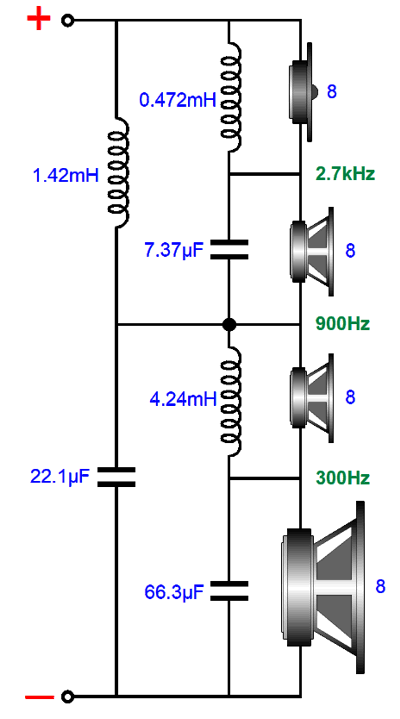
Here is a design example:
I did not include Zobel networks for both the woofer and midranges, but they should be used. Note that I drew both middle drivers the same size. This was not an accident. Think about it: using two identical midrange/fullrange drivers makes a lot of sense. Most music is found in the midrange frequencies, say between 300hz and 3kHz. Yes, we all love crystal high-frequencies and thumping bass, but the human voice and most expressive musical instruments, such as the cello and saxophone, reside in the midrange. Having two identical midrange drivers ensures that the both the frequency and phase response will be identical. True, we won't get the added power handling of using a larger midrange-woofer with a smaller midrange driver, but the added purity has to be worth the trade. In addition, the two smaller midrange centers can be closer together, helping the two blend together.
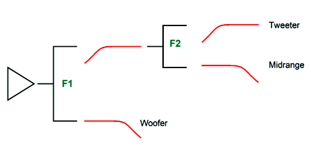
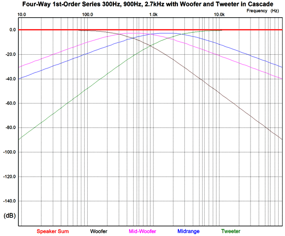
The woofer and tweeter see progressively steep rolloffs, which will also contribute to a cleaner and safer sound. Drawing the flowchart of cascading crossovers helps us see the frequency divisions better.
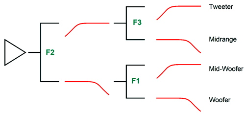
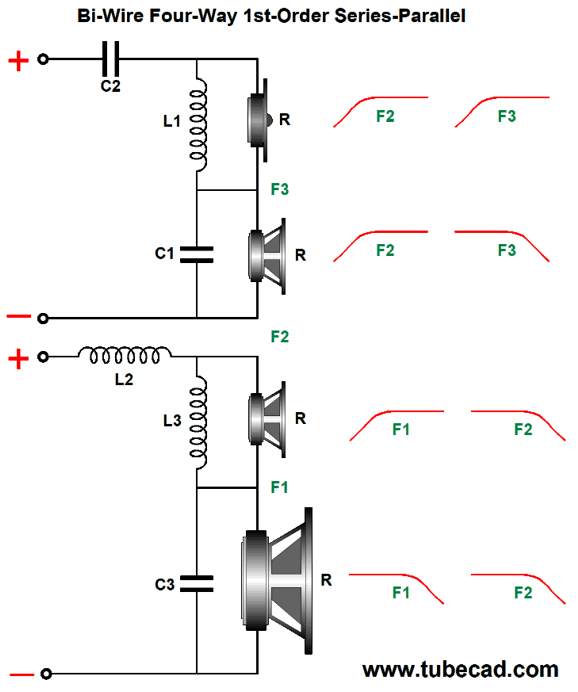
The power amplifier effectively drives a two-way crossover at 900Hz that then drives two additional two-way crossovers, one at 300Hz and the other at 2.7kHz. If we wanted the most tweeter protection possible, we would start with a two-way crossover at 300Hz that then drives a two-way crossover at 900Hz and then a 2.7kHz crossover, so the tweeter begins with a 1st-order slope, then moves on to a 2nd-order slope, and then ends with a 3rd-order slope at the lowest frequencies. Or, we could just place the crossover to the tweeter at a higher frequency, say 4kHz. For example, using the crossover cascade that favored both the woofer and tweeter with progressively steeper slopes, we could use 250Hz, 1kHz, and 4kHz as crossover frequencies. Since the range between 250Hz and 4kHz is so wide (four octaves), I would begrudgingly opt for a larger midrange-woofer and a smaller midrange, say a 6-inch midrange-woofer and a 4-inch midrange. The four-way crossover lends itself to a bi-wire arrangement.
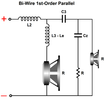
This crossover combines series with parallel configurations. Alternatively, we could go pure-parallel with the woofer and mid-woofer.
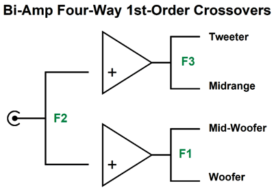
The advantage here is that the woofer's own inductance becomes a useful part of the crossover. While we are at it, we could easily bi-amp with the four-way design.
The center crossover frequency (F2) defines the split between the two amplifiers, and then each amplifier drives a passive two-way crossover. Okay, let's do some more way-out-of-the-box thinking. In the section devoted to three-way crossovers, I mentioned dual-voice-coil (DVC) woofers. Most DVC drivers are subwoofers or ceiling speakers. Of course, nothing other than cost prevents us from having custom-made DVC fullrange drivers fabricated. With such a driver, we could build a four-way loudspeaker that used three drivers.
The DVC fullrange sees 1st-order slopes throughout, while the woofer and tweeter see initially a 1st-order slope, and then a 2nd-order slope. The result is flat frequency and phase plotlines. Imagine someone opening up such a loudspeaker and trying to figure out why crossover seemingly holds unneeded parts. Okay, now imagine if I were a patent attorney! At the end of the year, I would own at least 365 patents; at the end of a decade, least 3,650 patents.
Five-Way Crossovers
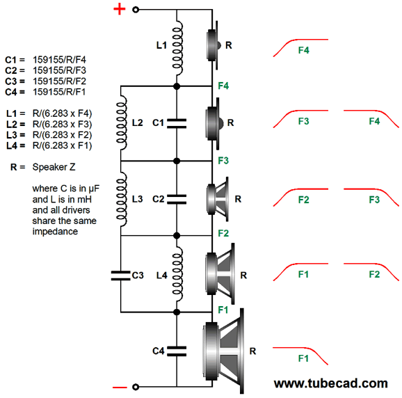
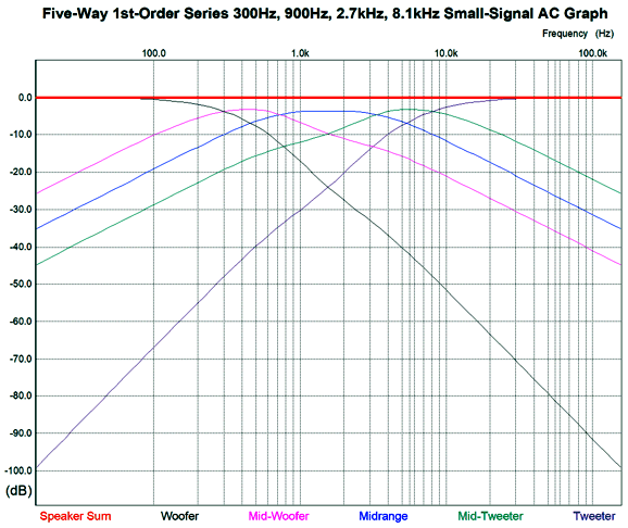
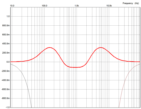
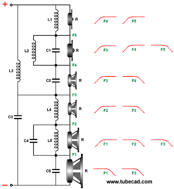
This is a simple 1st-order five-way series crossover that delivers to each driver -6dB-per-octave slopes. Here is the corresponding graph.
Note that not all the slopes are true -6dB-per-octave slopes. For example, note how the tweeter's slope starts out -20dB per decade, but then undergoes a slight boost at 300Hz, and then continues at 6dB-per-octave. Okay, now let's look at the alternative that cascades crossover frequencies.
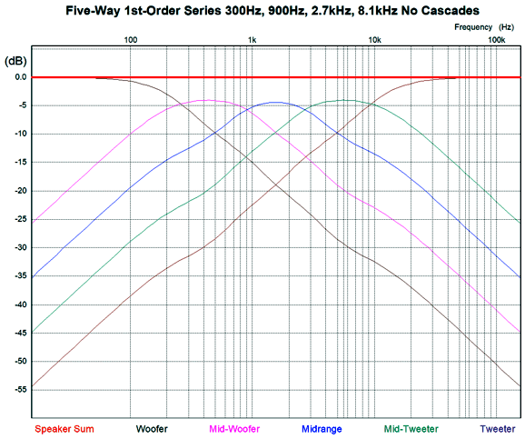
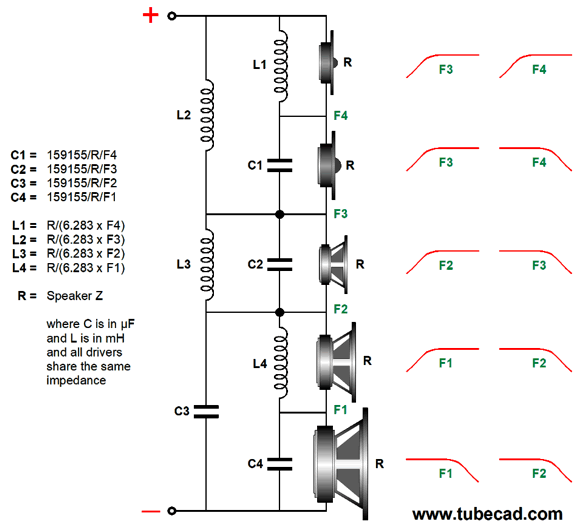
The following graph shows how the woofer and tweeter see progressively steeper crossover slopes.
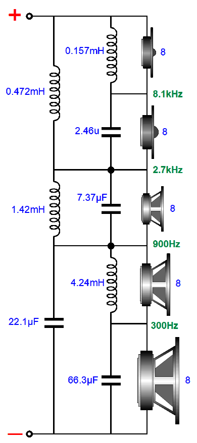
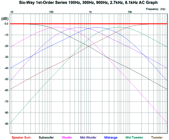
Note how the exact same number of reactive parts (capacitors and inductors) are used, but are differently arranged. Also note that the tweeter is only -38dB down at 100Hz in the previous graph; then, compare the attenuation in the graph immediately above. Here is an example crossover with crossover frequencies of 100Hz, 300Hz, 900Hz, 2.7kHz, and 8.1kHz.
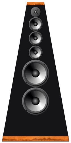
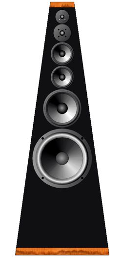
Most readers will imagine using a 12-inch woofer, an 8-inch midrange-woofer, a 6-inch midrange, a 5-inch midrange-tweeter, and 1-inch tweeter. In contrast, I would use two 4-ohm 8-inch woofers in series, and three identical 5-inch fullrange drivers, and one 1-inch tweeter. Why? Increased clarity and better blending of all the drivers due to closer spacing and the three identical 5-inch fullrange drivers sharing identical frequency and phase responses; in addition, a narrower cabinet could be made, which also helps.
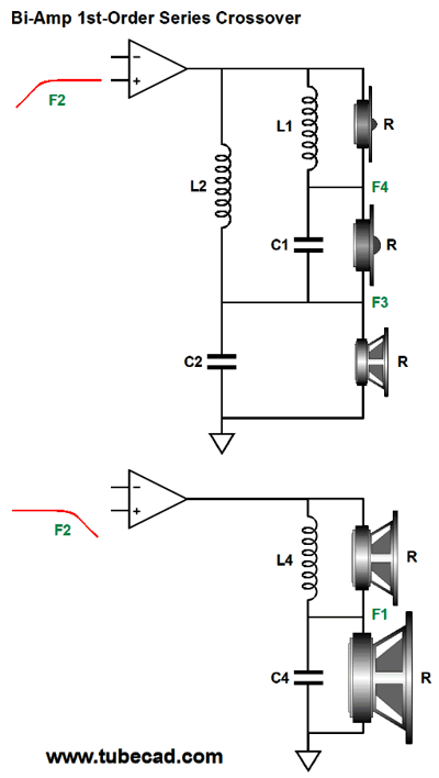
If we want to bi-amp, we would apply the second crossover frequency F2 between amplifiers.
The woofer still sees cascading slopes, as does the tweeter.
Six-Way Crossovers
In addition, I have always wanted to try a 0.5-inch dome tweeter, and crossing over at 8.1kHz makes this possible. Either a 1.2-inch tweeter or a 2-inch dome midrange could be used as the mid-tweeter. In fact, Morel make a driver that holds both a 1-inch tweeter and a 2-inch dome midrange on one and the same faceplate and in close spacing between the two, the TweeMid TM 4055-8.
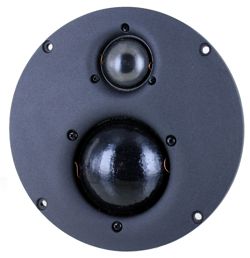
One of the most amazing loudspeakers I have ever heard was a home-built tiny two-way that held a 6-inch woofer and 2-inch dome midrange. The bass fell off below 80Hz and the highs drooped beyond 12kHz, yet the loudspeaker sounded supremely balanced. Unless the speaker was directly compared to a wider bandwidth loudspeaker, its frequency omissions were not apparent. Equally balanced lows and highs makes the difference, whether there is less or more of each, as long as they are equally there or equally not there.
When you talk on the phone to a friend, do you have any problem recognizing the voice? It seems amazing that we have no problem, as the telephone's lower and upper frequency response is severely truncated, reproducing only frequencies from about 350Hz to 3.5kHz. There is an old formula that states that the square root of the product of the highest frequency a loudspeaker can produce against its lowest frequency should equal 1000, a formula that this little wonder complied with, sounding neither bass shy nor highs weak. I am sure that if the tiny gem of a speaker were used either with a big subwoofer or with a super-tweeter, the balance would be lost; but it would sound fantastic with both a subwoofer and super-tweeter.
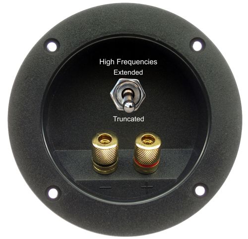
I asked its creator how he had come to make his optimal design choice. His answer was that he had not; he hated the all-too-popular 3kHz crossovers due to the crossover frequency being too close to the ear's inner canal resonance, thus he used a 3rd-order 2kHz crossover and 1-inch dome tweeter; but after burning up his second tweeter, he decided to use the 2-inch dome midranges instead of the fragile tweeters. Happily, the results were ear pleasing. Had the tweeters survived, the loudspeakers would certainly have sounded overly bright and bass thin. The clever workaround would have been to add a toggle switch to the speaker cabinet, with the top position allowing the 1-inch tweeter full high-frequency bandwidth for use with a subwoofer; but with the switch in the down position, a 12kHz low-pass filter for standalone operation would engage.
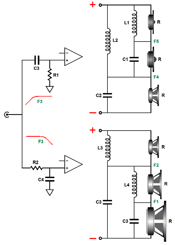
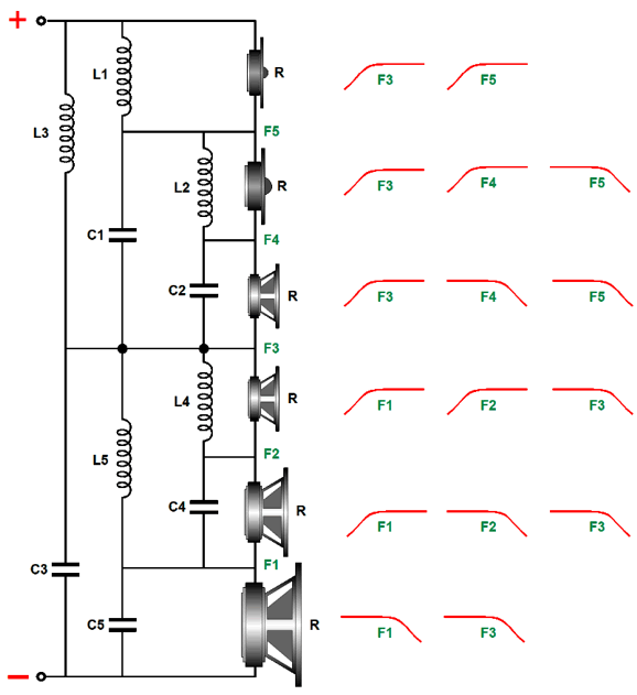
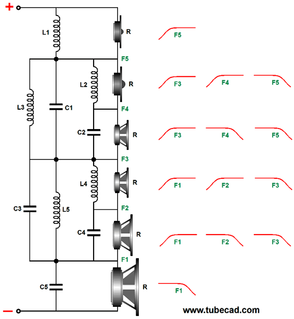
(I believe all high-end loudspeakers should provide a switch that selects for either a low-output-impedance solid-state amplifiers or higher-output-impedance tube-based power amplifiers.) Okay back to six-way crossovers, we can multiple cascade both towards the woofer and the tweeter by making a split at the center crossover frequency (F3).
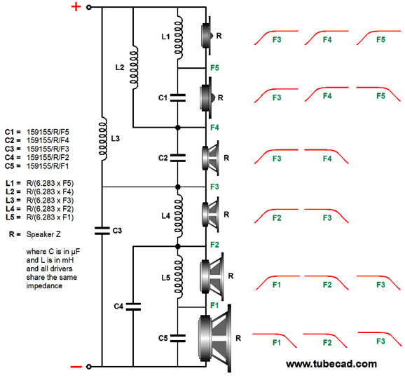
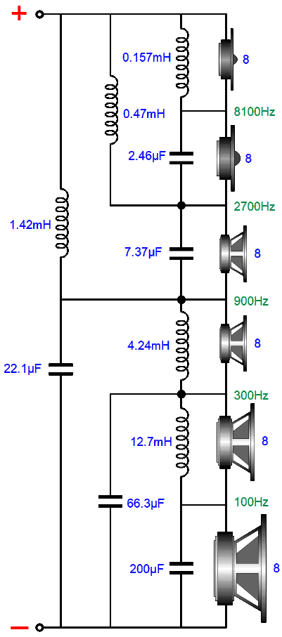
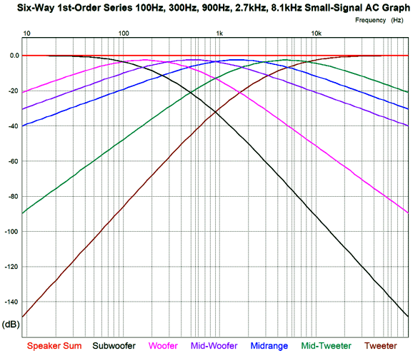
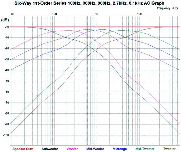
Here is an example crossover.
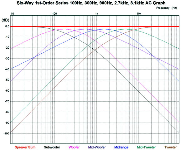
And here are its plotlines.
I particularly like the ultimate -18dB-per-octave slopes for both the subwoofer and tweeter, with the woofer and mid-tweeter transitioning into -12dB-per-octave slopes, while the midrange-woofer and midrange see pure 1st-order slopes, as these two drivers define the heart of the loudspeaker. This six-way crossover is also tube-amplifier-friendly. What does that mean?
We divide the world into the tall and the short, the thin and the fat, the smart and the simpleminded, but most fall into the middle. Well, many tube power amplifiers, especially single-ended amplifiers without a negative-feedback loop, fall into the middle between voltage-out and current-out amplifiers. Many tube-based power amplifier sport output impedances as high as 2 to 4 ohms. This high an output impedance can provoke big changes in a loudspeaker's frequency response, depending on the drivers and the crossover topology. Well, this six-way crossover still delivers a flat frequency plot with a 4-ohm output impedance. In short, this is my favorite six-way topology, but many others are possible. For example, let's look at an alternative arrangement.
This topology is not tube or current-out amplifier friendly, as it assumes a low output impedance.
With an output impedance of zero ohms, we get a perfectly flat frequency plotline. Add just 1-ohm of series resistance, and we end up with this plotline:
It's possible that is just what some audiophile wants, but it isn't flat. The following topology is tube or current-out amplifier friendly, and it presents a constant load equal to the driver's impedance.
The plotlines are interesting, as the subwoofer, woofer, mid-tweeter, and tweeter eventually see 2nd-order slopes.
One last variation, which is not tube or current-out amplifier friendly and which fails to present a flat impedance. Furthermore the subwoofer and tweeter see only 1st-order slopes. So why bother? If the subwoofer's frequency response extends high enough and if the tweeter is robust enough, the steeper slopes on the woofer and mid-tweeter might prove compelling.
And here is its graph.
Such a loudspeaker might work well with digital playback but falter with LPs. Why? Warped records can produce subsonic signals. There is no conclusion here other than speakers are much more difficult to design than most imagine. The drivers present neither a flat impedance nor frequency response. Capacitor tolerances are loose. Inductors present unwanted DCR and can interact with each other due to mutual coupling. Cabinets bend and flex with bass notes. The room's walls, floor, and ceiling reflect sound. It's a mess. Having more options, however, can only help.
Music Recommendation: Individually Twisted
The group's name is a joke takeoff on the Art Blakey jazz group, Jazz Messengers. Many famous musicians and singers have played with the Jazz Passengers, such as Jeff Buckley, Elvis Costello, Deborah Harry, Bob Dorough, Jimmy Scott, Mavis Staples, and Tom Waits. On Individually Twisted, Deborah Harry sings on eight of the twelve tracks. I find her performance on the song that Jimmy Scott sung in their In Love album fascinating, An Imitation of a Kiss, as I thought Scott's cover of that song was definitive, but Harry acquitted herself handsomely. By the way, if you don't know Jimmy Scott (aka Little Jimmy Scott), you should, as his voice is unnaturally high due to Kallmann syndrome and his phrasing is simply fantastic.
//JRB
User Guides for GlassWare Software
For those of you who still have old computers running Windows XP (32-bit) or any other Windows 32-bit OS, I have setup the download availability of my old old standards: Tube CAD, SE Amp CAD, and Audio Gadgets. The downloads are at the GlassWare-Yahoo store and the price is only $9.95 for each program. http://glass-ware.stores.yahoo.net/adsoffromgla.html So many have asked that I had to do it. WARNING: THESE THREE PROGRAMS WILL NOT RUN UNDER VISTA 64-Bit or WINDOWS 7, 8, and 10 if not 32-bit or any other 64-bit OS. I do plan on remaking all of these programs into 64-bit versions, but it will be a huge ordeal, as programming requires vast chunks of noise-free time, something very rare with children running about. Ideally, I would love to come out with versions that run on iPads and Android-OS tablets.
|
I know that some readers wish to avoid Patreon, so here is a PayPal button instead. Thanks. John Broskie
John Gives
Special Thanks to the Special 90 To all my patrons, all 90 of them, thank you all again. I want to especially thank
I am truly stunned and appreciative of their support. In addition I want to thank the following patrons:
All of your support makes a big difference. I would love to arrive at the point where creating my posts was my top priority of the day, not something that I have to steal time from other obligations to do. The more support I get, the higher up these posts move up in deserving attention.
If you have been reading my posts, you know that my lifetime goal is reaching post number one thousand. I have 480 more to go. My second goal was to gather 1,000 patrons. Well, that no longer seems possible to me, so I will shoot for a mighty 100 instead. Thus, I have 10 patrons to go. Help me get there.
Support the Tube CAD Journal & get an extremely powerful push-pull tube-amplifier simulator for TCJ Push-Pull Calculator
TCJ PPC Version 2 Improvements Rebuilt simulation engine *User definable
Download or CD ROM For more information, please visit our Web site : To purchase, please visit our Yahoo Store: |
|||


| www.tubecad.com Copyright © 1999-2020 GlassWare All Rights Reserved |