| John Broskie's Guide to Tube Circuit Analysis & Design |
|
09 January 2018 Post 408
Single-Ended Amplifiers They have no choice but to run in strict class-A and to idle on the sweet-spot of the plate curves. I remember what it was like hearing a single-ended amplifier from the 1940s being played with high-end audio gear in the 1980s: Something must be wrong; it doesn't sound bad. No, it didn't sound bad; in fact, it sounded so good that I marveled at how little progress had been made in the 50 years since its creation. (I had a similar feeling when I saw a picture of my maternal grandfather as a young man, who was about 23 in the 70 year-old black-and-white photo. "Something must be wrong; he doesn't look old," I thought. It wasn't just his young handsome face, but the photo didn't look old; indeed, it could have been taken from a current issue of GQ magazine. His hair short and he wore a black crew sweater. He looked entirely contemporary, unlike the picture of my fraternal grandfather from the same era, early 1900s, which betrayed the funky old haircuts and clothes and stilted posing for the camera look. Instead, my maternal grandfather looked like he must have owned a time machine and the photo was taken on one of his visits into the past. What made this altogether odder was that he died in his mid twenties and I never knew him; and that I was almost twice as old as he was in the photo as I gazed upon it.) Single-ended amplifiers might prove weak in watts, but they seldom prove week in making music come alive. Expect much more on this topic this year.
Split-Load Phase Splitter as SE OPS
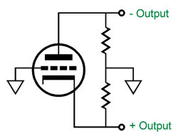
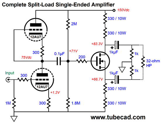
It may not look possible, but this single-tube output stage offers a gain of almost two (+6dB) and a relatively low output impedance. Both features appear paradoxical, but the last attribute seems the least likely to many. Why? Because we have all been told that the split-load phase splitter presents asymmetrical output impedances at its two outputs, with the bottom output offering low impedance and the top output presenting staggeringly high impedance. This is true enough, but only relative to ground, but not output to output. in other words, a load impedance bridging the two output sees a low output impedance, roughly equal to twice what a textbook cathode follower would deliver.
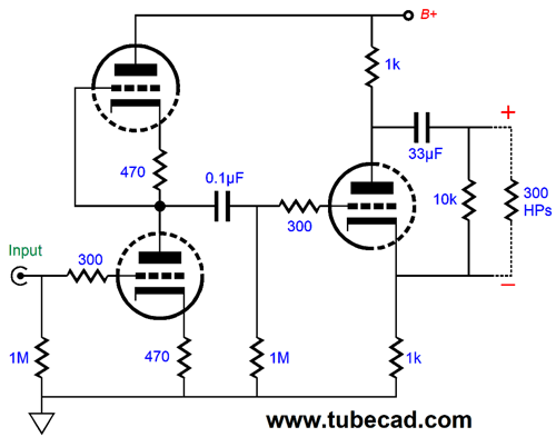
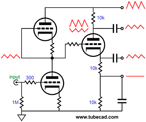
All of this was covered back in post 167, which is definitely worth rereading. The PSRR depends on the triode used, but in general, it's not great. Workarounds exist, however, as shown in the schematic below, which shows a complete headphone amplifier for 300-ohm headphones, such as the famous Sennheiser models. (Speaking of Sennheiser, if you haven't checked out their all-out assault on electrostatic headphones and its accompanying amplifier, the HE-1, which places the class-A driving MOSFETs within the headphone cups, so the cable capacitance doesn't become part of the load. Here is the link to their patent.)
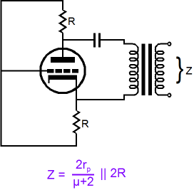
This Aikido-esque design makes use of the first stage proving both signal gain and a PSRR of -6dB (50% reduction of power-supply noise at its output). It is easy to see why some voltage gain would prove useful, but who would deem such a poor PSRR desirable? We would. This is an example of two half a wrongs making a right. The key to understanding this power-supply-noise-null trick is to ignore ground. That's right, just pretend it doesn't exist. Why? The headphone driver never sees ground and is supremely indifferent to it; what it does care about supremely is the differential signal across its leads—nothing else. Relative to ground, both outputs are polluted by 50% of the B+ ripple, but the headphone driver does not attach to ground. How did we get the split-load phase splitter's top output to leak the same amount of power-supply noise as the bottom output? Here is a schematic from post 231, which is also worth checking out.
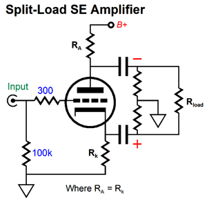
The first stage delivered 50% of the power-supply noise to the output triode's grid, which caused its cathode to follow the grid, which in turn created a varying current flow through the cathode resistor, a varying flow that travels up through the plate resistor, which being the same value as the cathode resistor causes the same signal to be impressed across the plate resistor, but in inverted phase. The result is that the 100% of power-supply noise combines with -50% of the noise, which yields zero. That is the theory; reality differs slightly, as no triode ever offers infinite transconductance. Thus, we must make the plate resistor slightly larger in value than the cathode resistor to make up for the slightly less than 50% of power-supply noise at the cathode.
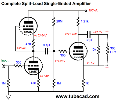
In the schematic above, note that the plate resistor is much bigger in value than the cathode resistor and that we added a 20M resistor. The added resistor allows us to use larger valued cathode and plate resistors, which allows for bigger output swings. Speaking output swings, this output stage is a pure class-A, single-ended affair, as no pushing and pulling obtains, even though it offers a balanced output. This means that the peak output voltage swing is never more than the product of idle current against the load impedance. In other words, if you desire more output power, then you will have to pay with higher idle current and, due to the higher current, higher heat dissipation at idle. Moreover, as this single-ended, class-A amplifier is resistively loaded, not inductively or constant-current source loaded, the maximum theoretical efficiency is only tad over 8%, which assumes perfect, lossless output devices, which the triode falls short of being. Well, other than glossy ads in audio magazines, no one ever said class-A operation was cheap. On the other hand, the great thing about single-ended operation is that it is smooth—it may bend, but the bending is smoothly done, with no sharp kinks. One way to get away with running a higher idle current is to use a beefier output tube, say a triode-connected KT88.
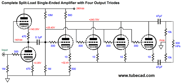
In terms of appearance, nothing beats a big power output tube. But what cannot be seen is transconductance, which is the key attribute in any power amplifier. A tiny EL84 offers roughly the same transconductance as the big KT88 (about 11mA/V) and a single ECC99 triode develops almost the same amount of transconductance 9.5mA/V with a plate voltage of 150V and 18mA of current flow. Thus, if we use both triodes within the ECC99's glass envelope, we yield far more transconductance than a single KT88. Alternatively, we could use four lower-power triodes in parallel.
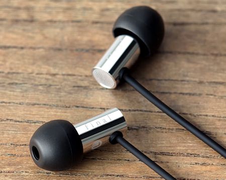
Each triode gets its own 10-ohm cathode resistor to prevent current hogging, but all share the common cathode resistor below and the plate resistor above. Note that two 47µF coupling capacitors are used, rather than the one used before. Why? Danger. In the single-ECC99 version, both outputs held a DC offset of 22.5V, which wouldn't bother the headphone driver, as differentially, the equal voltages equal zero volts across the driver's voicecoil. But what if the wires fray and the sheathing break open, revealing the wire inside? Although it seems unlikely that anyone would find a way to get shocked, but then they say that Murphy was an optimist. I have been enjoying listening to my Final E3000 earbuds.
Unlike big massive headphones that ride atop one's ears, these small metal cylinders rest inside the ear, which is enough to make me nervous about the 22.5V DC present on both outputs. With the two coupling capacitors, there is no danger. Having said that, who knows: maybe the DC voltage would lend some polarized-wire mojo to the sound; in any case, I would only try it with all plastic headphone structures. Speaking of putting high voltage in your ears, Sennheiser has a patent for an electrostatic earbud that is worth checking out.
Normal, over-the-ears electrostatic headphones see huge AC voltage swings and contain a DC bias voltage of up to 540Vdc. But this bias voltage is in series with a 20M resistor, so even if you got shocked, it would be unpleasant, but you wouldn't die. In the 22.5Vdc example, no series resistor limits the current flow. As they say: it's not the voltage that kills you, it's the current. Be warned.
Of course, if we seek transconductance, then we should look for solid-state output devices, such as MOSFETs and bipolar transistors, as they offer screaming transconductance in comparison to tubes.
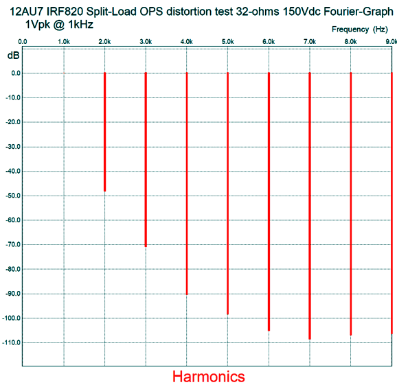
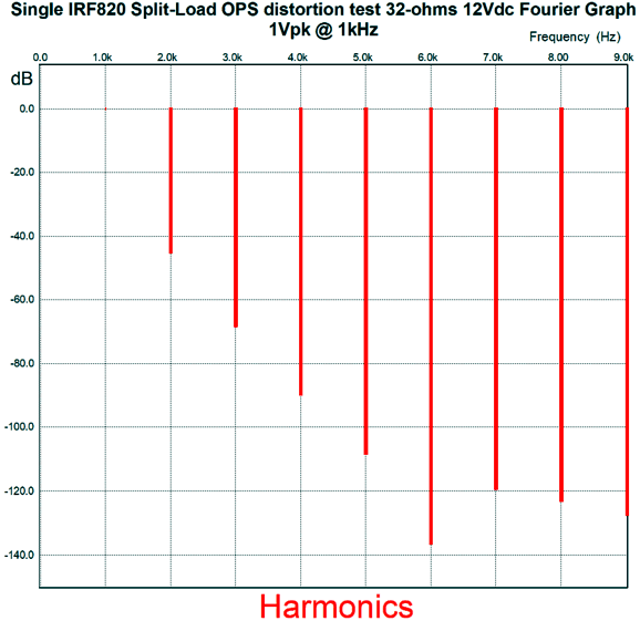
Note that the drain resistor is the same value a the source resistor, which is a testament to how high the MOSFET's transconductance is, as the power-supply-noise still obtains. Here is the SPICE-generated Fourier graph for the above circuit.
The problem with this circuit is that although the power MOSFET need only swing a few volts to make the headphones thunder, the MOSFET and its drain and source resistors must displace the entire B+ voltage of 150V. Assuming an idle current of 100mA, this results in 15W of heat dissipation from the split-load phase splitter at idle. That's a lot of wasted power to develop only 0.15W into a 32-ohm headphone driver—double this for stereo listening. In other words, we went from 8.33% theoretical efficiency down to 1% actual efficiency. By the way, I am sure that some readers wonder why I didn't just direct couple the first state to the output stage, as the MOSFET's high turn-on voltage would buy us the needed voltage headroom to drive headphones.
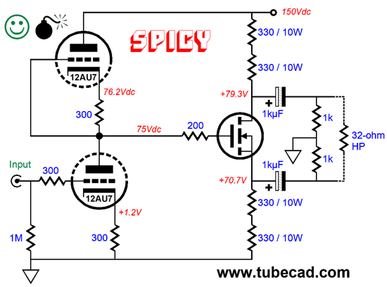
This circuit works perfectly in SPICE, but what will happen in the real world? Possibly, one channel will sound just fantastic, while the other channel barely makes any sound. What went wrong? The good channel was lucky enough to have the input stage's two triodes so closely matched that the B+ voltage was exactly halved (or slightly lower than half); the weak channel was not so lucky, as the voltage break occurred at 80Vdc, which starved the MOSFET of useable voltage. Tube makers, in the old days, only sought a 5% to 10% match on the twin triode tubes such as the 12AX7 and 6SN7; and with non-audio tubes, such as the 6BX7, seemingly no attempt was made to ensure matched triodes. One workaround to the problem of low efficiency is to use a far lower B+ voltage for the MOSFET.
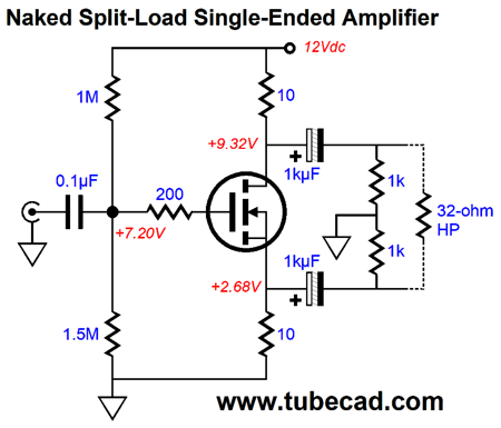
This split-load phase splitter is "naked," by which I mean that it relies upon a line-stage amplifier or MP3 player's or DAC's output to provide the needed signal gain. At the same time, low-ohmage headphones do not require big voltage swings to roar and the MOSFET-based split-load phase splitter amplifier offers a gain close to 2. In other words, a Chromecast-Audio puck and this simple headphone amplifier would play plenty loud. Since no Aikido mojo obtains, a regulated 12V power supply should be used. At 1Vpk into 32-ohms at 1kHz, the distortion is a little better than 1%, but it does follow a lovely single-ended profile.
One way to retain triode sonic glory with MOSFET brute force is to go Super-Triode, wherein the triode drive the solid-state device that does all the hard work of driving the low-impedance load.
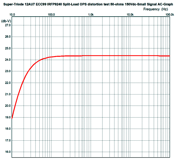
The triode's current conduction varies almost not at all, as very little gate-voltage swing is needed to make the MOSFET swing big currents. The triode draws 10.5mA, while the MOSFET draws 95mA. The MOSFET is a TO-247 packaged IRFP9240, which is a -200V / 150W power MOSFET that cost less than $3 each. My first thought was that 40W MOSFET would prove better due to its much lower input capacitance, but SPICE simulations showed -3dB high-frequency droop at 2MHz, with less than 1 degree of phase shift at 20kHz. (In fact, I would place a low-pass filter at the input that limited the bandwidth to 100kHz or so.)
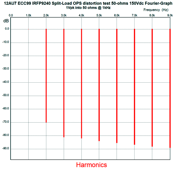
The intended load impedance is 50 ohms, which explains the 200µF coupling capacitor. We can buy 100µF film capacitors for not that much money, as Audyn makes a tubular 400V 100µF polypropylene capacitor for less than $25 each at PartsExpress.com and Panasonic makes a rectangular 500V 100µF capacitor that costs $20 at Mouser.com. Of course, we could use electrolytic capacitors bypassed with quality film capacitors. One problem with electrolytic capacitors—other than their being icky—is leakage current. Ideally, no DC current flows through a capacitor, but electrolytic capacitors are not ideal, as they do leak a tiny trickle current, which can cause a distressing pop when the headphones are plugged into the jack. The workaround is to use a jack that shorts the output to ground when no headphone plug is inserted. The distortion at 1Vpk is below 0.1%, as the following graph shows.
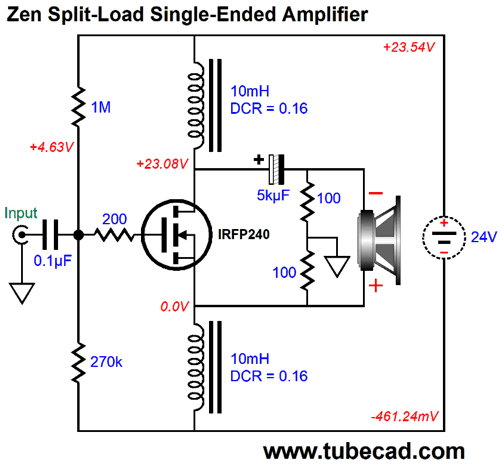
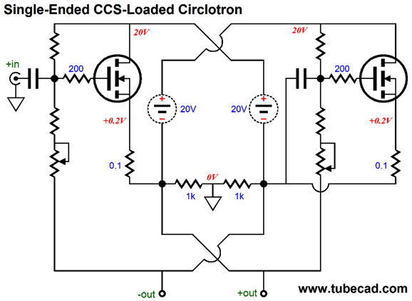
Headphones! Is headphone amplifiers all that you ever think of? No, in fact. But they do make a good starting point. By the way, I have encountered plenty of audiophiles with the attitude that loudspeakers are for real men and headphones are for sissies. An interesting notion, particularly as the average die-hard speaker lover is 64 years old, while the average die-hard headphone lover is 24; throw both in an elevator with the stipulation that only one can exit alive, and I would place my bet on the headphone lover. If we wish to drive loudspeakers, the 8-ohm types, then the split-load phase splitter is not going to do us much good—well, at it's not if entirely tube-based or not transformer-coupled. Once we do add an output transformer, however, the input signal must climb to huge swings due to the low gain of less than two the split-load phase splitter offers. In contrast, if we switch to solid-state output devices, then a low-power split-load phase splitter amplifier could be made. Here is an example. Very Zen, no? What is the sound of one MOSFET powering a circlotron amplifier? This would provide the answer. I have shown more traditional-looking single-ended circlotron amplifiers before, but both amplifiers are functionally the same, as in same gain, same distortion, same output impedance.
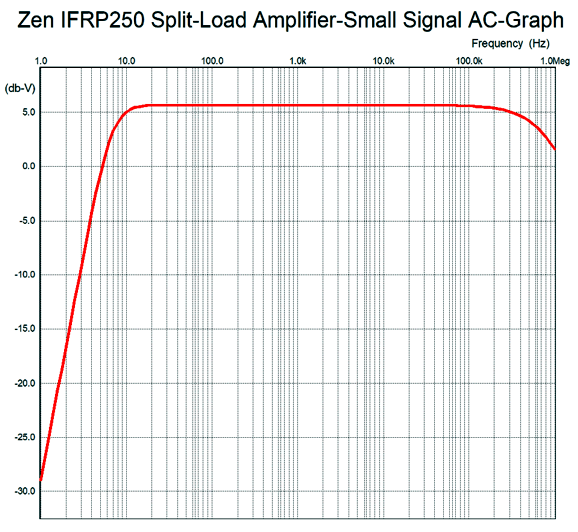
They differ in that the inductor-loaded design is far more efficient. Remember, that the theoretical limit to constant-current-source-loaded a single-ended amplifier's efficiency is 25%, assuming ideal devices and 50% for inductively-loaded equivalent amplifiers. In terms of cost, the inductor-based design probably wins, as huge heatsinks cost a bundle, not that low-DCR inductors (chokes) are cheap, but Hammond makes a 10mA inductor with a DCR of only 0.16 ohms, which is excellent, as this design only works as long as the DCR is low, which rules out air-core inductors. (One possibility would be a dual-winding inductor wound about an audio transformer core; a 1:1 isolation transformer, in other words.) Each channel must get its own floating power supply, which could be a 24V/4A switcher desktop design. A line-stage amplifier capable of swing 10Vpk of clean signal is required to drive the split-load phase splitter amplifier to full output. (To keep the MOSFET from over heating, two or more might have to be placed in parallel, each with its own 0.1-ohm source resistor.) This amplifier puts out peak voltage swings of 20V, which translates into 25W into an 8-ohm load. In SPICE simulations, the performance was quite good. Here is the frequency bandwidth plot.
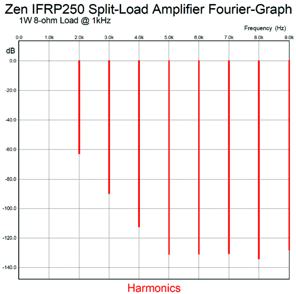
Next, the Fourier graph for 1W at 1kHz into 8 ohms.
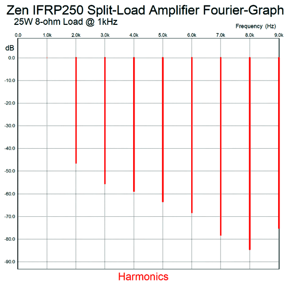
Lovely, just lovely. Now, 25W at 1kHz.
Not as lovely as before, but still not bad. To put this in perspective: a 300B-based single-ended amplifier would be thrilled to have this harmonic structure at full output; but then, no single 300B-based single-ended amplifier could put out 25W.
Special Thanks to the Special 60 (lost one) Only those who have produced a technical white paper or written an article on electronics know just how much time and effort is required to produce one of my posts, as novel circuits must be created, SPICE simulations must be run, schematics must be drawn, and thousands of words must be written.
If you have been reading my posts, you know that my lifetime goal is reaching post number one thousand. I have 592 more to go. My second goal is to gather 1,000 patrons. I have 940 patrons to go.
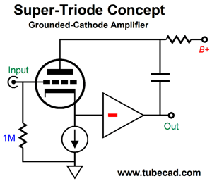
Super-Triode Amplifier
It may look startlingly different from most amplifiers, but more than half of it is pure, stodgy, everyday practice; this half:
We see the output stat (the OPS) and the voltage-amplification stage (the VAS), and what is missing is the long-tail differential input stage with a fancy current mirror loading. Put all that together and you have the generic solid-state power amplifier. Even replacing the VAS's constant-current source with a triode circuit only slightly modifies the design, as a triode-based constant-current source is still a constant-current source. Where the amplifier radically departs from the norm is the use of the input triode as the negative feedback mechanism.
A quick recap: for an amplifier to count as a super-triode design it must meet three requirements.
The goal is simple: we wish to superimpose the triode's sonic fingerprint on the output signal, so the result is that the amplifier's gain must equal the triode's amplification factor (mu) and its departure from linearity must entirely mimic's the triode's own curvature. Okay, let's look at the design again.
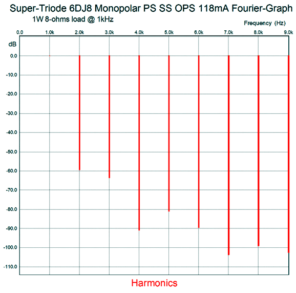
The input triode's current conduction need only vary a miniscule amount to cause the solid-state portion to fire up in response, swinging huge amounts of current as a result. The solid-state half of the amplifier inverts the input signal at its output, which is then returned to the triode's plate via the 10µF capacitor. If the output signal differs from the triode's amplification factor, the triode's current conduction will stray from its constant-current-source dictated idle current, which will prompt the solid-state output stage to fall in line. A monopolar power supply was used purposely, as the input triode's cathode connects directly the solid-state half of the amplifier. This eliminates the hornet's nest of problems, such as the power-supply noise on a negative power-supply rail and allows DC coupling at the input. Furthermore, the coupling capacitor at the output saves the speakers from DC offsets and thumping bumps at startup. How well did it perform in SPICE simulations? Not bad, as the follow Fourier graph shows.
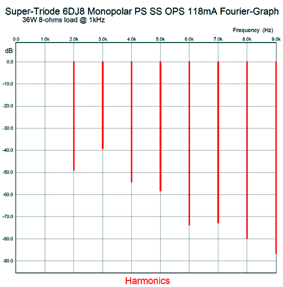
Almost single-ended in appearance, the THD distortion at 1W of output was about 0.1%. At full output, 36W, the harmonics shift upwards.
The distortion has climbed to a tad over 1%. What I didn't like was the high amount of 3rd harmonic, so I set about trying to eliminate it. Here was my solution: after burners transistors.
The added transistors are turned off at idle and only turn on when the output current against the 0.43-ohm collector resistors exceeds their threshold on voltage, about 0.6V. They cannot conduct wildly, as they are controlled by the primary output transistors, as these transistors monitor their current flow through their 0.22-ohm emitter resistors; in other words, a compound output stage is created. Well, did they do the trick? Yes, as the following graph shows.
The 2nd harmonic went up and the 3rd came down. This got me thinking about making the output stage a constant-gm design.
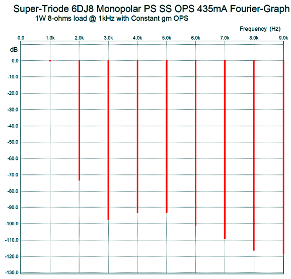
The added transistors are no longer in a compound configuration, but they are still turned off at idle. They turn on once the amplifier leaves its window of class-A operation, thereby doubling the gm for the half that is conducting, making for a constant transconductance output stage. In other words, the gm is always doubled, much as it is in a class-A push-pull amplifier. The idle current for the primary output transistors is a hot 435mA, which makes for a much fatter class-A window of operation, which shows in the 1W output graph.
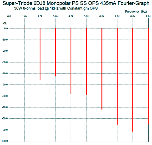
Note the reduced 3rd harmonic. At full output, the performance is not too different from the previous versions, as shown below.
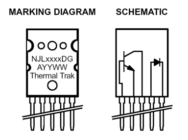
Although the higher harmonics are further reduced, it is not as single-ended looking as I would like. But the goal here was to get the first watt right, even if it came at the expense of the last watt. The primary output transistors are special. They are ON Semiconductor’s interesting new output transistors, the NJL3281D and NJL1302D, which hold their own biasing diode.
From the ON Semiconductor PDF. Basically, they are the old MJL3281A and MJL1302A transistors with an added rectifier. By using the two internal rectifiers to help set the bias voltage, the problem of thermal lag is lessoned. In SPICE simulations, this setup tracked fairly well.
Digital Electrostatic Loudspeaker Update
The next item I failed to mention was how we would electrically access each electrostatic ring. The answer is that if double-sided PCB material were used to make the stators, then we could easily use vias to bring the bottom side's rings to the top side, where thin traces would lead down to the bottom edge. If single-sided PCB material were used to make the stators, however, then we could use a pattern like the following.
(Imagine a few thousand small holes perforated in the PCB.) The actual traces would be much thinner in reality.
//JRB
User Guides for GlassWare Software
For those of you who still have old computers running Windows XP (32-bit) or any other Windows 32-bit OS, I have setup the download availability of my old old standards: Tube CAD, SE Amp CAD, and Audio Gadgets. The downloads are at the GlassWare-Yahoo store and the price is only $9.95 for each program. http://glass-ware.stores.yahoo.net/adsoffromgla.html So many have asked that I had to do it. WARNING: THESE THREE PROGRAMS WILL NOT RUN UNDER VISTA 64-Bit or WINDOWS 7 & 8 or any other 64-bit OS. I do plan on remaking all of these programs into 64-bit versions, but it will be a huge ordeal, as programming requires vast chunks of noise-free time, something very rare with children running about. Ideally, I would love to come out with versions that run on iPads and Android-OS tablets.
//JRB
|
|
Kit User Guide PDFs
Only $12.95 TCJ My-Stock DB
Version 2 Improvements *User definable Download for www.glass-ware.com |
||


.jpg)


| www.tubecad.com Copyright © 1999-2018 GlassWare All Rights Reserved |