| John Broskie's Guide to Tube Circuit Analysis & Design |
11 May 2014 Happy Mother's Day. I hope your mother appreciated the flowers and the matched quartet of output tubes you gave her.
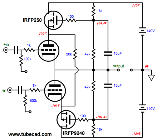
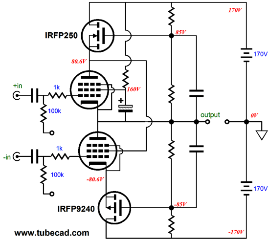
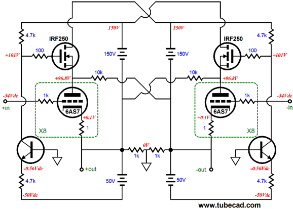
More OTL Design The main advantage to having the power-supply rail voltages climb and fall exactly (100%) with the output voltage swing is that it is the easiest arrangement to implement, requiring only a few extra resistors and capacitors, along with the two high-voltage, power MOSFETs, an N- and P-channel device, as the following schematic shows.
The pair of two-resistor voltage dividers (47k & 16k resistors) divide the power-supply rail voltages in terms of DC voltages by roughly 75%; in terms of AC output voltage swings, however, the shunting 10µF capacitors present 100% of the OTL's output voltage swing to the MOSFET gates. The result is that the output triodes work under a constant cathode-to-plate voltage. For example, if the OTL’s output voltage swings to +10Vpk, the positive power-supply rail voltage, the voltage at the N-channel MOSFET’s source, increases by 10V, while the negative power-supply rail voltage, the voltage at the P-channel MOSFET’s source, decreases by 10V. Thus, each output triode sees a fixed cathode-to-plate voltage, So, here is the interesting question: What is does the load-line look like in this setup, wherein the output tubes see a fixed cathode-to-plate voltage? Not really sure how a load-line works? Plotted against current and voltage, load-lines reveal the IV (current-voltage) dynamics of an output tube in use. Knowing how to create and read a load-line graph is one of the essential tasks of tube-amplifier design. Sad to say, but many tube-loving solder-slingers are baffled by graphs in general and load-line graphs in particular. Sad to say, but many tube-loving solder-slingers are baffled by graphs in general and load-line graphs in particular. Sad to say, but many tube-loving solder-slingers are baffled by graphs in general and load-line graphs in particular. Sad to say, but many tube-loving solder-slingers are baffled by graphs in general and load-line graphs in particular.
Undeniably, for many, far too many, a tube’s plate curves mystify and befuddle. Yet, load-line graphs are amazingly simple. Let’s start with the plot created by a single resistor. Can a single resistor be plotted? Oh yes indeed.
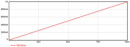
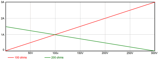
The Y-axis begins at 0A and ends at 1A, while the X-axis starts at 0V and ends 100V. The 100-ohm resistor’s plot begins at 0A and 0V and ends at 1A and 100V. This is the resistor’s load-line. We found the starting point at 0V & 0A by realizes that that with no voltage across the resistor, no current could flow. We selected the ending point by dividing the graph's end voltage (100V) by the resistor's resistance (100 ohms). What if the resistor had been a 50-ohm type and 100V divided by 50 ohms equals 2A, which is off the chart's Y-axis? We would place the end point at where ever the plot line intercepted the 1A line. In this example, we would multiply 50 ohms by 1A, as V = IR, which would place the end point at 50V. By inspecting the resistor’s plot-line, we see that at 50V, the current flow into the resistor equals 500mA; at 75V, 750mA. We also see that if we wish to produce 1A of current flow through the resistor, the voltage drop across the resistor must equal 100V. This is so simple it hurts—I know. But it could have been more interesting. For example, we assume that a 100-ohm resistor always equals 100-ohms, which is a fairly good assumption to make, as the resistor’s maker went to great trouble to ensure that for the most part it does equal 100-ohms. But is it resistance still 100-ohms at -200 degrees or at +200 degrees? Is it still 100-ohms with 1kV of voltage dropped across it? Reflect on what a miracle a typical, off-the-shelf, linear resistor is. A length of copper wire presents some resistance. How much? It depends on the temperature of the wire, which will vary with the current flow through the wire and the ambient temperature In other words, this piece of wire is less linear than the common resistor. If you ask the resistor maker, they will show you the resistor’s load-line plotted against current and voltage. It will not be a perfectly straight line. As the voltage increases, the resistance will either increase or decrease. This is phenomena called a “voltage-induced distortion,” or just “voltage distortion.” Of course, we usually first run into a resistor’s power limit before too much voltage is encountered, but not always. For example, a 1W 10Meg resistor has a theoretical voltage limit of 3,162V, as Vmax = Sqrt(WR), where W = power and R = resistance. But if you read the resistor’s data sheet, it probably states that the voltage limit is only 350V, as any greater voltage will simply arc across the resistor leads; and if you got to see the resistor’s actual load-line graph, it might show that the 10Meg resistance began to droop above 250V. The workaround in truly high-voltage circuits is to place ten 1W, 1Meg resistors in series, rather than use the single 10Meg resistor, as the voltage distortion will be much lower. Okay, now let’s make the load-line graph a bit more interesting by adding an extra resistor; say, a 200-ohm resistor.
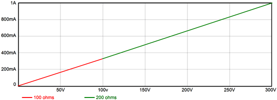
The two resistors are in series, with the 100-ohm resistor attaching to grounded and the 200-ohm resistor terminating at the B+ voltage. The graph’s X-axis has been increased up to 300V. Admittedly, this graph doesn't look any more interesting than the previous one. This is the result of the single plot line of the combined resistance of the two resistors. But if we make two plot lines, one for each resistor, things get more interesting.
Here, we see that if the resistors are hooked up across a 300V power supply, the 100-ohm resistor will see a 100V voltage differential; the 200-ohm resistor, a 200V differential. In addition, see at the two resistors intersection that the current flow into the resistor will equal 1A. If both resistors had equaled 150 ohms, then the same current would flow, but each resistor would see a 150V voltage drop. If we flip the resistors, so the 100-ohm resistor terminates into the B+ voltage and the 200-ohm resistor is grounded, then the same amount of current flows and the same voltage division obtains, although the plot lines are flipped. Adding a third resistor is easy enough; this time, a 300-ohm resistor.
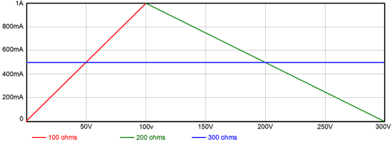
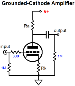
All three resistors are in series, with the 100-ohm resistor grounded and the 300-ohm resistor in the middle and the 200-ohm resistor terminating into the B+ voltage. We see that the current flow through all three resistors equals 500mA and that the 100-ohm resistor sees a 50V voltage drop; the 300-ohm resistor, 150V; and the 200-ohm resistor, 100V. Sure we could have done all of this in our heads, but what if the resistors had been non-linear? In that case, no one could do it in his head. (By the way, I just wrote “his” and not “hers” or “their.” Why? Because—quite simply—I am a he; if I had been a she, then I would have written “she.” No, it’s not a perfect scheme, but it is the one I like best, as I find the alternative "she-he-it" both clumsy and embarrassing. Of course, if the subject is a mother, I will use "she;" just as I would use "he," if the subject were a father. Where this system seems clumsy is when I use he as the pronoun for a nurse or flight attendant. Yes, I know that most nurses and flight attendants are female—but as long as there is at least one male nurse or flight attendant, I'll stick to this approach.) How did we know where to place the 300-ohm load-line? We add all three resistances together and divide 300V by it, which gives us the current flow through all three resistors. (For more on the topic of load lines and triodes, see my The Grounded-Cathode Amplifier PDF. By the way, a large percentage of the e-mail I receive could be eliminated, if the writer had read this article, as it answers so many of the questions that I am always asked, such as: How do I select the right cathode-resistor value?) A triode’s plate curve graph is a set of several resistance plots. Each plot line represents the effective resistance the triode presents from its cathode to its plate—at a specific fixed grid voltage. If we solder the grid to the cathode within the triode’s envelope, we would only get the 0V grid plot line and the triode would just be a non-linear power resistor—with the added oddity that it, unlike a typical resistor, could only conduct current in one direction. If, within the tube envelope, we had soldered in place a battery between the cathode and the grid, say a 3V battery, we would get a single plot line, the one that the -3V grid line traces; and once again, the triode would just be another non-linear power resistor, but with an odd difference. This power resistor would not conduct any current until a certain cathode-to-plate voltage had been reached. Thus, we see that the triode is actually a variable resistance, whose “turn-on” voltage and resistance is based upon its cathode-to-grid voltage.
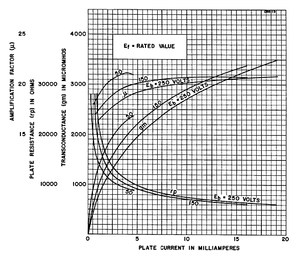
Because a triode is not linear resistor—normal resistors do not exhibit a “turn-on” voltage or curvature—we are faced with some difficulties. For example, if the 0V-grid line intersects the 100V cathode-to-plate voltage at 100mA, we might falsely assume that the plate resistance equals 100V/100mA or 1kohms. But a triode’s plate resistance (rp) is not a fixed, constant value, but a dynamically changing one, which depends on the triode’s grid voltage and cathode-to-plate voltage. To find the triode’s plate resistance at 100V with a grid voltage of 0V, we would measure the current flow at 90V and at 110V and then take the average and divide 100V by it. The result is likely to be lower than 1kohm. In other words, a triode’s plate resistance represents the slope of the resistance plot at a certain point of the triode’s operation. It is resistance is higher at low currents and lower at high currents. The steeper the line, the lower the resistance. Much as a triode’s plate resistance varies, so, too, does its transconductance (gm). Wait a minute, aren't these tube constants? No. They are more like your weight and height, which vary as you age. Obviously, your weight over time plot can resemble a roller coaster layout. And even your height does not define a straight line against age, as there are growth spurts and the decline in stature that comes with old age. Below, we see the gm, rp, and mu plots for a 6SN7, which is a very linear triode, yet there are no straight lines.
A triode’s amplification factor (mu) is a derived variable that results from multiplying its gm against its rp. It is useful, and much closer to being a constant than the triode’s gm and rp, but it is also less real than the other two attributes. For example, we can create a derived attribute, HW, which would equal your height divided by your waist measurement. This ratio may somewhat hold throughout your life, from birth to death, excepting when being pregnant and the college-freshman weight gain. Modeling agencies have many “ideal” ratios to which an aspiring model must conform. But their ratios, like HW, are all derived from more “real” attributes, such as her height, waist, bust, hip... measurements. (There are plenty more measurements, but this is a family-friendly blog.) On the other hand, for those at the modeling agency, their all-important ratios are effectively more real, more important that the base attributes from which they are derived.
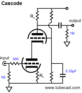
Tube-fanciers use mu all the time and believe in it wholeheartedly. But if the predominate tube circuit had been the cascode, not the grounded-cathode amplifier, then few would even know what a triode’s mu was, as the triode’s gm would be the triode’s key attribute.
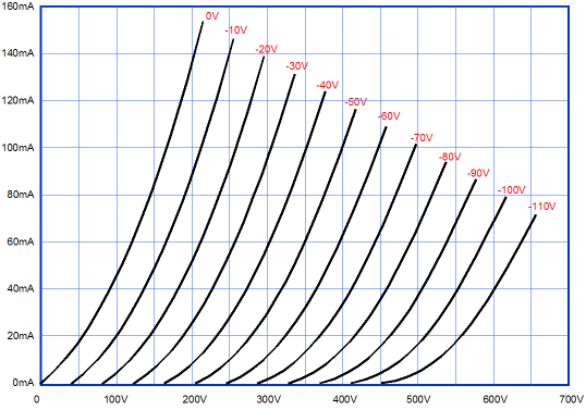
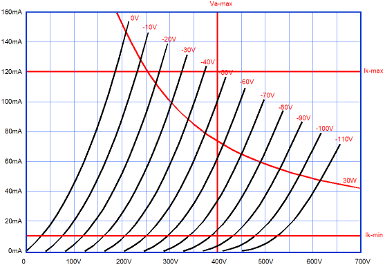
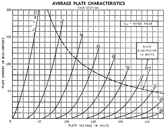
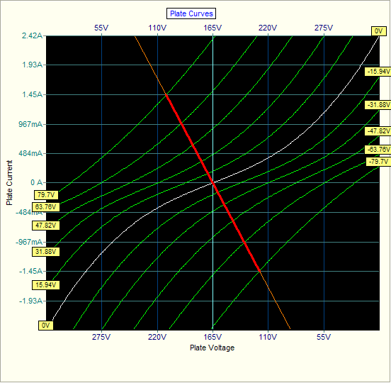
Indeed, a new "mu" might have been put in place, which was the result of multiplying the triode's gm against a 10k plate resistor. With this alternate "mu," a 12AX7's mu would only be 16; and a 6AS7, 70! Speaking of the 6AS7, below we see the plate curves for a 6AS7 triode, which is not a very linear triode, but it can deliver a lot of current with little cathode-to-plate voltage, which explains its use in OTL power amplifiers. If we use this triode in a constant-cathode-to-plate voltage topology, with a constant 100V cathode-to-plate voltage, what does an 8-ohm load-line look like? What does an 800-ohm load-line look like?
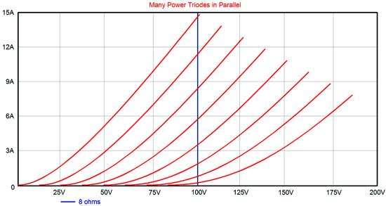
Okay, those were trick questions, as both load lines would look the same: a straight vertical line at 100V. But first, let's look at a conventional OTL load-line, whose power-supply rail voltages are fixed.
The load ia 8 ohms and the power-supply rail voltages are+/-100V, so we draw a line that starts at 100V and 0A, then we divide 100V by 8 ohms to get the Y-axis intersection (12.5A). The 0V grid line, the leftmost one, intersects the load-line at 6A, which implies a peak output wattage of 6A² x 8-ohms/2 or 144W. (Mind you, if we drive the grid positively, we can get much more watts.) Now, lets plot the load-line with a modified OTL that uses a constant cathode-to-plate voltage.
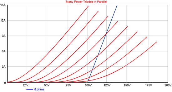
Effectively, the load resistance equals 0-ohms; and we notice is that peak output current has gone from 6A to close to 15A, which would equal 900W! Reality is bound to disappoint, as 15A against 8 ohms means 120Vpk of voltage swing, which OTL's power supply is not likely to supply; and even if it could, at that current draw, it would soon collapse, unless the power transformer weighed a few hundred pounds. Note that with an effective load of zero ohms, the triode does not benefit from any degenerative feedback from load. In other words, although more current will be forthcoming, the distortion will be higher. No free lunches ever. Now, what does the load-line look like when the OTL's power-supply rail voltages increase beyond unity and grow larger than the output swing? Effectively, the load resistance goes negative.
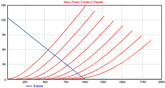
The peak output current is off the charts (well, at least this chart). Needless to say, we can expect even more output wattage than the OTL that uses a constant cathode-to-plate voltage can put out and far more than a conventional OTL can put out with is fixed power-supply rail voltages. Impressive, no? Okay, before anyone gets the urge to complain that the plate curve for a single triode are not enough, as what we really need is the combined plate curve for two triode in push-pull opposition, which will be both more linear and exhibit a higher transconductance. True, all very true. But as most OTL amplifiers use relatively light idle currents, the conduction overlap is usually small and our concern is the power limit, where one output tube would be completely shut off.
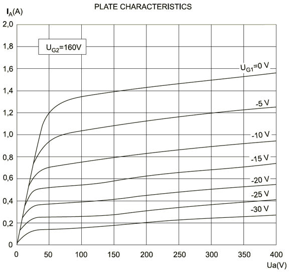
So far, we have looked at power triodes, such as the 6AS7 and 6C33 and 12B4, but what about power pentodes, such as the EL509? Triodes are different. They differ radically from pentodes, MOSFETs, transistors, and FETs. How so? Triodes embody a relatively low plate resistance; the other devices do not. Below is the set of plate curves for the JJ EL509.
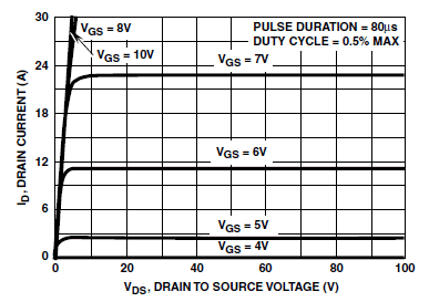
Truly an impressive amount of current flow from a single tube. So, it is no wonder that it is often used in OTL amplifier. Note how it can deliver well over 1A with a cathode-to-plate voltage of just 50V. Also note how that going from 100V to 150V to 200V does not make much of a difference in current flow. Going from 100V to 200V only resulted in a an increase of only 80mA or so—at the cost of twice the dissipation. MOSFETs are even worse in this regard. Below is the current-voltage graph for the N-channel IRFP240.
Note how going from a source-to-drain voltage of 20V to 40V to 80V made zero difference in current flow. Now wonder that MOSFETs make such good constant-current sources. In other words, if our goal is increased power from an OTL amplifier, my variations on the theme of expanding-contracting power-supply rail voltages only works—as a means of extracting more current from the output tubes—with triodes. Of course, a pentode-based OTL design, such as the one shown below could benefit from reduced dissipation at idle and from an improved PSRR. In addition, such a design may effectively wring much more output from the pentode output tubes, as its reduced dissipation at idle and its fleeting rail voltage expansions may work to keep the tube safe, so more power could safely be squeezed from them. In other words, this doesn't mean that an OTL based on EL509 output tubes cannot beat one based on 6AS7 tubes, in terms of peak power output; it just means that the pentodes high plate resistance precludes the extraction of gobs of extra cathode current as it did with power triodes.
Note how the pentodes, JJ EL509 types for example, see a constant cathode-to-plate voltage. Also note how the raw power-supply rail voltages are halved by the pair of two-resistor voltage dividers. With the voltages shown in the schematic, we can attach the bottom pentode's G2 (grid-2 or screen) to the top pentode's plate, saving the need for a power resistor and capacitor.
Supercharged Circlotrons
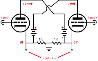
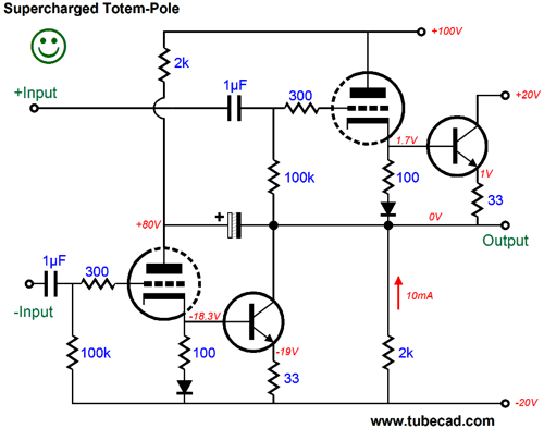
An imagined advantage is the strange belief that this topology, much like the single-ended amplifier, can only be run in class-A. Nonsense, pure nonsense. The Circlotron is push-pull topology, not a single-ended one. As one tube conducts more, the other conducts less. Indeed, either tube can be and will be completely cutoff at full power output, as no common power triode, such as the 6AS7 or 6C33, can withstand the high idle current flow, half of the peak current output, or the dissipation that such a high idle current against the high cathode-to-plate voltage. If a true class-A, 64W Circlotron power amplifier were to be built, it would require a power supply the size of a large microwave oven or small refrigerator and 30 6AS7 output tubes per channel, whose heater current draw alone would be 75A. Yes, 75 amperes. Configuring a Circlotron so that it runs its output tubes under a constant cathode-to-plate voltage is amazingly simple, as the following schematic shows.
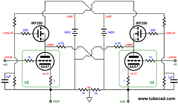
As the left triode swings positively, so does its plate voltage; conversely, at the same time, the right triode swings negatively, as does its plate voltage. The much harder problem is getting more than unity increases and decreases in the triode's rail voltage—applying voltage gain to the rail voltages, in other words. After some head scratching, I came up with the following design.
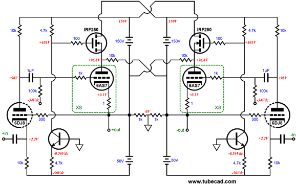
The two high-voltage NPN transistors have their based grounded and are configured as common-base amplifiers. As the two floating 50V power-supply rails swing up and down with the output voltage swings into the speaker, the two 4.7k emitter resistors see a varying current flow, which the two 4.7k collector resistors reflect. In addition, the two floating 50V power-supply rails also swing up and down with the output voltage swings. The result is a voltage gain of two. In other words, for every volt of swing at the output triode's cathode, its plate sees twice that swing. Supercharging, in a nutshell. Moving one step back from the naked supercharged Circlotron output stage, we see a simple driver stage added.
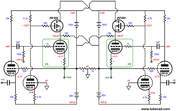
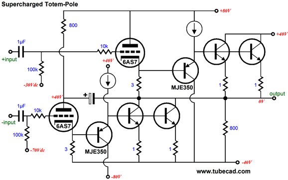
The two 6DJ8 triodes are configured as grounded-cathode amplifiers (the real ones, not the misnomer cathode-coupled amplifier). But rather than actually ground the grids, they are attached to the outputs. A short, fast negative-feedback loop, in other words. If the grid signal fails to match the input signal at the cathodes, the triode reacts in a countervailing fashion, which brings the 6AS7 output tube in line. Although it looks like the 6DJ8 cathodes will present a very low input impedance, they don't. As the 10k cathode resistors move in sync with the output swings, and as cathodes follow the output swings, the actual input impedance is much higher than you would assume. Gee, John, this is sure a nice circuit, but to be honest all those solid-state devices creeps me out. Understood. I feel your apprehension. We cannot lose the power MOSFETs, but we can lose the two transistors, as an NPN transistor can be replaced by a triode.
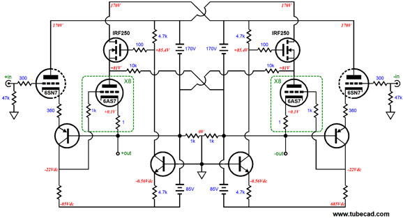
All the 6DJ8 triodes are now configured as grounded-grid amplifiers, which are analogous to the transistor common-base amplifier. Now to end this topic with the schematic from the end of the last post, the Bastode driver stage.
The 6SN7 triodes and the PNP transistors define Bastode differential amplifiers. We still get a negative-feedback loop to control the output tube behavior and an even higher input impedance. In addition, we get DC coupling to the output tube grids.
Other OTL Supercharging Possibilities
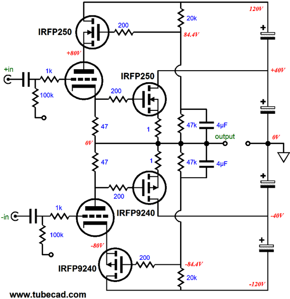
Here is another example from that post. In these two examples, power transistors were used, but with a few adjustments power MOSFETs could be used instead. In fact, we could meld both the constant-cathode-to-plate voltage concept with power solid-state devices in parallel with the power triodes, as shown below.
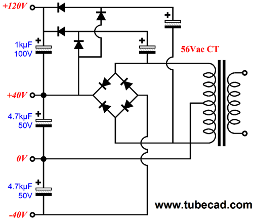
The two triodes drive both the speaker and the two output MOSFETs. If carefully set up, the tube may never cutoff, running class-A throughout the output waveform. The MOSFETs, on the other hand, would run in class-AB. (Of course, if you have the budget and the heatsink and power transformer for it, the MOSFETs could be run in class-A.) Such a hybrid power amplifier would not require a bank of many output tubes, as one 6AS7, a dual triode, per channel would suffice. (Or, we could use two 300B output tubes, which much higher rail voltages, say +/-150Vdc.) The power supply for the above circuit can be made from a 56Vac CT power transformer, with the rectifier topology shown below.
Next Time
Since I am still getting e-mail asking how to buy these GlassWare software programs:
For those of you who still have old computers running Windows XP (32-bit) or any other Windows 32-bit OS, I have setup the download availability of my old old standards: Tube CAD, SE Amp CAD, and Audio Gadgets. The downloads are at the GlassWare-Yahoo store and the price is only $9.95 for each program. http://glass-ware.stores.yahoo.net/adsoffromgla.html So many have asked that I had to do it. WARNING: THESE THREE PROGRAMS WILL NOT RUN UNDER VISTA 64-Bit or WINDOWS 7 & 8 or any other 64-bit OS. One day, I do plan on remaking all of these programs into 64-bit versions, but it will be a huge ordeal, as programming requires vast chunks of noise-free time, something very rare with children running about. Ideally, I would love to come out with versions that run on iPads and Android-OS tablets.
//JRB |
I know that some readers wish to avoid Patreon, so here is a PayPal button instead. Thanks. John Broskie
Kit User Guide PDFs
And
High-quality, double-sided, extra thick, 2-oz traces, plated-through holes, dual sets of resistor pads and pads for two coupling capacitors. Stereo and mono, octal and 9-pin printed circuit boards available.
Designed by John Broskie & Made in USA Aikido PCBs for as little as $24 http://glass-ware.stores.yahoo.net/
The Tube CAD Journal's first companion program, TCJ Filter Design lets you design a filter or crossover (passive, OpAmp or tube) without having to check out thick textbooks from the library and without having to breakout the scientific calculator. This program's goal is to provide a quick and easy display not only of the frequency response, but also of the resistor and capacitor values for a passive and active filters and crossovers. TCJ Filter Design is easy to use, but not lightweight, holding over 60 different filter topologies and up to four filter alignments: While the program's main concern is active filters, solid-state and tube, it also does passive filters. In fact, it can be used to calculate passive crossovers for use with speakers by entering 8 ohms as the terminating resistance. Click on the image below to see the full screen capture.
Tube crossovers are a major part of this program; both buffered and un-buffered tube based filters along with mono-polar and bipolar power supply topologies are covered. Available on a CD-ROM and a downloadable version (4 Megabytes). |
||


| www.tubecad.com Copyright © 1999-2014 GlassWare All Rights Reserved |