| John Broskie's Guide to Tube Circuit Analysis & Design |
| 31 August 2013 New Octal Aikido
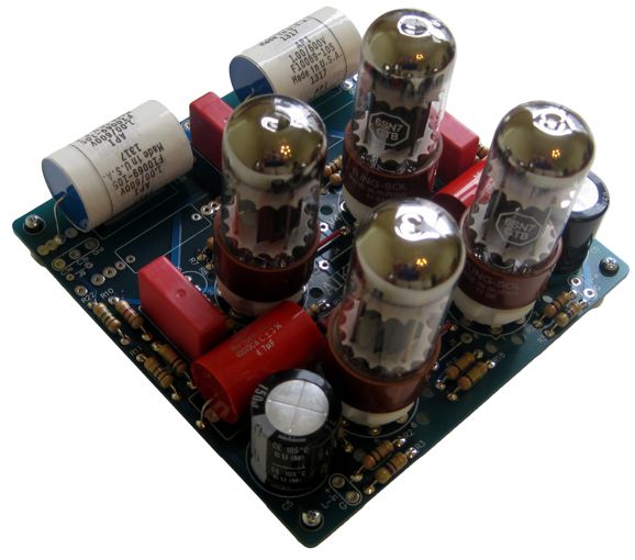
New GlassWare Octal Aikido PCB & Kit
In addition, the PCB can hold two sets of output capacitors and and can be configured as an Aikido Push-Pull circuit, for driving low-impedance loads, such as 300-ohm headphones.
I have been listening to noval tube circuits exclusively for the last few months (with the exception of my octal headphone amplifier). As the first played the first notes of one of my favorite blues albums passed through the Octal Aikido shown above, I heard that wonderfully distinctive octal sound, a full, solid sound that demands my attention. I like it. And I wasn't aware of how much I had missed it, until I heard it resound again.
By the way, the tubes shown above are the new Russian 6SN7 Tungsol reissues, which sound quite good.
All things considered, which they never are (how could they be?), the new Octal Aikido PCB with the Tungsol 6SN7 tubes and the API/RTI coupling capacitors makes a wonderful foundation for a truly giant-killing line stage. Of course, much more is needed, such as a power supply and selector switch and volume control and box. Nonetheless, I cannot see any cheaper way to ascend to sonic glory. The Aikido Octal stereo PCBs and kits are available now at the GlassWare/yahoo store.
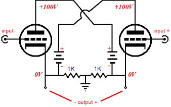
Push-Pull Tube Operation If a balanced input signal is available, two output tubes and not much more—an output transformer and a few resistors—is needed to build a push-pull output stage.
Or, if two floating power supplies are used per channel, we can forgo the output transformer and build a circlotron circuit.
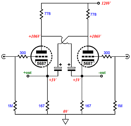
On the other hand, we could replace the floating power supplies with large-valued capacitors and a single grounded power supply, as the following circlotron circuit does.
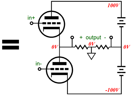
Unlike the the circlotron circuit shown before it, this version must be run in strict class-A, as prolonged class-B operation will discharge the two large capacitors. We can even turn the horizontal circlotron into a vertical circlotron circuit by rearranging the six components; thereby creating a functionally equivalent circuit, with the same gain and output impedance. And like its horizontal brother, this version can be run in class-AB or class-B.
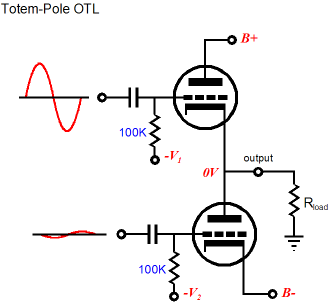
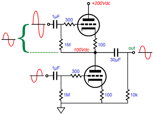
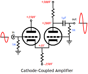
Yes, it does look similar to a typical totem-pole OTL output stage, but is is quite different because of where the "ground" falls and the bipolar power supply floats, rather than being "grounded." In addition, the above circuit must see a balanced input signal with equal amplitude in both phases, whereas the OTL output stage below must see dissimilar amplitudes in the two phases, with the top triode seeing a much larger input signal, as the top triode's cathode follows its grid, while the bottom triode's cathode is "grounded." (It is grounded in AC terms, although the cathode terminates into the B- Rail.)
Only when the load impedance is zero do both top and bottom triodes would see identical signal amplitudes, but in opposite phase. As the load increases in resistance, the top triode must see a larger input signal than the bottom triode. If the load approaches infinity, then the top triode must see the biggest difference in signal amplitude. If compare the cathode-to-grid signals, we would see that both top and bottom tubes see the same signal amplitude; but relative to ground, they do not.
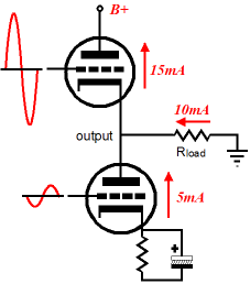
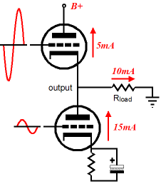
The following schematics show how push-pull operation works. The external load sees the difference, the delta, in conduction between the top and bottom triodes. In this example, with an idle current of 10mA, we see 15mA - 5mA, which results in +10mA flowing through the load resistance. Then, with the phase reversed, we see 5mA - 15mA, which results in -10mA flowing through the load resistance. With one triode completely cut off (zero current conduction) and the other triode conducting at twice the idle amount, the load sees 20mA of current flow, as 0mA - 20mA equal -20mA. If we choose to go beyond the limits set by class-A, then the engaged triode can draw 30mA, 40mA, or more of current, which the load would entirely see, as the other triode is completely cutoff as if it were not there, so the only path the current can take is from ground through the load and then through the triode to the B+ connection.
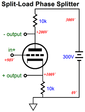
The problem is that once we leave the class-A-window of conduction, the output impedance doubles and the distortion rises; moreover, the power supply gets banged about much more, as the average and the maximum current draw are no longer identical. In other words, we must pay for the big increase in power output. But what if we do not have a balanced input signal available, how do we drive a push-pull circuit? The active solution is to convert the unbalanced input signal into a balanced signal, with an active phase splitter, such as the split-load phase splitter or a singal transformer with a center-tapped secondary.
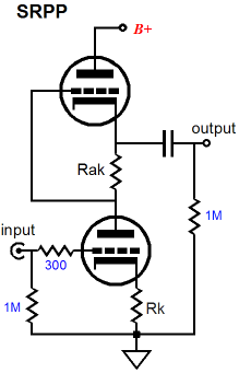
Phase-inverter-free solutions are more interesting, as the circuits must contain their own internal (and hidden) phase inverter. The most famous example might be the SRPP, which accepts an unbalanced input signal and delivers push-pull operation into an external load resistance. (The external load is an essential part of the circuit and its resistance must be factored in the SRPP's part values. In other words, the SRPP is load-resistance sensitive and must be optimized for a given external load resistance.)
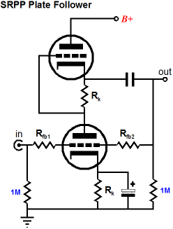
The SRPP delivers voltage gain and a rather high output impedance, which can be improved upon by adding a negative-feedback loop, at the cost of reduced gain.
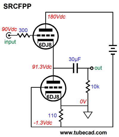
Working backwards and assuming that Rfb1 and Rfb2 are equal in value, if a positive voltage pulse is applied to the output, say a 1.5V battery being momentarily attached to the output and ground, the bottom triode will see half of the positive pulse voltage at its grid, which will prompt the triode to conduct more current, pulling the output down. At the same time, the top triode will see a larger voltage drop across its cathode resistor and its cathode voltage move up with the pulse, which will force a decrease in its conduction, reducing its ability to pull up. The net result is that both triodes aggressively buck the imposed pulse at the output, thereby reducing the output impedance. An interesting twist is the circuit that I call the SRCFPP, the Series-Reflexive Cathode Follower Push Pull circuit. Here no voltage gain obtains, as the input triode function as a cathode follower. Be sure to note where the ground falls in this circuit: right at the bottom triode's cathode. But as the power supply is not "grounded," the 110 cathode resistor still functions as a cathode resistor; it also functions as a current sense resistor, which will develop an Inverted AC input signal for the bottom triode.
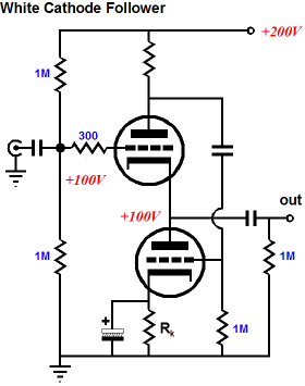
The key feature about the SRCFPP circuit is that it requires one floating power supply (the battery in the schematic) per channel, no shared power supply. A circuit of DC current flow is created through the two triodes and the 110-ohm sense resistor and the floating power supply. This circle of DC current flow does not include the external load, as the coupling capacitor blocks the external load from experiencing the flow. With an AC input signal, however, the external load resistance becomes a critical part of the circuit, as it will receive the difference, the delta, in current conduction between the top and bottom triode. Why should the these t6wo triodes ever differ in conduction? The answer is that as the output signal current flows through the external load and through the 110-ohm cathode resistor, an inverting input signal is created for the bottom triode. For example, as the top triode conducts more, the bottom triode conducts less, as its grid-to-cathode voltage becomes ever more negative; as the top triode conducts less, the bottom triode conducts more, as its grid-to-cathode voltage becomes ever more positive. In a way, the SRCFPP circuit is the White cathode follower circuit stood on its head. Speaking of the White cathode follower, it, too, is a push-pull circuit that creates its own inverting signal, in spite of an unbalanced input signal.
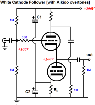
Just like the SRPP and SRCFPP, the White cathode follower is load sensitive and must be optimized for a specific load impedance, as the external load becomes an essential part of the circuit. One problem with the White cathode follower circuit is that requires a very clean power supply connection, as the B+ ripple becomes an input signal to the bottom triode at its grid. As I have shown before, there is an Aikido-esque workaround.
The cathode resistor gets two bypass capacitors. The top bypass capacitor, C1, injects a countervailing amount of power-supply ripple to the cathode, so the ripple on the grid is countered, as it meets an equal amount of ripple on the cathode, so the delta is zero. The big problem with this fix is that electrolytic capacitors seldom match their value; and, unfortunately, electrolytic capacitors will be needed, as only they offer sufficient capacitance. Many electrolytic capacitors manufacturers, however, work on the premise that the marked value is only a bottommost guarantee, so a 1kµF must hold at least 1kµF of capacitance, so 1.3kµF is fine, as the customer was not cheated of his promised capacitance. If you are building a power supply, this is good news, but if you are building a speaker crossover or trying to null ripple, this over achievement is a pain. Well, our task would be easier, if we could rely on 1% resistors instead of sloppy electrolytic capacitors. This leads to my latest variation on the venerable White cathode follower.
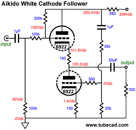
Aikido White Cathode Follower
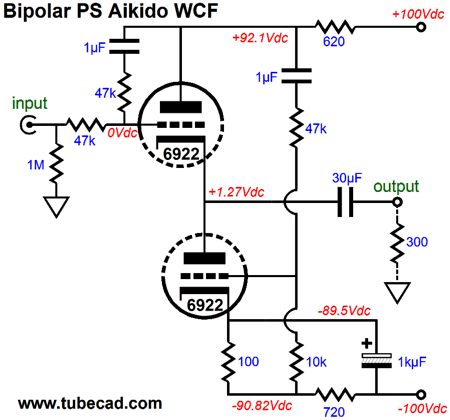
First of all, note how the 200k and two 100k resistors provide the 50% DC voltage division for the top triode's grid. Also note how these resistors throw away 33% of the AC input signal. In addition, they allow 33% of the ripple that appears the top triode's plate to be injected into its input signal. At the same time, the bottom triode sees a mix of the ripple and its needed inverted input signal at its grid. The result is push-pull operation and a power-supply noise null at the output, which entails a small insertion loss, sadly. Sadly because most DACs and CD players only put out about 1Vpk, which is not enough for most 300-ohm headphones. Using a bipolar power supply allows us to forgo the input coupling capacitor but slightly increases the insertion loss, as the two 47k resistors halve the input signal. The grid biasing of the bottom triode may seem a tad overly elaborate, but it does ensure that both triodes see the same cathode-to-plate voltage. The 47k and 10k voltage-divider string of resistors inject the required amount of power-supply noise to create a noise null at the output.
As I look at this schematic, I can see a new variation. Yes, indeed, there is no limit; each circuit can give rise to numerous variations, which in turn, give rise to numerous variations.
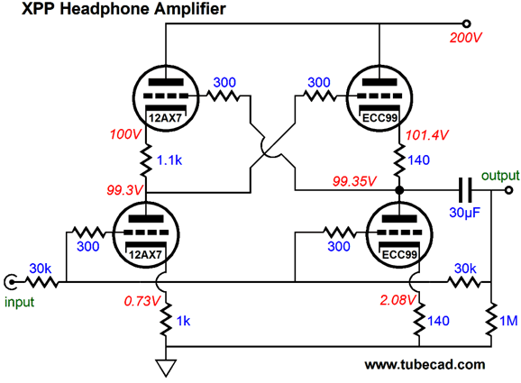
XPP Amplifier
(Several readers have written to me, detailing how how much they like this circuit, finding its sonic signature quite compelling, so do not make the mistake of dismissing it out of hand.) Adding a negative-feedback loop lowers the output impedance and the distortion.
The single coupling capacitor is a big feature. In addition, the unbypassed cathode resistors in the output stage increase the ECC99's linearity. All in all, it looks like a fun circuit to play with.
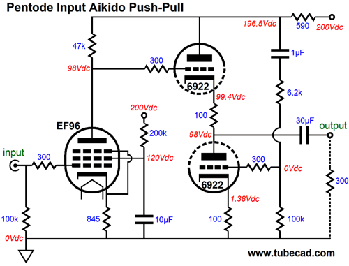
Pentode-Input Aikido Push-Pull
The EF96 is a fun pentode that was created for audio use. The 6922/6DJ8/E88CC is a readily available triode that offers a lot of transconductance; if greater power output is needed, the 5687 or ECC99 are good choices. Since almost all of the power-supply noise will appear at the pentode's plate, the two-resistor voltage divider must inject almost all of the power-supply noise into the bottom triode's grid to achieve a noise null at the output. At the same time the 590-ohm series resistor at the top will create the required inverted signal for the bottom triode. Once again, this circuit is load sensitive.
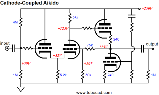
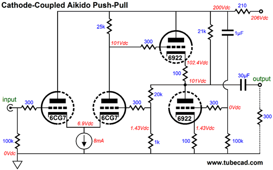
Cathode-Coupled Aikido Push-Pull
I have already created an Aikido version of the cathode-coupled amplifier.
The question is: Can this circuit be converted into one with a push-pull output stage? The answer: yes. In fact, it was much easier than I expected. The first step was to add a series resistor; in this example, 210 ohms. This resistor will create the needed inverted input signal for the bottom output triode. The second step is to realize that the cathode-coupled amplifier, with a constant-current source at the bridged cathodes, will offer a PSRR of nearly zero. In other words, all the power-supply noise at the top of the 25k plate resistor will appear at the bottom of the plate resistor. This means that we will not need a voltage-divider resistor string, as we must inject all of the power-supply noise into the bottom output triode's grid.
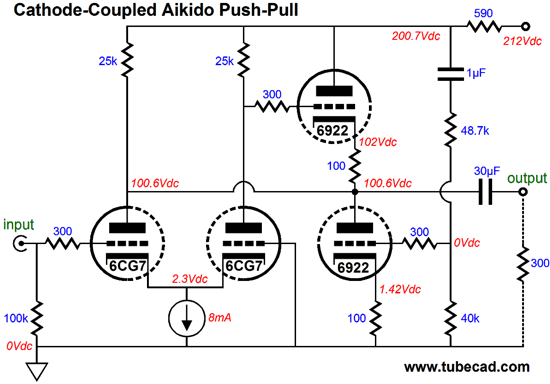
The third step is to establish the required grid-bias voltage for the cathode-coupled amplifier's right triode. This is critical, as this triode sees the same cathode voltage as the left triode (they do share a common cathode connection to the CCS after all), but only half of the plate voltage. The solution is to make a DC voltage divider based on the triode's mu (amplification factor), so that the right grid sees 1/mu amount of the right plate voltage. Since the 6CG7 has a mu of about 21 at this plate voltage and current draw, a 20k and 1k resistor were used. This resistor string will drag down the output stage a tad, so a compensating 21k resistor was added that pulls up as much as they pull down. The voltage divider will also introduce a wee amount of negative feedback, which can be eliminated by shunting the 1k resistor will a large capacitor, which will allow the DC sampling to to work, but not pass the AC signal. As I looked at the schematic, I wondered if I could free up the right grid in the input stage, so the input stage could accept a balanced input signal. This would only be possible if both plates saw the same cathode-to-plate voltage. After some fiddling, the following simple circuit was created.
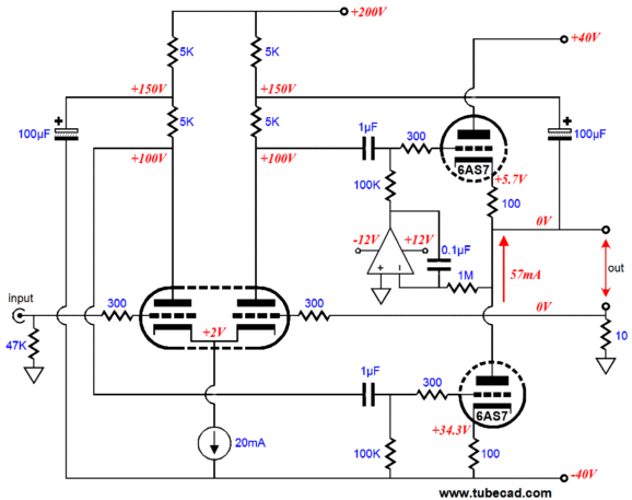
Only the input-stage's right triode really gets a plate resistor, as the left triode's plate terminates into the circuit's output and the extra 25k resistor's only job is to pull the output back into mid voltage. (This resistor could be replaced by a 4mA CCS.) (I know how solder slingers think, so I should have placed the 25k resistor to the right of the 6922, which would have not altered the circuit's functioning in the least, but would have made the resistor appear less like a plate resistor.) By the way, because we terminated the input-stage's left triode's plate into the circuit's output, we get an even lower input capacitance, when set up for unity-gain, as both the input cathode and plate will move in phase with the grid. Another by the way, the constant current source could be replaced by a large-valued cathode resistor that terminated into a negative power-supply rail. This would eliminate the need for a solid-state CCS and it would allow the circuit to breathe with the falling and rising wall-voltage shifts, assuming a non-regulated power supply were used. I would draw the schematic, but my fingers are getting tired. Instead, here is an old schematic that shows four triodes can be arranged into a push-pull amplifier that is load-independent.
This schematic assumes the use of the GlassWare PS-6, which establishes the +/-40V rails and a single +200V rail for the input stage from a single 56Vac CT secondary. This amplifier is not a voltage-output amplifier but a current-output amplifier. They are different. To convert it into a voltage-output amplifier requires attaching the load across ground and the output.
Next Time
//JRB |
I know that some readers wish to avoid Patreon, so here is a PayPal button instead. Thanks.
John Broskie
E-mail from GlassWare Customers
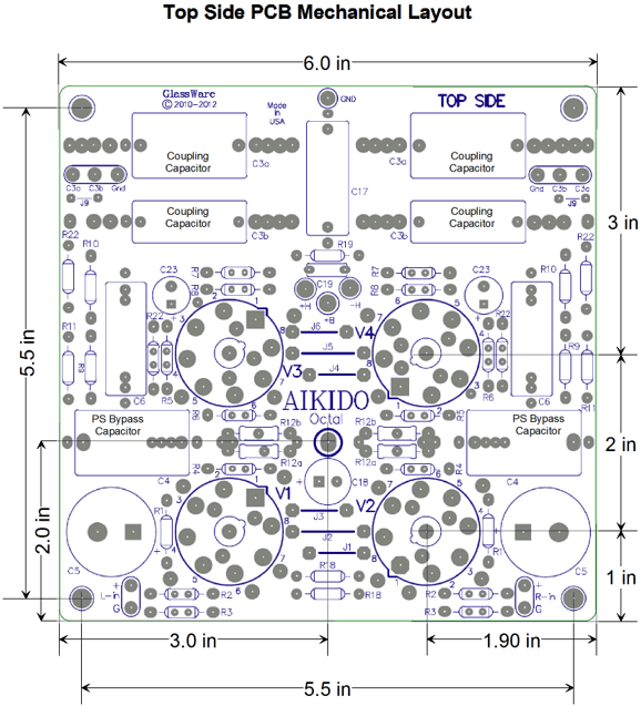
High-quality, double-sided, extra thick, 2-oz traces, plated-through holes, dual sets of resistor pads and pads for two coupling capacitors. Stereo and mono, octal and 9-pin printed circuit boards available.  Aikido PCBs for as little as $24 http://glass-ware.stores.yahoo.net/
Support the Tube CAD Journal & get an extremely powerful push-pull tube-amplifier simulator for TCJ Push-Pull Calculator
TCJ PPC Version 2 Improvements Rebuilt simulation engine *User definable
Download or CD ROM For more information, please visit our Web site : To purchase, please visit our Yahoo Store: |
|||


| www.tubecad.com Copyright © 1999-2013 GlassWare All Rights Reserved |