| John Broskie's Guide to Tube Circuit Analysis & Design |
|
Post 251 25 December 2012
Merry Christmas! I hope that you got all that you wished for and more. I have shoveled the snow and had my Christmas meal, which included much wine, so writing is easy. Speaking of writing, I had hoped that I might be finishing blog post number 300 by now, but alas no. Maybe next year. (If I broke up my many super long posts into two or three posts or even four posts, I would be closer to post number 1,000.)
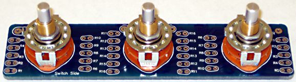
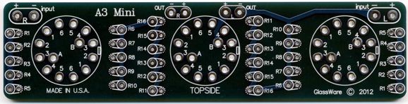
A3-Mini Stepped Attenuator
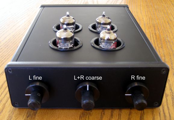
So, why did I make a mini version? Small enclosures require a smaller three-knobbed stepped attenuator. For example, the A3 Mini fits in the following Aikido line stage that I built using a Hammond extruded 6.5in wide enclosure, model 1455T2201BK. (This Aikido uses four JJ 6922 tubes and runs off a 12Vac wallwart. More details on this design will be forthcoming in a future blog post.) Note the positions of the left and right fine attenuators switches. much like a microscope, the fine attenuators are first placed at their mid-position, then the coarse control is adjusted to a suitable volume level, then the fine controls are used to set the balance or to make fine adjustments.
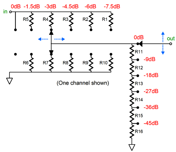
This cleverly designed stepped attenuator exploits both the series-attenuator and the ladder-attenuator stepped-attenuator configurations to yield the best compromise between flexibility, performance, and cost. The A3 Mini attenuator uses three rotary switches and 32 resistors to yield a total of 36 positions of attenuation in -1dB or 1.5dB or -2dB and -6dB or or -9dB or -12dB decrements. Had the attenuator been entirely of a series design, the attenuator would require 36-position rotary switch and 72 resistors; a purely ladder design, a two-deck, 2-pol, 66-position rotary switch and 140 resistors. In contrast, the A3 Mini attenuator, from 0 to the first 6 steps of attenuation, is solely a ladder attenuator, with no more than two resistors in the signal path; thereafter, the attenuator uses both a ladder and series configurations, with never more than 7 resistors in the signal path. The A3 Mini PCB and rotary switches and resistors are now available at the GlassWare Yahoo store. The options for the optional resistor packs are metal-film or carbon-film, -1dB/-6dB or -1.5dB/9dB or -2dB/-12dB increments. (The standard A3 attenuator can now also be bought with -1.5dB and -9dB steps with 20k input resistance.) I added the -1.5dB/-9dB option, as it is a good compromise between the other two; it is only available in 20k input resistance values.
Circlotron Redux
The request was the always the same: How could this topology be converted into a conventional Circlotron with no inductors? And are the PNP transistors absolutely necessary? Well, losing the inductors is easy.
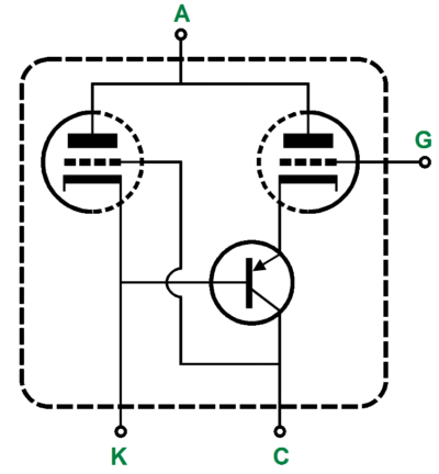
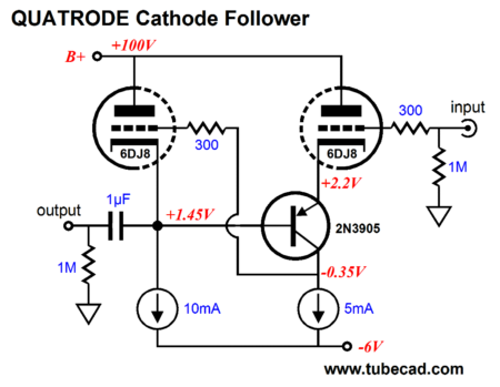
What is much more difficult is losing the PNP transistor, as their is no tube equivalent, alas. What is needed is a non-inverting amplifier that uses its inverting input to provide negative feedback, which this hybrid inverted cascode circuit does quite well. Note how PNP transistor's base attaches to the output, which allows the output signal to be presented to the driver tube's cathode, creating a negative feedback loop. This topology has appeared here before, labeled the quatrode. See Blog Number 199. This cluster, this scheme, this arrangement of two tubes and one transistor can be viewed as having only four elements—in spite of the nine actual device elements present—that then attach within other circuits, such as buffers and amplifiers.
This Circlotron variation used the quatrode in the cathode-follower configuration.
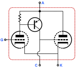
The quatrode comes in a second form, which moves the PNP transistor to top of the output tube' plate.
Once again, we have four elements, but the input triode, the one on the left, receives the negative feedback directly at its cathode. Blog Number 214 showed how this seconded version of the quatrode could be used to make a Circlotron output stage, as show below.
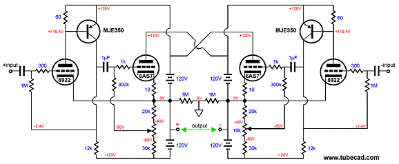
So, how do we retain functionality of the PNP transistor while removing it from the Circlotron output stage? Well, one aspect of the Circlotron that can come in handy is that it is a balanced design that presents a positive and negative output (and a ground midpoint). In other words, if we cross-couple the driver triodes, we can establish two negative feedback loops, one at the driver tubes' cathodes and at their plate resistors.
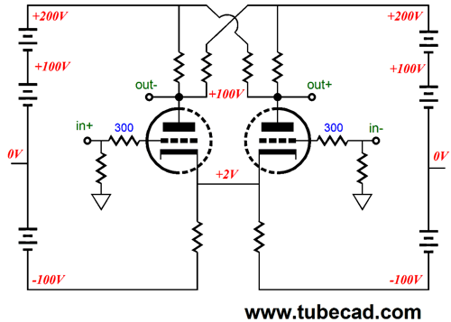
This schematic shows DC coupling only to make the circuit's functioning clearer, not because it is a good idea! If the ECC99 driver tube was missing from its socket, watch out, as the output tubes would see +100Vdc on their grids relative to their cathodes. Also note that the output is at +100Vdc. Ouch! of course, if the Circlotron were built within a speaker enclosure, where the user could not access the output terminals, the there would be no danger in letting the output sit at 100Vdc. Or, we could use an isolation transformer (or a very low-ratio output transformer) to make this Circlotron safer. (It is easy to make a great isolation transformer, as the parasitic capacitance aid its functioning, rather than hinder it, unlike what happens in a conventional step-down output transformer.) Another approach would be to use grounded-grid amplifiers in the driver stage.
The driver triodes are driven at their cathodes and they do not invert the phase at their plates, as a grounded-cathode amplifier would. The NFB is taken at the grid. Note how both the cathode and plate resistors are bootstrapped by their connection to the power supply, which is referenced to the positive and negative outputs. In other words, the 10k cathode and plate resistors are effectively much larger in value, which will greatly increase the driver stage's input impedance, which would otherwise prove a pain to drive and would require huge coupling-capacitor values. No doubt, many readers are overly concerned about the six battery symbols used in the above schematic. Or course, real batteries are not used, as the symbols are only placeholders for something like the following.
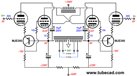
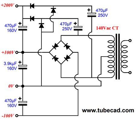
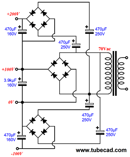
A center-tapped secondary is used and four output voltage result: -100V, 0V, +100V, and +200V. Note the capacitor voltage ratings and capacitance values. Only the output tubes will draw huge amounts of current, so only their connection needs to be to a large-valued capacitor. What about those folks that already own a conventional Circlotron, whose floating-power-supply secondaries are not center-tapped? The easy workaround is to use two extra rectifier bridges and six capacitors, as shown below. Magic. Three power-supply rails were there was one.
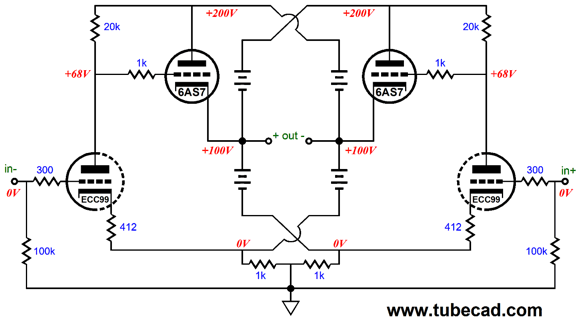
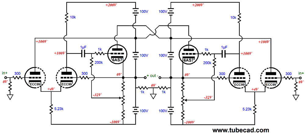
Okay, now that we have stretched and warmed up, we can move on to the following Circlotron circuit.
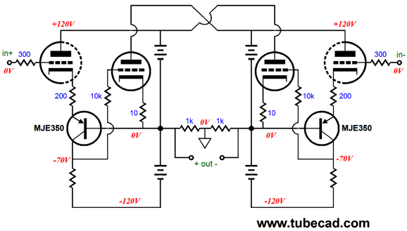
The large-valued coupling capacitor is gone and driver stage inputs are at ground level. (I love this Circlotron. In fact, so much so that I would like to have a 24 by 18 inch poster made of the schematic. Indeed, I will name this circuit the "Broskie Circlotron.") The driver stage consists of a cathode-coupled amplifier and its inverting input receives the negative feedback by its direct connection to the output. Note how both triodes in each cathode-coupled amplifier see the same plate voltage. Nice. I recommend working backwards, when trying to figure out how any power amplifier works. Imagine a car battery being quickly attached and then disconnected from the output terminals. Assuming that the battery's positive terminal attached at the positive output, the positive-voltage pulse would provoke a huge negative voltage swing from the cathode-coupled amplifier on the left, which would in turn force the left 6AS7 triode's grid negatively, reducing its conduction. At the same time, the negative-voltage pulse applied to the right side of the Circlotron, will force the right 6AS7 triode to conduct much more. The net effect would be that the output stage will fight hard against the imposed voltage pulse, which implies a low output impedance. If, on the other hand, we begin at the driver stage's inputs, the cathode-coupled amplifier do not invert their input signals, so a positive voltage presented at the left input will provoke a positive signal at the left 6AS7 triode's grid; a negative presented at the right input will provoke a negative signal at the right 6AS7 triode's grid. What is missing from the above schematic are some finishing touches, such as protection diodes, some power-supply filtering, 10-ohm cathode resistors for each 6AS7 triode's cathode... But what most readers will want to see is a suitable input stage to drive this unity-gain output stage.
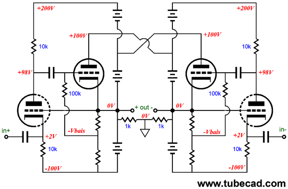
The idea behind this input stage is simple enough: a differential amplifier, but with an important difference. Note how the long-tail cathode resistors attach to both floating power supplies, as do the plate resistors. How can this work, when the power supplies move up and down in voltage with the output signal? Simple: the voltage movements are equal but out of phase, so the average remains the same, for example -70Vpk and -130Vpk for the bottom connections, which averages to -100Vdc. This means that the differential amplifier's common cathodes and separate plates never see the balanced power supply voltage movements. Sweet. Before anyone think about e-mailing me for a suggestion for the best input tube to use, I will say that the 12AX7 or 6072 or 12AT7 or 6N1P are probably good choices.
Next Time
//JRB
|
|
I know that some readers wish to avoid Patreon, so here is a PayPal button instead. Thanks.
John Broskie
E-mail from GlassWare customers:
And
High-quality, double-sided, extra thick, 2-oz traces, plated-through holes, dual sets of resistor pads and pads for two coupling capacitors. Stereo and mono, octal and 9-pin printed circuit boards available.  Aikido PCBs for as little as $20.40 http://glass-ware.stores.yahoo.net/ Only $12.95 TCJ My-Stock DB
Version 2 Improvements *User definable Download or CD ROM www.glass-ware.com |
||


| www.tubecad.com Copyright © 1999-2012 GlassWare All Rights Reserved |