| John Broskie's Guide to Tube Circuit Analysis & Design |
| Post 250 04 December 2012 Class-G Class-G Circlotron
The two batteries are merely placeholders for independent floating power supplies. And, of course, the triodes are not essential, as tetrodes, pentodes, FETs, MOSFETs, and transistors could be used in their place. The next issue I must deal with is What is class-G? Typical push-pull amplifiers, either tube or solid-state designs, can be run in class-A, class-AB, class-B, or class-C. The topology remains constant and only the idle current changes. These four classifications are based on percentages of operation each output device contributes to the output signal. In a class-A push-pull amplifier, neither output device ever turns off, each working over 100% of the output waveform. In a class-B push-pull amplifier, each output device idles at close to its cutoff and each works on 50% of the waveform; in other words, while one device works hard, the other cuts off. Class-AB push-pull amplifiers fall in between class-A and Class-B, each output device idles well above its cutoff and each works on a bit more than half the waveform at full output. Class-C is never used in audio amplifiers; well, at least not intentionally, as it distorts greatly. (Class-D is a different animal altogether, as the output device, almost always MOSFETs, produce square waves, not sine waves; in other words, the devices are either on or off, with no slow, smooth transition from one state to its opposite.) Class-G amplifiers return to the world linear, analog electronics with amplifier designs that look like more complex versions of typical push-pull amplifiers. The class-G amplifier's claim to fame is its increased efficiency, which is certainly better than the typical push-pull amplifier's, although not better than the class-D amplifier's. The following class-G output stage uses transistors for both driving the external load and for switching to the higher rail voltages.
(What is up with the gray background? I planned on covering class-G amplifiers long ago and I even drew up a bunch of schematics, but I never made the posting.)
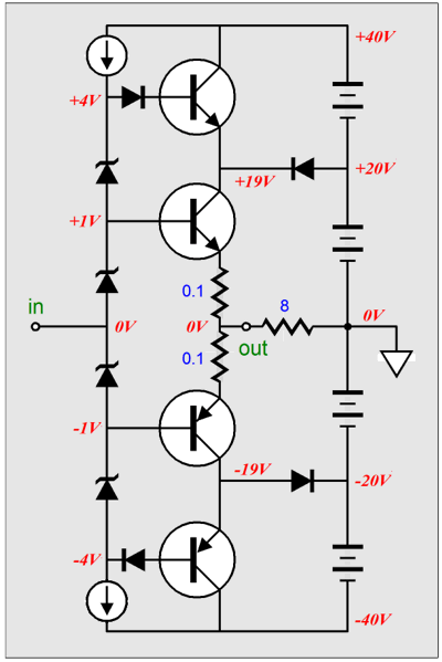
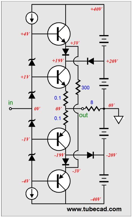
At idle, the two power transistors at the center of the circuit see fixed +/-19V power-supply rails, which will allow about 16W of output into an 8-ohm load (16Vpk). If more output voltage swing is required, the top and bottom power transistors are engaged and the rail voltages ramp up with the output signal, ending at almost double the +/-19V, allowing four times more wattage to be delivered into the speaker. Well, why not just use +/-40V rails and be done with it? Heat. Big rail voltages are great for creating output power, but they also create lots of wasted heat. Class-G topologies promise the low idle heat dissipation of a small power amplifier and the big power output of a large power amplifier. The best of both worlds? The unspoken assumption is that music, music that offers a wide dynamic range, is the signal source. Often this assumption is true, as most classical and acoustic music does go from soft to loud. Some music, on the other hand, doesn't; instead, it is relentlessly and uniformly loud. Moreover, recording studios love to apply a good amount of compression to the music signal, which renders it better suited for playback in cars or with iPods while jogging down noisy streets. In other words, limited-dynamics music and highly-compressed music makes class-G less compelling, while well-recorded naturally dynamic music, such as most classical and some jazz, is better suited to class-G, because of the music's huge dynamic range, which might require only 1W on average, but demand 100W peaks for realistic playback. Okay, returning to the actual design of a class-G output stage, the following is closer to what is actually made. The big difference this design holds over the previous design is that the power-supply transistors are driven by the output itself. If nothing else, this variation is a bit safer, as in the event of a dead short at the output, the output devices will not be also burdened by excessive rail voltage.
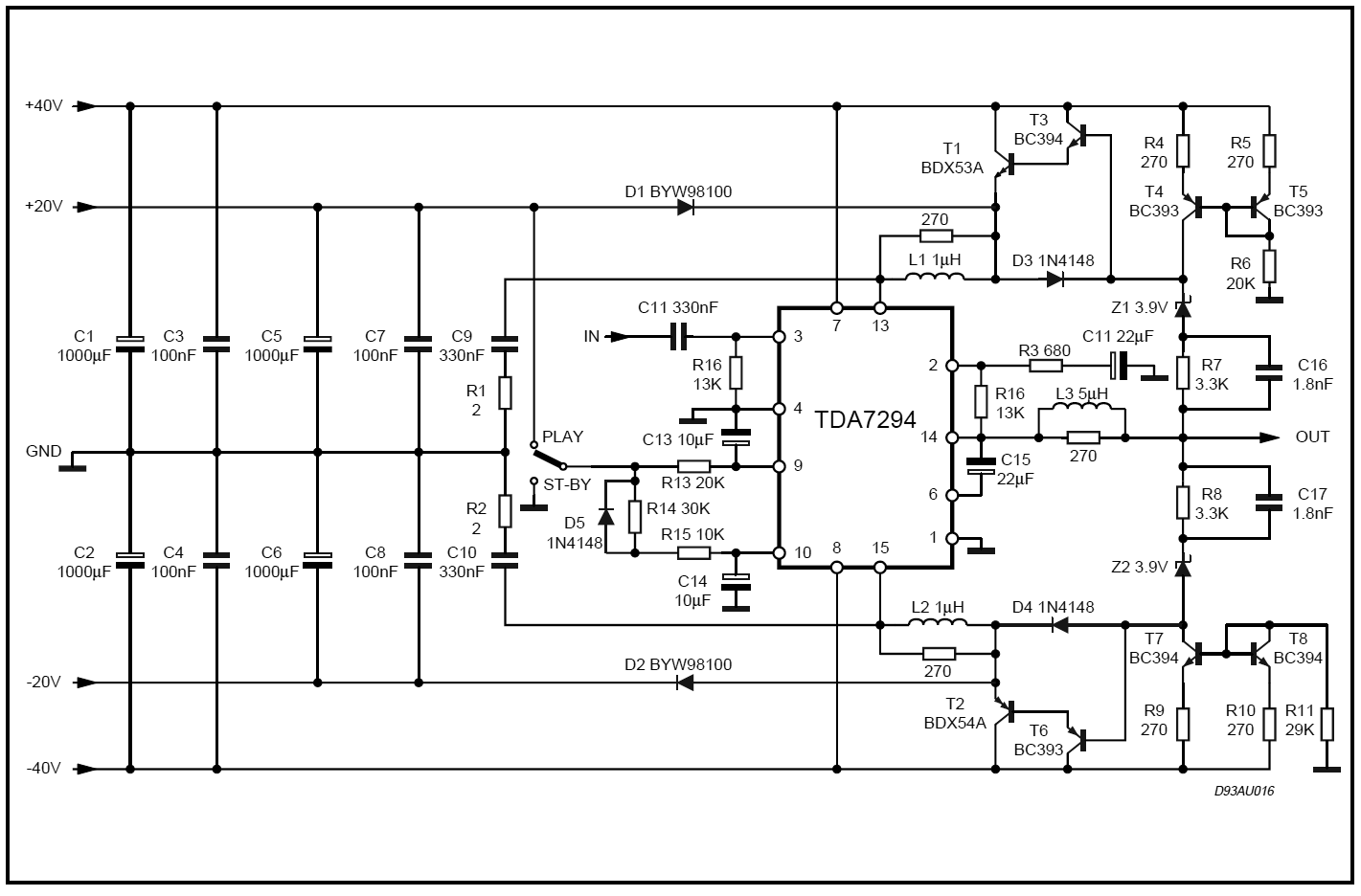
Nonetheless, the functioning remains the same, with the higher rail voltages only being engaged when needed. If you do not quite see how class-G amplifiers switch on their higher power supply voltages, go back to the above schematic and imagine the output voltage being 24Vpk and figure out all the resulting changes on voltages throughout the output stage. On the other hand, if class-G operation seems embarrassingly simple, move on to the following actual design example, which was taken from the data sheet for the TDA7294. (The TDA7294 is an extremely interesting power-IC amplifier that uses MOSFETs internally as output devices, not bipolar transistors, and which can deliver 100W.) Yes, this class-G design is much more complex.
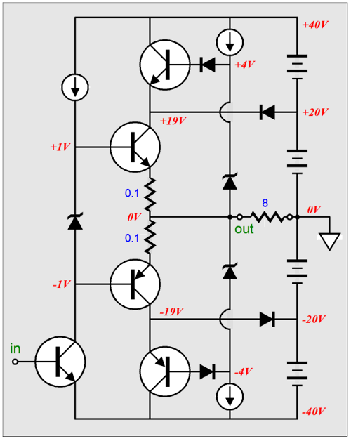
Note the Darlington power-supply transistors and the inductors (L1 & L2) and snubber circuits (R1, R2, C9, C10). Why are they there? When the power-supply transistors abruptly switch on and off they create oscillations that must be damped. My own workaround to the switching problem in class-G amplifiers was not to let the power-supply transistors ever turn off, as shown below.
The power-supply transistors no longer have a diode in series with their base, but their emitter does, which will entail the tiny loss in in efficiency due to the added diode voltage drops. In other words, a very good swap indeed.
Circlotron in Class-G
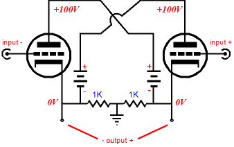
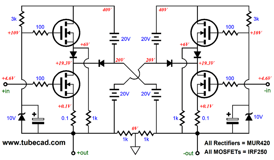
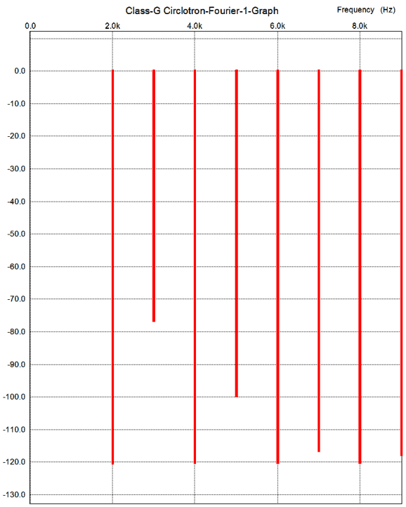
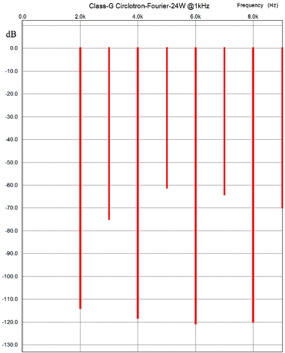
Although power triodes could be used, it is easier to see how this new variation on the Circlotron works with power MOSFETs. A balanced input signal is needed and output is taken at the bottom of the circuit. At idle, the two bottom N-channel MOSFETs see a fixed rail voltage of 19.3Vdc. Once the input signal peak voltage swing approaches the +/-19.3V rail limit, the top MOSFET power supply MOSFETs left the rail voltage above the 19.3V limit. Note the extremely high idle current for the two bottom MOSFETs, 1A (100mA is typically used). Why so high? This follows Douglass Self's scheme of running the output devices in class-A, since they will only see half of the potential drain-to-source voltage in a class-G amplifier. (Confusing as it might sound, a class-G amplifier can be run in class-A, class-AB, or class-B. These three classes all refer to idle current and load impedances, whereas class-G refers to a topological structure.) An idle current of 1A will yield up to 16W of class-A power into an 8-ohm load. (Of course, if you believe in unicorns or astrology, then you can pretend that all Circlotron amplifiers must run in class-A, as the glossy ads proclaim, and set the idle current to 10mA. If you are going to get free class-A, why pay anymore than 10mA?) The top power-supply MOSFETs never turn off, but draw a small trickle current through their 1k source resistors. Note where the 1k resistors terminate. . So how well does this Circlotron work? In SPICE simulations, I used the famous IRF250 MOSFET models and here is the distortion harmonics for 4W into 8-ohms at 1kHz.
The total harmonic distortion come in at less than 0.1%. If lateral MOSFETs were used in place of the output devices (the IRF250 could still be used in the power supply), no doubt lower distortion would result. At 24W of output, the following graph results.
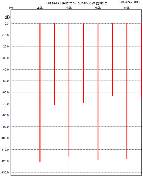
Considering that no negative feedback loop is employed and that the distortion hovers around 0.1%, the results are not bad. At 36W of output, the results look not that much different.
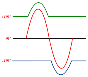
The power-supply rails track the output waveform at 36W nicely, as we see below.
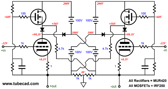
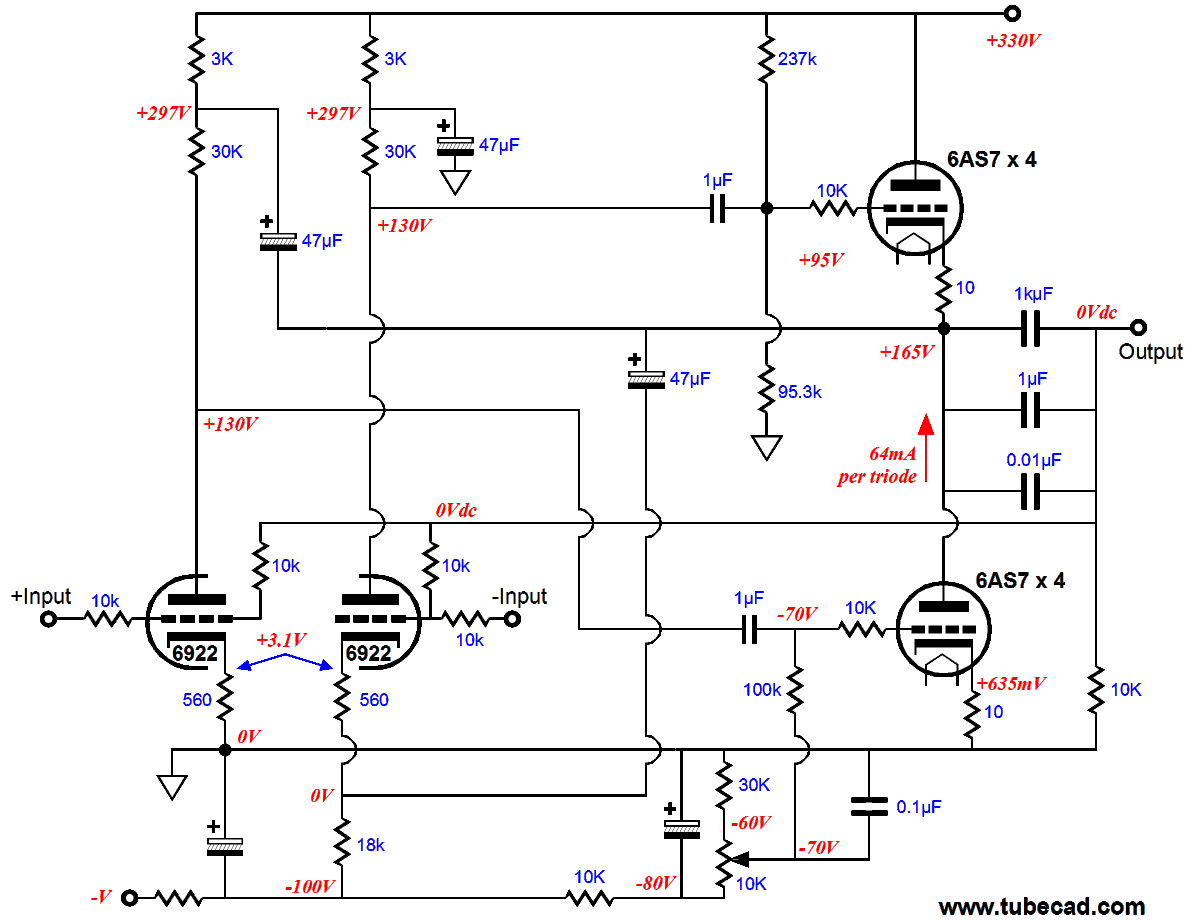
Since the frequency response plot is a ruler flat line from 10Hz to 100kHz, I won't bother showing it. The output impedance is less than a quarter of an ohm. The clipping performance was sweet, with softly rounded tops. Okay, John, this is all wonderful, but where the heck are the tubes? Well, we could use a tube-based input stage, making a fine hybrid amplifier or we could go the entire way and use beefy power triodes, such as the 6as& or 6C33. Setting up the fixed bias voltage would be a tad, only a tad, tricky. My bigger concern is that of the horrendous heat produced, as the power-supply triodes must be heated and must draw some current, else be subject to the dreaded tube sleeping sickness. A better solution might be to use high-voltage, N-channel, power MOSFETs with the tubes. The following circuit is intended for use with many 6AS7 triodes in parallel.
I haven't run SPICE simulations on the above circuit, but I bet it is close correct. Perhaps a better solution might be to use fixed high-voltage power-supplies for the triodes, but add a lower-voltage set of power supplies for two output transistors that are off at idle and then switch on, once the triodes run into current-delivery problems. A marketing department would refer to these current augmenting transistors as electronic turbochargers, but a better name would current limiters, as they strive to to impose a soft current limit on the triodes.
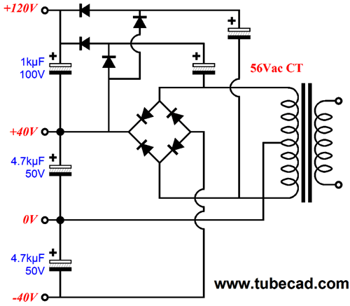
Although we might be able to get away with only one 6AS7 per channel, I would still use at least four per channel. Why? Heatsinks. It is much easier to keep many parallel transistors cool with many small heatsinks than two transistors with one big heatsink. Never forget that heat is the enemy of all solid-state devices. Yes, the three power-supply voltage, -40V & +40V & 120V, look like a real mess, but creating the three voltage is relatively easy. Below is an example of how three output voltage can be derived from a center-tapped 56VAC secondary. The bottom 4.7kµF power-supply capacitor could be replaced by a much smaller capacitor, say a 470µ/50V capacitor, as the negative rail is only used to provide a negative bias voltage for the triodes. Remember, two of the below circuits would be needed per channel.
On the other hand, if we were willing to introduce some iron, then we could use either a tapped choke or an output transformer, which would allows us to use ordinary output tubes such as the EL34, EL84, 2A3, 300B, KT88, KT100, KT120, 6550...
Circlotron & Iron
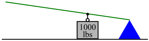
The first principle is that much like a lever and fulcrum, nothing is stolen or magically produced: power in is merely translated into a different form at the other side. This is the harsh world of physics, where free lunches do not exist*. In fact, the lever and fulcrum make a wonderful physical analogy to a transformer’s workings. Since most electronic folk think primarily in terms of voltage, we will start with voltage. You cannot lift 1,000 lbs of weight, but you can lift 100 lbs. If you place a lever over a fulcrum, ten feet of lever on your side and 1 foot of lever on the other side, you would be able to lift the 1,000 pound weight. For every 10 inches of movement on your side of the lever, the weight moves by 1 inch.
An output transformer that holds a winding ratio of 10 to 1 will perform a similar reduction of the primary voltage swings on its secondary. (The DC voltage on the primary side is ignored by the secondary.) For example, 100V of swing on the primary will result in 10V of swing on the secondary. In other words, the voltage ratio is equal to the winding ratio. Note that the slew rate—the measure the rate of change of the voltage swing and is usually expressed in units of V/µs—also follows the same ratio as voltage: the winding ratio. With the 10 : 1 winding ratio, the slew rate will decrease to a tenth on the secondary side.
An output transformer that holds a winding ratio of 10 to 1 will amplify the delta, the change in current flowing through the primary on its secondary. For example, swing of 100mA of current flow on the primary will result in 1A of current flow through the secondary. In other words, the current ratio is equal to the inverse of winding ratio; in this example, 1 : 10. Compared to solid-state output devices such as transistors and MOSFETs, tubes can only conduct embarrassingly small trickles of current. If loudspeakers presented 1kohm impedances, the tube’s wimpy current flow would not be a problem. But in a world filled with 4-ohm speakers, however, it is a huge problem, a problem that the output transformer solves quite well.
In terms of power, an output transformer strives to achieve a perfect translation, so the power in equals the power out. A primary voltage swing of 100V with a current swing of 100mA equals a secondary voltage swing of 10V with a current swing of 1A. Of course, real output transformers are made from real materials, such as wire that offers resistance and magnetic cores that suffer from eddy currents and other magnetic loses. The result is that we never achieve a perfect translation; instead, we always get less power at the secondary than we put into the primary. If the output transformer is a good design, the loss will be fairly small. Far too many tube-lovers only know about an output transformer’s impedance ratio, not understanding how it is related to the transformer’s winding ratio. An output transformer that holds a winding ratio of 10 to 1 will reflect 100 times the impedance presented at its secondary to its primary. In other words, the impedance ratio is equal to the winding ratio squared. If the winding ratio is 20 : 1, then the impedance ratio will be 400 : 1.
Now, let’s imagine a long lever that terminates on the tip of the fulcrum, with the weight attached towards the end, a class-2 lever & fulcrum in other words. Why? This arrangement is a closer analogy to a tapped inductor.
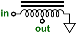
Although a tapped inductor does not provide the electrical isolation that a transformer offers, it nonetheless performs a similar function: translating power by reducing voltage swing, while increasing current swing and greatly magnifying reflected impedance. A center-tapped inductor is a good place to begin.
The center-tap appears at 50% of the inductor’s coil. Thus, a 10V voltage swing at one end of the inductor will create a 5V swing at the center-tap; a 1A current swing at one end of the inductor will create a 2A swing at the center-tap. So what will be the impedance ratio with this center-tapped inductor? Not 2 : 1, but 2² : 1 (or 4 : 1). So, if we attach an 4-ohm load across the center-tap and the other end of the inductor, the reflected impedance at the other end will be 16 ohms.
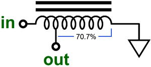
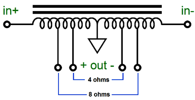
If we wanted to reflect 8 ohms with a 4-ohm load, then the tap would appear at the 70.7% point along the coil’s length. Such a tapped-inductor would always double the attached load impedance at the input end of the inductor, as the square root of 0.707 is 0.5; and as the impedance ratio of the tapped-inductor is equal to the inverse of square root of the tapped point; thus, the impedance ratio of this tapped-inductor is 2 : 1. A tapped-inductor suitable for use with a Circlotron power amplifier should hold at least five tapped points along the winding. The 50% tap is a convenient place to attach the ground.
Before going any further, I will mention something that most tube-lovers seldom consider: the added safety of using a tapped-inductor. Everyone knows that an output transformer is vastly safer than an OTL power amplifier that is directly coupled at its output, as the output transformer cannot pass DC current from its primary to its secondary. A catastrophic meltdown within an OTL’s power tube can short the plate to the cathode and your expensive speaker will be welded to the B+ voltage! If the same catastrophe occurred with an output transformer, your speaker would be safe. Well, what about a tapped-inductor? What happens in a Circlotron with the same catastrophic meltdown of one power tube? A perfect inductor presents zero resistance, so would displace no voltage, no matter how high the DC current flow through it. Real inductors do represent some DC resistance (DCR), depending on the thickness of the wire used. If the tapped-inductor is physically large enough, the DCR can be quite low, say only 0.1 ohms. Well, shorting an 8-ohm loudspeaker with 0.1-ohm resistor is highly effective in protecting the speaker. In fact, it is probably as good as using a large coupling capacitor. Remember, we need to protect the speaker only long enough for the power-supply fuses to blow and the power-supply capacitors to discharge. Okay, let’s add some tubes to the Circlotron with a tapped-inductor. Which tubes? They could the usual OTL types, such as the 6AS7, 6C33, PL509… or the usual audio power tubes, such as the 2A3, 300B, or EL34 & EL84.
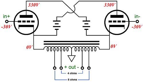
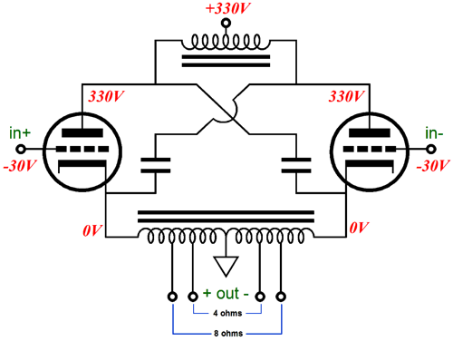
Once again, the batteries are not batteries, but only placeholders for floating power supplies. (Treat the batteries as being dead shorts with a large voltage drop.) At idle, no current flows through the tapped-inductor, as no voltage differential exists between its leads. As the output tubes push and pull, swing up and down in voltage, the tapped-inductor sees the produced current flow and delivers it to the loudspeaker. Simple enough. But if look at the inductor’s center-tap, we see that it is located at the null in voltage swings, never moving of zero volts. Well, what if we add a center-tapped inductor to top of the circuit?
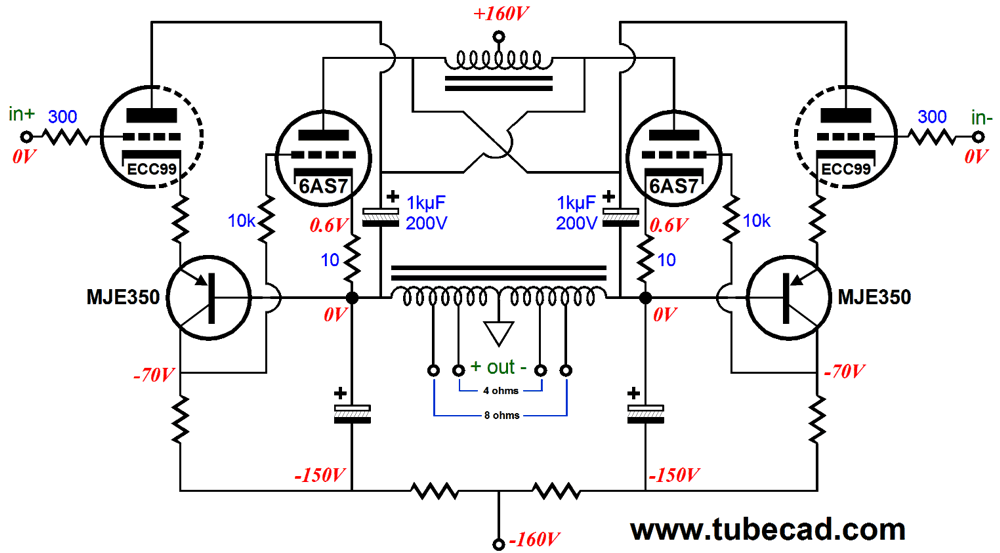
The batteries are gone, which means that the two floating power supplies are gone (four floating power supplies for a stereo power amplifier) and a single high-voltage power supply can be used. Wonderful. I have covered this arrangement many times before, but I know that many do not understand how it could work. The secret is to focus on the two power-supply capacitors, not the center-tapped inductor at the B+. Those two capacitors tightly couple the load impedance to the output tubes’ plates and cathodes and are very much in the signal path. As one output triode cuts off, ceasing to conduct, effectively dropping out of the circuit, the other triode completes a circuit with its capacitor and the load resistance. (This had lead some down the foolish path of believing that the Circlotron is in effect a single-ended amplifier. It’s not. It is a push-pull amplifier through and through. Just look at the distortion harmonic signatures in the above graphs and tell me if they look like those created by a single-ended amplifier.) I will end with a lower-voltage version. The following Circlotron output stage uses two PNP transistors to create an inverted cascode circuit with the driver tubes. Note the DC coupling, which would scare me silly if it weren't for the tapped-inductor there to protect the speaker. The 10-ohm cathode resistor is rather essential, as it prevents current runaways by the output tubes. Speaking of output tubes, I would use three or four 6AS7s per channel. Four 6AS7s (a total of eight triodes) per channel would deliver at least 60W with a tapped-inductor that presented a 32-ohm impedance from lead to lead. Why so much more wattage than usual, as many more 6AS7 are usually required? The 32-ohm load is a much more optimal load impedance.
Click on schematic for enlargement
Broskie OTL
Next Time
* Unfortunately, electronics is bound by the strict and unrelenting laws of physics. Other endeavors are not so constrained. For example in Keynesian macroeconomics, there is a fantastic outcome known as the Multiplier Effect. And what an effect it is! Here is how it works: I force you to give me $1,000, which I then give to your neighbor. He is overjoyed and likes me lot, which is important, as he will be on my side if you get all indignant. He also quickly spends his free money on a new big flat-screen TV. I know that it sounds like you were just robbed for no good reason, but believe me there is a great reason. The $1,000 gets multiplied by the economy, so the $1,000 effectively becomes $2,000 to $4,000 after it changes many hands. Awesome, no? I remember reading somewhere that the US government uses a multiplier of six in its calculations. Now just imagine how wonderful it would be if we put 10W into an output transformer's primary and got 60W out on the secondary! That would be far better than perpetual motion. Sure, some might complain that if you had been allowed to keep your $1,000, you could have bought the same TV. These people just don't get it. First, your neighbor didn't actually get the full $1,000, as there is the overhead and administration costs, so he only got $900. But this seemingly lost and wasted $100 actually receives the same multiplier effect, so the economy grows by something closer to $600 just due the $100. In addition, your neighbor, as you would be the first to admit, is something of a slacker, so he just rushes out and spends his free $900 on the first expensive and shiny thing he sees—it was free money after all. You, on the other hand, are far too parsimonious and far too careful in your purchases, so you would search out the best deal—it is your money after all—which undermines the multiplier effect. Worse still, you might leave your $1,000 in savings, which can only damage the economy. No multiplier effect, no recovery. If the Multiplier Effect still doesn't make sense, just remember that Loss is Gain, Destruction is Production, Borrowing is Income, Theft is Justice, Ignorance is Strength, Nonsense is Wisdom, and Descent is Forward. Of course, there are few, very few, economists who query the validity—indeed the very existence—of the multiplier effect. One is the Harvard economist, Robert Barro, who insanely believes that the multiplier effect is less than one! Less than one, which would mean that we would get less rather than more. How did he go so very wrong? I believe an answer can be found in the fact that, prior to getting a Ph.D. in economics, he graduated with a B. S. in physics from the California Institute of Technology. Sure, in physics, the multiplier effect would be ridiculed, being seen as insanely illogical, but then physicists are bound by those strict and unrelenting laws.
//JRB |
I know that some readers wish to avoid Patreon, so here is a PayPal button instead. Thanks.
John Broskie
E-mail from GlassWare Customers
High-quality, double-sided, extra thick, 2-oz traces, plated-through holes, dual sets of resistor pads and pads for two coupling capacitors. Stereo and mono, octal and 9-pin printed circuit boards available.  Aikido PCBs for as little as $24 http://glass-ware.stores.yahoo.net/
Support the Tube CAD Journal & get an extremely powerful push-pull tube-amplifier simulator for TCJ Push-Pull Calculator
TCJ PPC Version 2 Improvements Rebuilt simulation engine *User definable
Download or CD ROM For more information, please visit our Web site : To purchase, please visit our Yahoo Store: |
|||


| www.tubecad.com Copyright © 1999-2012 GlassWare All Rights Reserved |