| John Broskie's Guide to Tube Circuit Analysis & Design |
Post 252 29 December 2012  Tune Up Tune Up Circlotron Tune Up Time An example from the world of tube audio is the false quote often attributed to me that the Circlotron circuit is identical to the Futterman totem-pole design. It is not; nor have I ever said that it was. Thus, the need for a tune-up of sorts, an effort to get us all on the same page, as it were. But first some history behind my false quote. Almost a decade ago I wrote and posted here an article that I titled “Cars, Planes, and Circlotrons,” wherein the following introduction appeared.
Well, my guess is that was as far as many readers got before committing my essay to the flames and, thus, was born the false quote, which I get repeated to me in e-mails countless times. So, let me set things straight: the Futterman design is different from the Circlotron. Different, not because of a bipolar power supply or the totem-pole output tubes or a large coupling capacitor, but because of where the ground falls, where the amplifier’s signal reference is located within the circuit. But first, let's do a quick recap, starting with the Circlotron.
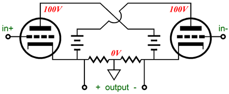
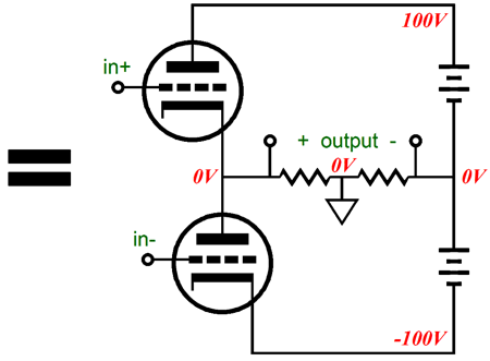
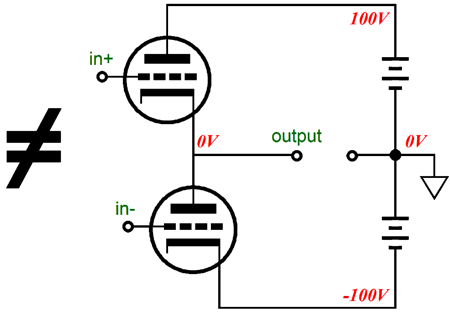
The two high-voltage batteries are not true batteries but symbols for two floating, high-voltage power supplies. What does “floating” mean? It means that no part of the power supply directly attaches to ground, the circuit’s signal reference. In the Circlotron circuit, the ground is found in between the two 1k resistors that span the two outputs. (Betraying some of the magical thinking behind the Circlotron circuit, in homebuilt and commercial Circlotron amplifiers, is the use of two huge, 25w or bigger, power resistors, where 1W-to-3W 1k resistors would suffice.) The basic six parts of the Circlotron, the two triodes and two resistors and two power supplies, can be differently arranged, yet deliver the same functionality and performance. For example, the following circuit is the electrical equivalent to the Circlotron, appearances to the contrary.
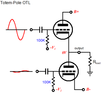
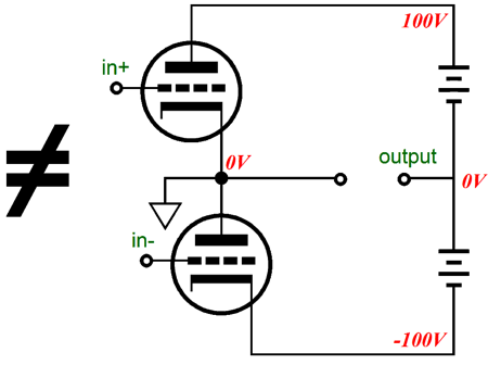
Caught you, Mr. Platinum Brain, that is the famous Futterman OTL amplifier, so you are saying that the Circlotron is identical. No, no, and again no. This is not the Futterman totem-pole configuration. Note where the ground lies: not at the right at of the circuit at the midpoint between the two floating power supplies, but in between the two 1k resistors. Does that make a difference? Indeed, yes, all the difference in the world. Had the ground been located between the two power supplies, the two output tubes would require dissimilar input signal, with the top triode getting a vastly larger input signal than the bottom triode, as the output is taken at the top triode’s cathode, so the cathode moves in sync with the top triode’s grid.
Note how the bottom triode's grid sees a much smaller input signal comapered to the top triode's grid. But since the top triode's cathode follows the grid, the two output tubes end up seeing the magantude of input signal relative to thier cathodes.
But as the ground is located between the two 1k resistors in the totem-pole equal to the Circlotron, each output tube sees an input signal equal in magnitude, differing only in phase relative to ground and thier cathodes, just as does the basic circlotron. Additionally, the output impedance is higher in the totem-pole equal to the Circlotron due to the ground not appearing at the power supplies nexus. Therefore, the Circlotron does not equal the following totem-pole circuit, the basis for what is found in the Futterman.
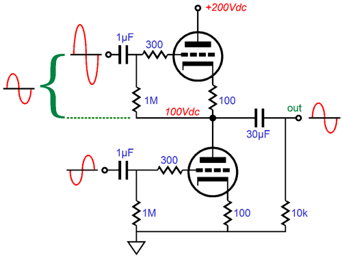
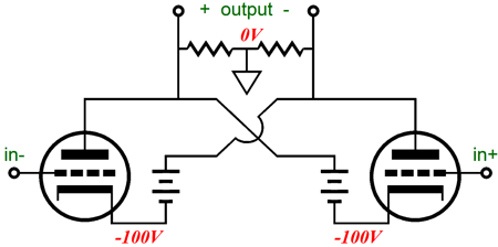
Do not make the mistake in believing that the disqualifying aspect of the above circuit is that the power supplies are no longer floating relative to ground, as the following circuit also is not the equivalent to the Circlotron, although its power supplies are floating.
This circuit is a brother to the Futterman totem-pole, as the two output tubes require dissimilar input signals, but this time the bottom triode getting a the larger input signal than the top triode, as the output is effectively taken at the bottom triode’s cathode, as the bottom triode’s cathode moves in sync with the output signal. Lastly, we should look at a Circlotron equivalent that should be much easier to understand. Since the two floating power supplies are effectively dead shorts in AC terms, the output can be taken at the plates, rather than at the cathodes.
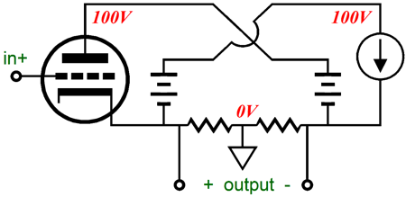
By the way, a widely-circulating mistake is to imagine that the floating power supplies are not in the audio signals path. They are—very much so. This can readily be proved in SPICE simulations, where it is easy to track the current flows through the circuit and the load. My guess is that this assumption (the power supplies are not in signal path) comes from the false belief that Circlotron is by necessity of its topology a class-A design*, so all the current that flows through the speaker also flows equally through the two output tubes, never through the floating power supplies. This is plainly wrong, as equal current flow between tubes would equal zero flow through the speaker, as like all push-pull amplifiers, it is the delta, the difference in current flow between the two output tubes that is delivered into the load; no delta, no signal. Perhaps, if we look at a true single-ended version of the Circlotron (many falsely believe that the Circlotron is a dual-single-ended amplifier, which is pure madness), we will more readily see how the power supplies complete the current path through the speaker.
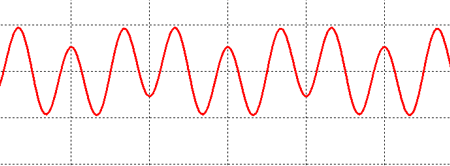
The constant-current source matches the current draw from the triode, so no DC offset occurs. The variation in current flow through the triode creates a varying voltage across the speaker, which induces a varying current flow through the loudspeaker, creating the music we hear. The only way the triode’s varying current flow can run through the loudspeaker is through the floating power supplies, which means that they are in the signal path. (By the way, the constant-current source's floating power supply can be much smaller in value, if a solid-state CCS is used.) Or, we can try this SPICE/thought experiment, wherein the floating power supplies in a conventional Circlotron present two different power-supply noise frequencies, say 100Hz and 300Hz, due to each power supply seeing a different AC frequency on its primary, 50Hz and 150Hz. If the power supplies are not in the signal path, then neither frequency should appear on the output, in the absence of an input signal. Well, as the following SPICE simulation graph shows, the two frequencies are present; therefore the power supplies are in the signal path.
Why does power-supply noise normally not appear at the Circlotron’s output? The Circlotron is a balanced, push-pull circuit, so as long as the two triodes are conducting equally, which they do at idle, and as long as the power supplies hold identical power-supply noise, both in amplitude and frequency, the power-supply noise nulls at the output. If the power-supply noise differs in either amplitude or frequency, the perfect null will not obtain. If one triode ceases to conduct, which it will once the output signal goes over a 1w or so, the power-supply noise will become superimposed on the audio signal. I can readily hear this and I labeled this phenomena dynamically-induced poor PSRR. I believe this is one reason why single-ended amplifier can sound so much cleaner than most push-pull amplifiers. Well, that ends today's tune up. I have to go throw some snowballs.
Next Time
* As I understand it, this claim also comes in a different flavor: the 6AS7 tubes never completely cut off, so the amplifier is a class-A amplifier; now, leave me alone! Interesting. This is less a supporting argument than it is a damning indictment of the 6AS7, as it proclaims that the triode is such a poor, sloppy effort that it, much like a leaky faucet or a drooling idiot, never completely turns off, as it always trickles a dribble of current. Well, fine. Class-F tubes equals class-A amplifiers. But if this is true, in only some lame legalistic sense, then the Futterman can readily be transformed into a class-A amplifier by switching to slipshod tubes, such as the 6AS7 or remote-cutoff pentodes. (Of course, the negative feedback loop would have to be severed, as one of its jobs is to ensure that slovenly tubes cutoff when they are required to cease conducting.) The biggest failing of such an argument is that betrays a fundamental confusion on the actual, true, and desired benefits from honest class-A, push-pull operation, which requires robust idle currents that must at least equal half of the peak output current and meaningful current flow contributions from both output tubes, not gooey drippings of current.
//JRB |
I know that some readers wish to avoid Patreon, so here is a PayPal button instead. Thanks.
John Broskie
And
High-quality, double-sided, extra thick, 2-oz traces, plated-through holes, dual sets of resistor pads and pads for two coupling capacitors. Stereo and mono, octal and 9-pin printed circuit boards available.
Designed by John Broskie & Made in USA Aikido PCBs for as little as $24 http://glass-ware.stores.yahoo.net/
The Tube CAD Journal's first companion program, TCJ Filter Design lets you design a filter or crossover (passive, OpAmp or tube) without having to check out thick textbooks from the library and without having to breakout the scientific calculator. This program's goal is to provide a quick and easy display not only of the frequency response, but also of the resistor and capacitor values for a passive and active filters and crossovers. TCJ Filter Design is easy to use, but not lightweight, holding over 60 different filter topologies and up to four filter alignments: While the program's main concern is active filters, solid-state and tube, it also does passive filters. In fact, it can be used to calculate passive crossovers for use with speakers by entering 8 ohms as the terminating resistance. Click on the image below to see the full screen capture.
Tube crossovers are a major part of this program; both buffered and un-buffered tube based filters along with mono-polar and bipolar power supply topologies are covered. Available on a CD-ROM and a downloadable version (4 Megabytes). |
|||


| www.tubecad.com Copyright © 1999-2012 GlassWare All Rights Reserved |