- Hardcover: 246 pages
- Publisher: Wem Publishing (October 13, 2010)
- Language: English
- ISBN-10: 0956154514
- ISBN-13: 978-0956154514
- Product Dimensions: 9.1 x 6.3 x 1.1 inches
| John Broskie's Guide to Tube Circuit Analysis & Design |
|
Post 227 07 April 2012
Essential Book: Designing Power Supplies for Tube Amplifiers Mr. Blencowe knows who his DIY readers are and what their hopes and expectations are. He knows that most solder-slinging audiophiles stumble when it comes to designing and building a power supply for their project. He also knows that the audio circuitry makes different demands on a power supply and that tube audio makes extra demands, because of higher voltages involved. He knows that finding such information is difficult, as the average power-supply book is intended for a different audience. Thus, his book wisely ignores switching power supplies, but generously covers tube rectification, series and shunt regulation, and heater power supplies. Nor is his book merely a historical summery, as many many tube-amplifier books tend to be, covering only old designs that your grandfather would recognize. Instead, Designing Power Supplies for Tube Amplifiers summarizes existing tube-audio power supplies, but also reveals new techniques and designs. Be warned, you will encounter many formulas in Designing Power Supplies for Tube Amplifiers, but do not worry, as only simple algebra is required. In addition, all the many schematics are cleanly laid out and easy to understand. (So far, I haven't found a single schematic typo, which is a laudatory achievement indeed.) And the book's layout is good, comprising ten chapters, the first chapter covering power transformers and the last, voltage control (input AC voltage control). One oddity is finding what should have been the eleventh chapter (Cooling and Heatsinking) nested in chapter seven, "Series Voltage Stabilizers." Are not the topics of cooling and heatsinking also applicable to shunt stabilizers or to unregulated power supplies? In fact, it was only in reading his explanation of calculating heatsink requirements that my eyebrows began to knit, my forehead furrowed. For example, although he praises silicon thermal pads, so much tidier, he says nothing about the up to 1.5°C/W thermal resistance they add. Indeed, I don't see this hefty resistance in the long string of thermal resistances that he lists in the calculations for determining the heatsink's required minimum thermal resistance, pages 129 & 130. Instead, I was surprised to see him give 0.1°C/W thermal resistance as the average case-to-sink thermal resistance; surely, that was a typo and he meant to write 1°C/W. (The Elliott Sound Practices web site offers wonderful heatsinking explication, guidelines, and design practices .) In spite of the word "tube" in the book's title, I instantly assumed that Mr. Blencowe was a Brit, not just because his first name is Merlin. Under the dust jacket, the book's spine and its inner title page reveal the book's true title, Designing Power Supplies for Valve Amplifiers. Moreover, Mr. Blencowe writes like a Brit, abundantly displaying good manners, never lapsing into excessive informality (deferential, glad to be of use, politic, cautious, and meticulous...). Do not get me wrong here, as I greatly prefer such a style over the "Hey Dude, pass me the roach, I mean alligator clip" style of many guitar amplifier books. Still, for this American, Mr. Blencowe's over reliance on a somewhat passive and circumlocutory exposition wearies. For example, he begins a section titled "Relative output voltages of rectifier circuits" thus:
After the first hundred pages, I felt like slapping him on the back and telling him, "Just spit it out man" and I am a rabid anglophile. As I read the above paragraph, my mind translated it into American thus:
Perhaps, I am making a Maugham out of a molehill, (you know, Somerset Maugham) as few readers are likely to read this book in a single sitting (as I did) and his prose is still far more spritely and readable than any modern electronics textbook I have read—and I have read plenty. (The luminous exception being The Art of Electronics by Paul Horowitz and Winfield Hill, a fantastically good electronics textbook and well worth the $100 price tag; be sure to get the 1989 second edition. In general, electronics textbooks written before 1960 are lucidly and gracefully composed. The urge to make some snide comment on the modern educational system was almost impossible to resist, such as: How could so much have been achieved without a Department of Education, establish in 1979? Fortunately, I held firm...or did I?) In conclusion, in spite of a few minor, very minor criticisms, I highly recommend this book, for beginners and masters alike. Beginners should read the first five chapters over and over again, as they cover essential material, such as transformer selection, rectification, and filtering; particularly, the chapter on LC smoothing filters, as most tube fans know nothing about the problem of LC resonance. Advanced practitioners will find much to like in these and in the following five chapters. Many pure tube-based and solid-state-based and hybrid solutions are illustrated; there is even a quite Janus-like shunt regulator that utilizes both feedforward and feedback to produce clean, steady DC voltage, page 124 ;) And the last chapter is a must read, as it covers the problem of too little or too much wall voltage and some possible solutions. Today, however, it is not enough that a book be well written, illustrated, researched, and organized, as it must pass the new test, the web test: If I can find all the same material on the web for free, do I really need to buy this book? In the case of, Designing Power Supplies for Valve Amplifiers, the answer is yes, you need the book, as you cannot find it all on the web; no doubt, many portions can be found, but not everything—and certainly not in such a well packaged format. Additionally, you can put your trust in Mr. Blencowe's efforts. Can you say that about all that you find in a Google search? One last comment, this book is also available at Antique Electronic Sales for a slightly higher price ($1.01 more) than at Amazon.com...but if you need some other tube supplies, throwing in a copy of this book makes a lot of sense.
New HV Regulator Topology
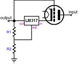
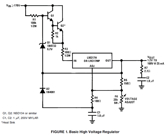
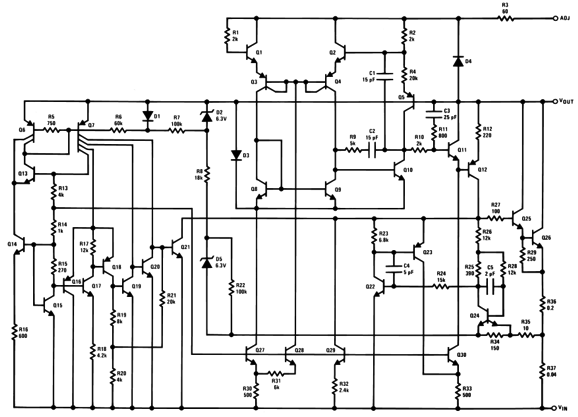
The low-voltage regulator establishes and maintains the fixed output voltage, while the high-voltage triode shields the solid-state device from lethal voltages. The LM317 strives to maintain a constant 1.25Vdc difference between its output and adjust pins, with the output being more positive than the adjust input. If the high voltage regulator’s output falls below its design goal, the adjust input effectively becomes more positive relative to the output, causing the LM317 to increase its conduction, pulling the output up in voltage until the 1.25Vdc relationship is reestablished. On the other hand, if the regulator’s output climbs above its target voltage, the adjust input now effectively becomes more negative relative to the output, causing the LM317 to decrease its conduction, dropping the output voltage until the 1.25Vdc relationship is once again reestablished. As tubes grew ever less popular in sober electronics, this circuit was expunged from later data sheets. In its stead, the following high-voltage regulator appeared in National Semiconductor’s Linear Brief LB-47: High Voltage Adjustable Power Supplies.
The single triode had been replaced by two high-voltage transistors and some extra support circuitry. The design functioning remained the same: the LM317 was safely ensconced within a small voltage window, yet it controlled the high voltage regulator’s output. Well, all of this is old hat. What intrigued me was this question, Is it possible to make a high voltage regulator based on an LM337? No, not a high-voltage negative regulator, which would be merely a mirror image of the above circuit, with PNP transistors replacing NPN types, my goal was a positive high-voltage regulator. No one asked me this question; I was just giving myself a brain teaser. My first thoughts were that it would certainly be possible to create a shunt regulator, such as the following.
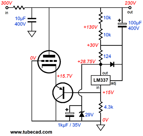
Where to start? This high-voltage shunt regulator looks far more complex than it really is. The LM337 is in control, measuring the output voltage and applying corrections as needed. Two critical parts are the 29V zener and 1kµF capacitor; without these parts the regulator would not regulate. In other words, they are not safety devices the way the unmarked diode is (1N4007) in the schematic. The zener both establishes a fixed reference voltage and a current path in parallel with the LM337. The voltage drop across the zener is added to the voltage drop across the string of resistors (10k, 10k, 124) atop the LM337’s output. The LM337 will use all its considerable negative feedback to keep a steady 1.25Vdc across the 124-ohm resistor, which in turn will ensure a constant-current flow through the resistor string, establishing a fixed voltage drop the resistor string. If the high voltage shunt regulator’s output voltage rises, the LM337 will see the increased voltage at its adjustment pin and reduce its conduction, which will decrease the voltage drop across the 4.3k resistor, forcing the PNP transistor’s emitter climb down in voltage, provoking a greater conduction of current by the triode, as its grid becomes effectively more positive relative to its cathode, pulling the high-voltage shunt regulator’s output voltage down. Conversely, should the high-voltage shunt regulator’s output fall in voltage, the LM337 increases it current conduction, thereby decreasing the triode’s, resulting in a pulling up of the regulator’s output voltage. In other words, the LM337 is constantly evaluating the voltage it sees at its output and adjustment pins, as it strives to maintain a fixed voltage difference between the two. The LM337 really doesn't know that it is the heart of an elaborate high-voltage positive regulator; all it knows is what is happening at its output and adjustment pins. Thus, we must overlay two critical signal sources on top of these two pins: the high-voltage regulator’s output and ground. Ground? Ground isn't a signal source. Actually, in a voltage regulator, it is THE signal source, as a voltage regulator can be viewed as being a powerful unity-gain amplifier, with a huge fixed DC offset and whose signal source is ground. This is why the 1kµF capacitor is critical; it couples and relays the ground to the LM337’s output pin. The weaker and dirtier the AC connection to ground, the worse the high-voltage regulator’s performance will be. The same holds true for the connection between the LM337’s adjustment pin and the high-voltage regulator’s output, so the 100µF capacitor is also critical. Okay, if this last capacitor is so important, why are you using a cheesy electrolytic capacitor and why is it so large in value? If this capacitor only terminated into the LM337’s adjustment pin, it could be replaced with a small-valued film capacitor. But the capacitor also terminates into the 124-ohm resistor, which is effectively grounded at its other end. When we plug 124-ohms and 100µF into the following formula, we get 13Hz as the -3dB cut-off frequency. Frequency = 159155/R/C Why not use even higher-valued resistors in the resistor string, so a 1µF capacitor can be used, say a hundred time larger? We can, but the trickle of current flow into the LM337’s adjustment pin (about 65µA) will become a bigger factor in establishing the desired output voltage. In other words, a $140, super-audiophile-grade, 0.22µF Teflon capacitor will not cut it. One workaround is to use much higher-valued resistors (ten times greater) in the resistor string, which will allow using a 10µF film capacitor. Of course, this would also greatly reduce the current flow through both the zener and the LM337 negative voltage regulator. Not good. But if we place a power resistor(s) in parallel with the resistor string, the LM337 and zener can still get the current they require.
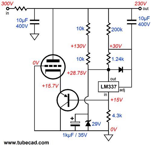
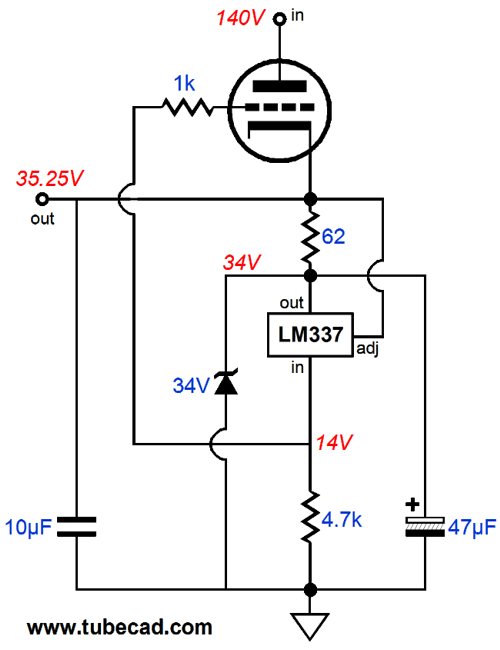
Another issue is the limited amount of possible voltage swing that the shunting triode’s cathode can see with the 29V zener. National Semiconductor makes (or used to make) a high-voltage version of the LM337, which can withstand 47V between its input and output pins. This would buy us a 17V bigger voltage window in which to operate the LM337 and control the triode’s cathode voltage. Unfortunately, the LM337-HV doesn't come in the TO-220 device package, only the TO-3 and TO-39 packages. In addition, our shunting triode might require even greater potential cathode swings. The following variation uses a bipolar power supply and “grounds” the LM337’s output, so the 1kµF electrolytic capacitor is no longer needed. This is the baby-step circuit before we move on the actual circuit; nonetheless, it might prove adequate for many preamp and line-stage amplifier applications. (Although the negative bias voltage tap is usually only found on big power transformers that were intended for use in tube power amplifiers.) The big difference between this variation and the previous circuit is that the shunting triode’s cathode is no long being driven; instead, its grid voltage is varied. The PNP transistor has been replaced by the NPN transistor, which inverts the phase of the voltage signal developed across the 100-ohms resistor in series with the LM337’s input pin.
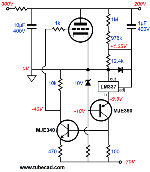
Now we arrive. The following variation uses a PNP transistor to cascode the LM337, so it operates in a 9.3Vdc voltage window, but transmits the LM337’s current-flow variations to the 100-ohm resistor in series with the MJE350’s collector, which in turn drive the MJE340's base.
Note the staggeringly high valued resistors in the resistor string the LM337 uses to establish the desired output voltage and the correspondingly low-valued capacitor that relays the high-voltage regulator’s perturbations on its output to the LM337’s adjustment pin. Next, we move on to the series high-voltage regulator based on the LM337.
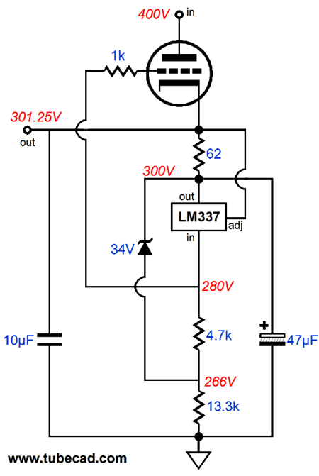
New Series High-Voltage Regulator
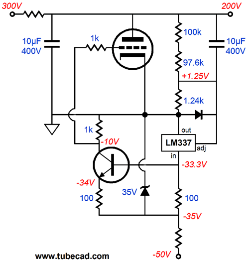
If the high-voltage series regulator’s output voltage climbs too high, the LM337’s adjustment pin will climb with it, making the voltage differential to great between its adjustment and output pins, which will prompt a decrease in the LM337’s current conduction, causing the triode’s grid to fall in voltage, reducing its conduction, thereby bringing the regulator’s output voltage back in line. Note that a 1.25Vdc across the 62-ohm sense resistor implies a current flow equal 1.25/62, or about 20mA. At idle, with no external load, the triode and the 13.3k resistor see a 20mA current flow, while the zener and the LM337 share the 20mA between themselves. In the schematic, the LM337 conducts 3mA, while the zener conducts 17mA. With an external load attached, the triode might undergo a current flow of 100mA, while the 13.3k resistor still sees the steady 20mA and the LM337 may 17mA and the zener 3mA. As it stands, this high-voltage series regulator is interesting, but it is a bit naked and it offers limited grid-voltage swings. The following deluxe version addresses both of these concerns.
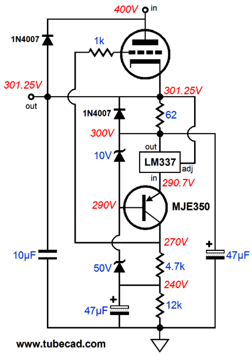
Yes, it looks complicated, but the operation is the same. The two 1N4007 diodes are safety devices that allow the 10µF and 47µF capacitors a discharge path at turn off and protect the LM337 in the case of the high-voltage series regulator’s output being shorted to ground. The two zener diodes provide an alternative current path to the LM337 and provide a base voltage for the MJE350, which cascodes with the LM337, shielding the LM337 from high voltages, yet relaying the LM337’s current conduction variations to the 4.7k resistor. By the way, the LM337 only sees a 9.3V voltage differential across its output and input pins and a maximum current conduction of about 18mA. Thus, its maximum power dissipation is only 0.17W, so no heatsink is required on it. Likewise, the MJE350 never dissipates much heat, so it also can be run naked. The 12k resistor, on the other hand, will get plenty hot, as power dissipation equals I²R, which I this example equals 4.8W. I would use either a 10W resistor or two 5W 24k resistor in parallel. A warning:
The Safe Approach
Next Time
//JRB |
|
I know that some readers wish to avoid Patreon, so here is a PayPal button instead. Thanks.
John Broskie
E-mail from GlassWare customers:
And
High-quality, double-sided, extra thick, 2-oz traces, plated-through holes, dual sets of resistor pads and pads for two coupling capacitors. Stereo and mono, octal and 9-pin printed circuit boards available.  Aikido PCBs for as little as $20.40 http://glass-ware.stores.yahoo.net/ Only $12.95 TCJ My-Stock DB
Version 2 Improvements *User definable Download or CD ROM www.glass-ware.com |
||


| www.tubecad.com Copyright © 1999-2012 GlassWare All Rights Reserved |