| John Broskie's Guide to Tube Circuit Analysis & Design |
| Post 226 26 March 2012
Yes, it's been a painfully long time. So much sand has poured down the hour—or is it month—glass that I do not know where to begin. The shipment of PCBs did arrive in February, a tad late and a bunch overpriced. I am now paying twice as much as what I paid a few years ago. In other words, I am searching again for a new PCB production house. I seem to be detecting a pattern: the first order always cost below what I would expect, and then each subsequent order goes up 15%. This is probably a winning business model, as few are willing to jump to another PCB maker, which would entail establishing new contacts and figuring out the new PCB producer's quirks and demands. One problem I keep running into is the expectation that I only want one PCB design to be made, not 20 different ones. The second odd stumbling block is that most PCB makers have a minimum charge per PCB, which might start at $8. Obviously, not all PCBs are equal in surface area or in number of holes and I would make little sense for me to buy a PCB for $8 and then add a $3 rotary switch and sell the two for $8, which is the price I charge for many of my small PCBs. But this headache is a constant one. The new headache was my computer dying about two weeks ago. I keep three backups of the data I create, a backup external hard drive, a hard drive in a safety deposit box, and a web-based back-up service. What I didn't back up was my e-mail or my dozens of passwords. Big mistake. Next time I will be ready. I bought a new Dell and I love it, as is fantastically quiet (and also fast). I broke down and got one with Windows 7, the 64-bit version, installed. Well, now, half of my best-loved software dosen’t work, including many that I created, so I am on a software buying spree—to replace what I already owned (and often preferred to the new improved version). For example, my beloved Igrafx Designer technical illustration program now longer worked. Not good, as I have over 20 years’ worth of schematics and all my user guides stored in its unique file format. Fortunately, CorelDRAW can import the files, with a quite a bit of tweaking and hair pulling. 
The CorelDRAW Graphics Suite X6 is actually quite impressive, feature rich as they say in the ads. What follows will quickly dispel any notion that I might have gotten a free review copy from Corel. CorelDRAW can certainly do everything that I want it to do, but just not as easily or quickly as I want. I was spoiled by Micrografx (later Igrafx) Designer. I know there is always a steep learning curve with any regal piece of software, such as Photoshop or AutoCAD, but I have already owned and used CorelDRAW 3, 6, and 9, so I am already fairly high up on its learning curve. And no doubt, after a year or so, I will have attained truly dizzying heights on that curve. Nonetheless, I know that it will take me much longer to draw a complex schematic than it did on my 13-year-old Designer. I used to have a friend in Silicon Valley who worked as freelance technical writer and technical illustrator. He also loved Designer; so much so that he stipulated in all his hiring contracts that he would be allowed to use Micrografx Designer—exclusively, or forget it. Another friend who worked in the electronics field always used Micrografx Designer, but never told anyone. He would be given a huge two-page exploded illustration to draw and he would ask to be allowed to go home, where he would encounter no distractions, to draw the drawing. After a few few hours, he would be done and then he exported the drawing in the AutoCAD file format. Since he was expected to take at least a full day or two to complete the drawing with AutoCAD, he didn’t return to work until the next day or maybe the day after. And I remember the time that I helped a friend draw a simple schematic in AutoCAD and I was horrified to see how labor intensive the simple job was under AutoCAD. And he was not stuck low on the learning curve, as he spent his entire work day using AutoCAD, drawing airplane engine parts. Do not misunderstand me here: I believe that AutoCAD is a fantastic program and it can do many things that my old Micrografx Designer could never do. I am just saying that it is too unwieldy for something as simple as drawing a decent electronic schematic. My last holdup was that this web site is at its limits, both in size and bandwidth. (As I write this, I have no idea if I will be able to post it.) It has used up the space allotted on the server and it is getting over 2 million hits a month (and touching cloth in terms of bandwidth). I have made arrangements with my web hosting company to move the site to a bigger, and I hope faster, server. It hasn’t happened yet, but soon. Speaking of web hits, how many e-mails do you imagine piled up during the four-day computer outage? I am of course speaking about good e-mail, not lurid spam, but three-times filtered e-mail. Fasten your seatbelt, 1505, about a half of which had to be read and about a fourth of which had to be answered. The situation is actually a bit worse than that, as I was setting a new password and making renewed connections to my ISP, much like the sea giving up its dead, about 80 old e-mails surfaced into my mailbox. These were all e-mails that were in response to e-mails that I had instigated. I thought something was queer when I would offer free test equipment and electronic parts to friends and then never get an answer. In addition, friends would ask if I got their recently-sent e-mail and no search yielded a positive result. Well, they were there trapped in the e-mail account that my ISP forced me to have. Odd, very odd, as I downloaded e-mail from the account everyday, but these 80 were trapped in e-mail limbo. I could add to the my list of woes spring break and my beloved kids being home all day and my having to do my taxes, but why bother, when a dead computer is enough tragedy for anyone.
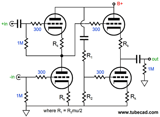
Water Under the Bridge Well, all of this got me interested in playing with stereo summing and difference circuits again; you know, the old L+R and L-R circuits for the glory days of quadraphonics. So, I set upon seeing how to implement these electronic functions with tube circuitry and my first efforts were producing far too complex topologies that required far too many tubes. Then it hit me: only two triodes were needed and I had come up with the circuit 20 years ago and wrote an article on the circuit here 12 years ago titled, Design Idea: (L+R) & (L-R) in One Stage. The circuit uses the single current path shared by two triode in totem-pole arrangement to perform the jobs of adding both left and right channels together and subtracting the right channel signal from the left channel's signal. Here is the schematic from the March 2000 article:
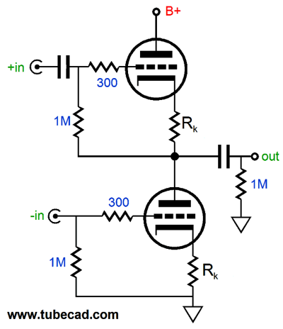
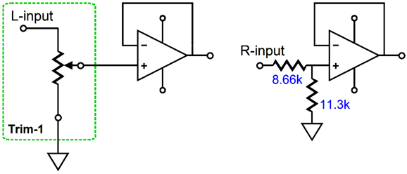
I won't recap how this circuit works, as the article does a good job of that, but I will show you the optimal resistors values that I uncovered during several SPICE simulations of the circuit: 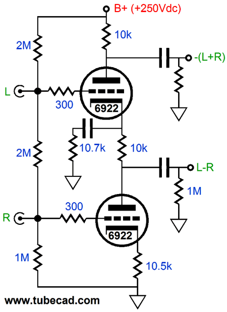 By the way, this circuit can readily be reduced to just a differential amplifier, a Vertical Diff Amp:
Its CMRR (common-mode rejection ratio) is stellar and its PSRR equals roughly 1/mu. The distortion can be reduced by increasing the cathode resistor values and slicker, more Aikido circuit, can be had by adding an Aikido cathode follower.
With the Aikido cathode follower, the CMRR and PSRR can easily reach -60dB.
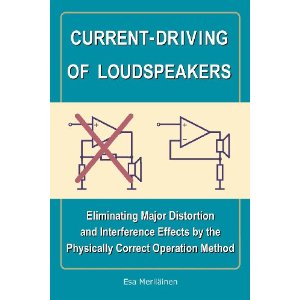
Current-Output Amplifiers
Just how is it amazing? His book is a 6" x 9" soft cover, with 342 pages that is beautifully made. All the schematics, drawing, graphs, and formulas are splendidly precise and clean; the book covers both theory and practice. He answers many of the questions I had and he has sent me back on to the path of current-drive amplification with renewed enthusiasm. This book will be controversial, as it compels a 180 degree rethink, which 99% of people are loath to do, which is why Nicolaus Copernicus very wisely had his famous book, De revolutionibus orbium coelestium, published posthumously. I will give a longer, true book review when I am done reading it. Here is the table of contents, which certainly reveals how deeply Mr. Meriläinen digs into the topic of driving speakers with current rather than voltage. Contents of the book
APPENDIXES
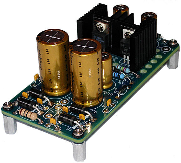
New Bipolar Low-Voltage Regulator
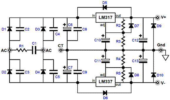
I have been playing with OpAmps lately and I needed a small bipolar low-voltage regulator that would fit in small boxes that were too small for my big B-PS-1. Besides I just fell in love with the heatsink I used, as it holds two TO-220 devices. Of course, this heatsink cannot compete with the two big, 2.5in tall, 2.7C heatsinks used on the B-PS-1, but many OpAmp circuits do not demand a high current draw. The PCB is 2.2in by 4.5in big and the heatsink is only 1in tall. The PS-12's schematic shows how simple the circuit is. The parts used are fancy, not the circuit. An LM317 positive and LM337 negative regulator are used to establish the bipolar output voltages. It can deliver any voltage between +/-5V to +/-24V by selecting different values for resistors R3 & R4.
ThePS-12 bipolar regulator kit is available at the GlassWare-Yahoo store.
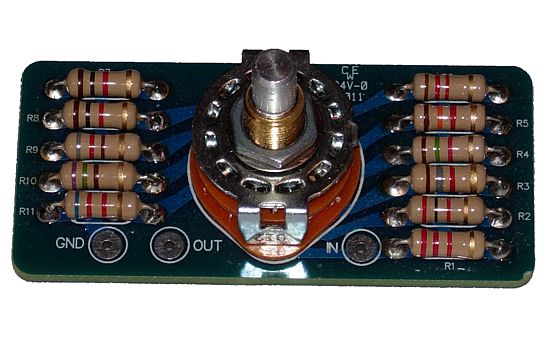
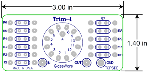
11-Position Stepped AttenuatorThe Trim-1 single-channel, stepped attenuator offers 11 positions and can viewed as high-quality replacement for a potentiometer.
In other words, it can be used in non-audio as well as audio applications. Making a linear potentiometer replacement is easy: just divide the require resistance by 11 to get each resistor's value. For example, if a 100k potentiometer replacement is needed, use 9.09k 1% resistors or 9.1k 5% resistors. If ½W resistors are used, then the dissipation limit for the Trim-1 would be 5.5W, as 11 x 0.5W = 5.5W. Why would anyone want an 11-position linear potentiometer? I can think of my possibilities, such as in a HV variable voltage regulator, where the Trim-1 could be used to set the output voltage in 25V steps. 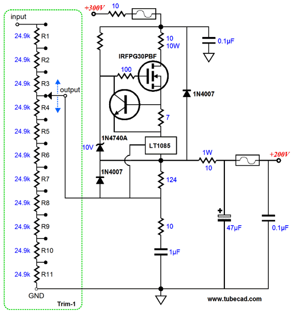
Or, two Trim-1 stepped attenuators could be used, one for fine 5V steps and one for coarse 50V steps. Or, a Trim-1 could be used to set the negative bias voltage for an output tube, situated between two series resistors. For audio use, however, a log taper is desired. The amount of attenuation per step depends on the application. For example, if one Trim-1 is used per monobloc power amplifier, say as a volume-matching control in a bi-amplifier setup, where the tweeter or midrange is a few dB more efficient than the woofer, then -1dB (or -0.5dB) decrements are suitable. (Many feedback-free tube amplifiers present a slight gain mismatch between channels, as the tubes are not perfectly matched; thus, -0.5dB decrements are useful.) On the other hand, if dual mono volume controls is the intended application, then -6dB decrements are a better choice. A Trim-1 can be used as a balance control, by using -1dB steps and using only one in the left channel and using a -5dB two-resistor fixed attenuator on the right channel. Then turn the Trim-1 to its sixth position (-5dB), so the channels match.
I am sure that you can think of many more uses for this little stepped attenuator, as can I. For example, in an electronic crossover, so each output could be adjusted. Or, the crossover frequencies themselves could be selected.
The Trim-1 is available now at the GlassWare Yahoo store.
Next Time
//JRB |
I know that some readers wish to avoid Patreon, so here is a PayPal button instead. Thanks.
John Broskie
E-mail from GlassWare Customers
High-quality, double-sided, extra thick, 2-oz traces, plated-through holes, dual sets of resistor pads and pads for two coupling capacitors. Stereo and mono, octal and 9-pin printed circuit boards available.  Aikido PCBs for as little as $24 http://glass-ware.stores.yahoo.net/
Support the Tube CAD Journal & get an extremely powerful push-pull tube-amplifier simulator for TCJ Push-Pull Calculator
TCJ PPC Version 2 Improvements Rebuilt simulation engine *User definable
Download or CD ROM For more information, please visit our Web site : To purchase, please visit our Yahoo Store: |
||||||||||||||||||||||||||||||||||||||||||||||||||||||||||||||||||||||||


| www.tubecad.com Copyright © 1999-2012 GlassWare All Rights Reserved |