| John Broskie's Guide to Tube Circuit Analysis & Design |
Post 203 22 March 2011
Unbalancer
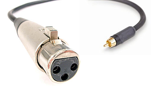
Behold the the Unbalancer: a tube-based, balanced-to-unbalanced converter that accepts a balanced input signal and puts out a single-ended, unbalanced signal, much like a Broskie cathode follower, but with gain. (In fact, a Broskie cathode follower is the output stage in the Unbalancer circuit.)
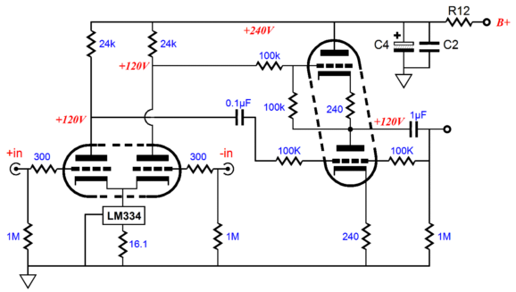
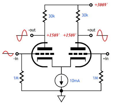
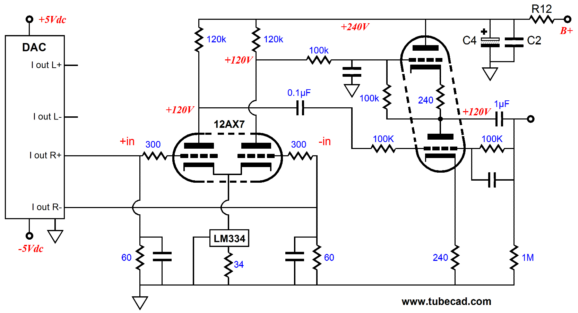
The input stage is a differential amplifier with a constant-current source load on the coupled cathodes. Besides performing its unbalancing conversion, the Unbalancer circuit provides voltage gain and exhibits a fine CMRR (Common Mode Rejection Ratio), which means that the Unbalancer largely ignores common-mode signals. In other words, it delivers what a good balanced circuit should deliver.
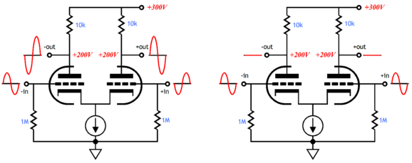
The differential amplifier works by presenting each grid with a signal equal in amplitude, but inverted in phase relative to the other grid. This arrangement results in one triode drawing greater current and the other less current. To the degree that the two triodes are matched, the net effect will be a an unvarying constant current flow through the total circuit. If the current does not vary through the cathode resistor, nor will the voltage across it vary, which means that the cathode voltage should remain fixed. Thus whatever anti-phase, balanced voltage is presented to both triodes’ grids won’t be mitigated by degeneration at the cathode of each triode, which means more gain—the same amount as a grounded-cathode amplifier would yield with the same triode and plate load resistor and with no cathode resistor (or with a bypassed cathode resistor). On the other hand, a common-mode signal presented simultaneously to both grids will result in a slight change in the current flowing through the cathode resistor, which will cause the cathode voltage to follow the grid voltages, thus greatly reducing the gain at the output. Hence, the name “Differential Amplifier.” This circuit amplifies the differences in grid signals and largely ignores what is common to both grids. Moreover, in the Unbalancer circuit, the differential input stage sees a constant-current source at its coupled cathodes, which allows the circuit to even better ignore common-mode signals and automatically sets the desired cathode-bias voltage for input triodes. The LM334 only requires one resistor to set its idle current. (The constant-current source can be left off the PCB, with the differential amplifier using simply a single common cathode resistor.)
If a signal is presented to only input triode, the other triode's grid being grounded, the Unbalancer will nonetheless amplify the unbalanced input signal with a gain equal to half of what a balanced input signal would achieve. The distortion is still amazingly low and the PSRR is still exceptionally fine. With a GlassWare phase selector switch, it would be quite easy to throw the unbalanced input signal to one grid or the other, making phase inversion an option.
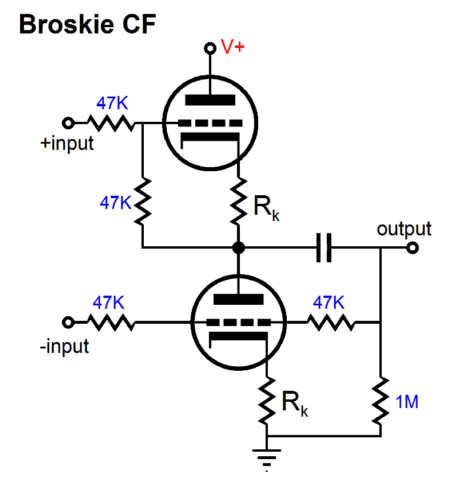
The Broskie cathode follower receives a balanced input signal from the differential amplifier and converts it to an unbalanced output. It is a unity-gain buffer (actually a gain of 0.5, so the two phases added together equal 1) that offers a high input impedance, low output impedance, low distortion, and great CMRR. In addition, because the Broskie cathode follower uses a push-pull topology, its use is not limited to line-stages, as the Broskie cathode follower can be used as a headphone buffer-amplifier if the headphone's impedance is high enough (say, 300-ohms). In addition, much like a signal transformer, the Broskie cathode follower offers a good common-mode signal rejection (CMRR); this means that Broskie cathode follower easily passes a differential input signal, but ignores what is common to both input signals. Why is this a feature? Common-mode signals are extraneous to the actual input signal and usually consist of hum, power-supply noise, and RFI. In other words, in the Unbalancer, we have cascaded two circuits that that offer high CMRR figures, the differential amplifier and the Broskie cathode follower.
All-in-One Design A low-voltage Unbalancer could be made with 6DJ8/6922 tubes and raw B+ voltage of only 170Vdc, which after the two RC filters would result in a final B+ voltage of 150Vdc. Such as setup could use a 120Vac power transformer for the B+ voltage and a 12.6Vac transformer for the heater power supply portion. With two power transformers, a staggered AC power-on switch could be used, wherein the heaters are energized first and then the B+ voltage comes on.
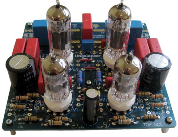
My Own Unbalancer Project
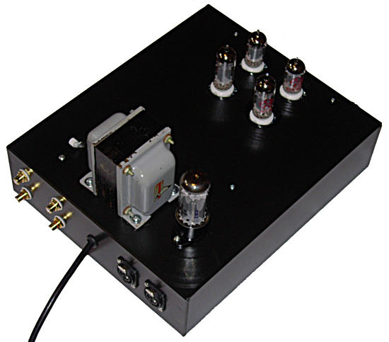
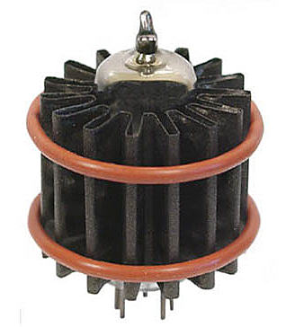
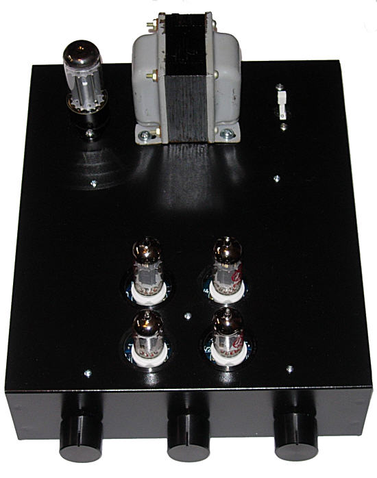
I mounted all the parts, except the tube sockets, on the bottom of the PCB, so the tubes could protrude from the chassis top. (Since taking the photos of my unbalancer, I have added PEARL Coolers to all four tubes, which not only dissipate heat, extending the tube life, but seem to dampen the tube envelopes, letting even more sonic detail flow forth. I now use PEARL Coolers on all my tube gear.)
Note the tube rectifier; the interesting question is, Does the Unbalancer require a tube rectifier? No, as the PCB uses solid-state rectifiers. So what is the tube rectifier doing there? I added a 5Y3 rectifier to my project to make use of the transformer's extra 5Vac winding. The 5Y3 is thus used as slow-turn-on resistor, not a rectifier.
The tube rectifier comes in between two high-voltage, power-supply 47µF/450V capacitors, in place of resistor R17. I like this setup a great deal, as the slow turn-on results in a smoother start up.
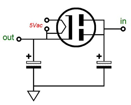
I used the JJ ECC802 and ECC99 tubes in my Unbalancer. The resulting gain is perfect for my setup and I truly like the sound from these tubes. (Other tubes that would work well are the 6AQ8, 6CG7, 6DJ8, 6H30, 12AT7, 12BH7, 5963.) In fact, I quite like the sound from my Unbalancer, but at first I wasn't so pleased. Once it was up and running, I was immediately struck by how the sonic image was no longer as wide as it had been with the Tetra and old LPs. But as I listened, I realized that the center image was supremely well focused and that the imaging depth was easily twice as deep as provided by the LPs. Then the more I thought about, I understood what was going on, how many of the the 50 and 60s jazz albums I had been playing for weeks all shared a fake super stereo quality, a form of dueling mono, which was common back in the beginning days of stereo, as customers wanted to hear extreme stereoeveryone wants to get his money's worth after all. Still, something was definitely missing. At first, I had floated the ground connection from the DacMagic—purposely, as I am very nervous about ground loops. Well, it is a testament to the soundness of balanced circuitry that the hum level was only a moderate little buzz, considering that about 60Vac separated the two grounds. Now, with with my DacMagic and Unbalancer grounds tightly connected, the hum is completely dead and buried below the power amplifier's residual 1mV of hiss. More importantly, the Unbalancer's image instantly grew much wider and more spacious. I love it. For example, I heard subtle details on familiar CDs that I have never heard before, in spite of hundreds of listenings Another good feature the Unbalancer offers is that my inclination is now to turn down the volume, rather than cranking it up; there's just no need to force detail to the surface by blasting the sound. (My wife, kids, and neighbors are most pleased.) It's been almost two months since first firing up the Unbalancer and I still love it. I am surprised by this, as I am often become disappointed by what initially pleased me most. Thus, I was suspicious when I found myself liking the Unbalancer's sound so much. So, I waited to to be disappointed, but I never was. Beyond sounding good in its own right, the Unbalancer allows me to better exploit my DAC. Exploit? I am convinced that by taking the DacMagic's output signal from its balanced outputs is the only way to go, as it eliminates at least one OpAmp from the signal path. Below is an example of how many post-DAC analog circuits are setup, with the balanced output being taken right after the two parallel OpAmps. In other words, we get to skip the final summing OpAmp, which converts the balanced signal to an unbalanced output.
Was there nothing that I didn't like? At times, I have felt that its sound might be too HiFi or possibly tad too bright, but with other recordings I instantly change my mind. (In many ways, the sound is much like electrostatic headphone listening: good recordings sound fabulous; bad recordings sound bad.) In the future, I might change the coupling capacitors, but that is the only modification I see myself making now—I rather listen to music than solder. In fact, I have been going through my library in search of sonic treasures that have hitherto remained hidden. For example, in general, I am not a big fan of Telarc recordings (preferring the sonics from such labels as BIS and Harmonia Mundi), but I have to admit that some of Telarc's offerings are just amazing sounding with the Unbalancer in place. No, the bass isn't any deeper or louder; it's more along the lines that the room ambience and instrument intonation is more readily heard now. For example, the Telarc recording of Arvo Pärt's Fratres is truly fine.
For the last 22 years I have loved Pärt's music, which is reflected in my owning about 40 CDs of his music. I find his music glorious and mesmerizing. And this recording beautifully reveals more of what is so magical about Pärt's music. His compositions are often described as post-minimalist. And with such spare, lean music, every note counts and on this Telarc recording each note is clearly sounded. Another CD that impressed me greatly was Blues Singer by Buddy Guy.
Buddy Guy is an amazing electric guitar bluesman, but on this CD, he is playing purely acoustic and he is singing in an old 1920-1930s country-blues fashion. I don't believe this CD is generally known in audiophile land, but it should be, as it is beautifully recorded, a HiFi demonstration grade recording. Buddy Guy has made many, many albums over the years, probably close to 100, so it is easy for one CD to get lost in the array, but this one is a must have. Here is what one reviewer at Amazon said:
Unbalancer as I-to-V Converter
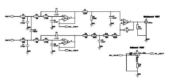
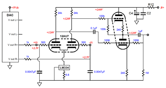
The 60-ohm resistors can be shunted with small-valued capacitors to impose a simple low-pass filtering, say 0.1µF. A second low-pass filter could be added to the Broskie-cathode-follower portion of the Unbalancer circuit, as shown below.
Alternatively, a balanced voltage-out DAC could be used. Often these type of DACs present a large DC offset at their voltage outputs (roughly half the DAC's B+ voltage), which will cause no harm to the Unbalancer, because of the LM334 constant current source will simply adjust to the DC voltage at the coupled cathodes to match. (Note the simple post filtering; of course, something much more elaborate can be implemented.)
Unbalancer PCB & Kit
Next Time //JRB |
I know that some readers wish to avoid Patreon, so here is a PayPal button instead. Thanks.
John Broskie
And
High-quality, double-sided, extra thick, 2-oz traces, plated-through holes, dual sets of resistor pads and pads for two coupling capacitors. Stereo and mono, octal and 9-pin printed circuit boards available.
Designed by John Broskie & Made in USA Aikido PCBs for as little as $24 http://glass-ware.stores.yahoo.net/
The Tube CAD Journal's first companion program, TCJ Filter Design lets you design a filter or crossover (passive, OpAmp or tube) without having to check out thick textbooks from the library and without having to breakout the scientific calculator. This program's goal is to provide a quick and easy display not only of the frequency response, but also of the resistor and capacitor values for a passive and active filters and crossovers. TCJ Filter Design is easy to use, but not lightweight, holding over 60 different filter topologies and up to four filter alignments: While the program’s main concern is active filters, solid-state and tube, it also does passive filters. In fact, it can be used to calculate passive crossovers for use with speakers by entering 8 ohms as the terminating resistance. Click on the image below to see the full screen capture.
Tube crossovers are a major part of this program; both buffered and un-buffered tube based filters along with mono-polar and bipolar power supply topologies are covered. Available on a CD-ROM and a downloadable version (4 Megabytes). Download or CD ROM
|
|||


| www.tubecad.com Copyright © 1999-2011 GlassWare All Rights Reserved |