| John Broskie's Guide to Tube Circuit Analysis & Design |
POst 210 13 August 2011
RIP Allen Wright It seems that I am always the last to hear of the death of famous audio folk. I remember John Atwood calling me to tell me that Dr. Gizmo (Harvey Rosenberg) had died. I could not believe it, as I had just had a long telephone conversation with him two days earlier. I was also startled when I heard that Charlie Kittleson, editor of Vacuum Tube Valley magazine, had committed suicide months ago. I had dinner with him about a year prior and we had been e-mailing a bit afterwards. (I was pushing him in the direction of resurrecting his magazine, albeit as an online effort.) He seemed to me, at the time, to be more tired than depressed. At 55 years old, I can expect a lot more bad news in the coming years, as ours is a hobby for old men, at least here in America.
Something New: MP3 of Blog Post
Cathode Bias with a Constant Current Source Nonetheless, I am reminded of all those readers who wrote about a decade ago to explain how the circlotron was actually two single-ended amplifiers working in parallel. My answer was that, in that case, all push-pull amplifiers (such as Dynaco ST-70 and the Futterman OTL amplifiers) were also two single-ended amplifiers working in parallel. The test is if the two tubes work in anti-current phase to each other or in phase. If in phase, then the amplifier is a parallel single-ended (PSE) design. If out of phase, then the amplifier is a push-pull design. It's really that simple. Iout = Ia - Ib Before moving on to how this auto-bias method works in a push-pull amplifier, let's look into why this technique is never used in a single-ended amplifier.
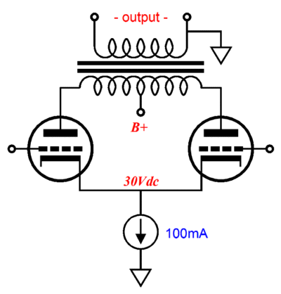
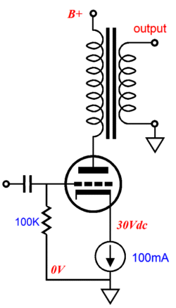
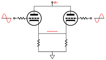
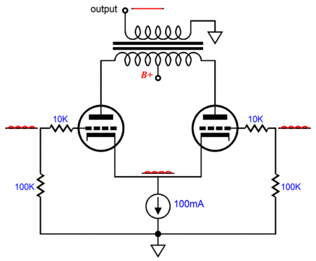
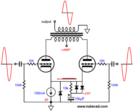
In the above circuit, everything seems to be kosher. The constant-current source sets the required cathode-bias voltage and the idle current remains steady, in spite of an inflating or deflating B+ voltage. But that is just the problem: the current remains too constant. An output transformer relays a variation in current flow through its primary to its secondary. No change in current, no output signal.
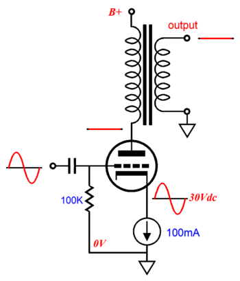
Any attempt to the get some output signal into the speaker—by applying a input signal to the grid—will be countered by the constant-current source. The grid goes up, the cathode goes up; the grid goes down, the cathode goes down. The workaround is to place a whopping big capacitor across the constant-current source, which will effectively "ground" the cathode to AC signals, allowing the amplifier to amplify. In sharp contrast, a push-pull amplifier that uses an unbypassed constant-current source can amplify. Why? The quick answer is that the connected cathodes do not move.
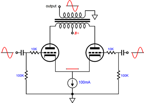
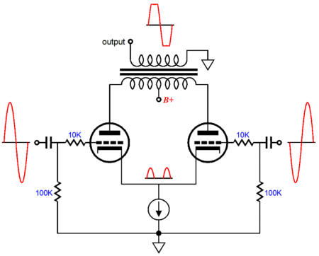
As long as the two tubes are working within the class-A envelope, which is set by the idle current and the load impedance, the voltage at the connection to the cathodes remains almost constant. (As no tube is perfectly linear, there will be small voltage wiggles on the cathodes.) Think about it this way: in a cathode-follower circuit, the cathode tries to follow the grid; thus, if the grid moves up in voltage, the cathode follows the upward movement. Now what would happen if two cathode followers were placed in opposition to each other, with one trying to pull up, while the other tried to pull down?
If the tube were the same and both saw the same input signal (albeit inverted for one cathode follower's grid), then the result would be a tie, with the connected cathodes remaining fixed. Well, that is what is happening with the push-pull amplifier that uses an unbypassed constant-current source. Okay, so we have arrived—or have we? This is the perfect tube output stage, right? (I was trying here to recapture some of the breathless quality that those e-mails from days past held when asking about this auto-bias technique for a push-pull output stage.) As long-time readers know all too well, none of these questions admits a simple, pure, absolute yes-or-no answer. The historical reason the constant-current-source cathode load isn't popular is that low-voltage constant-current sources were not available (excepting high-inductance chokes) back in the good old days, when tube glowed bold and transistors weren't invented; and for far too many, if it wasn't done back then, it shouldn't be today. Additionally, this auto bias method limits the power amplifier to class-A mode of operation, thereby forgoing the big watts that class-AB or class-B delivers. A manufacturer willingly walking away from potential watts is as rare as penis reduction operations—and for the same reasons. Class-A is expensive. It costs watts, heat, tube-life, and sturdy parts.
When the above amplifier is asked to produce an output voltage greater than the limit imposed by the constant-current source, the amplifier clips, the cathodes break free of their fixed voltage and begin to follow the most-positive grid voltage. Well, couldn't we apply the single-ended workaround of adding a large-value bypass capacitor across the constant-current source?
Yes, this will allow the output stage to put out brief bursts of more power, as the capacitor will buck the cathodes' attempt to follow the large input signal. There are few liabilities with this workaround. First, if the bursts are not so brief and so rare events, but instead long, sustained blasts, then the capacitor will begin to charge up, due to the overdriven tube rectification effect, which will throw the tubes off bias. If the capacitor charges up enough, the tube may entirely cutoff, once the big input signal is removed, which will result in 100% distortion, as no sound will be reproduced. Moreover, the unbypassed constant-current source affords some nice sonic benefits, such as greatly improved PSRR and CMRR, both of which we will lose with the addition of the bypass capacitor. PSRR is short for power-supply-rejection ratio, which is the measure of a circuit's ability to ignore the power-supply noise at its output, which is usually measured in dB. All power supplies contain some noise.
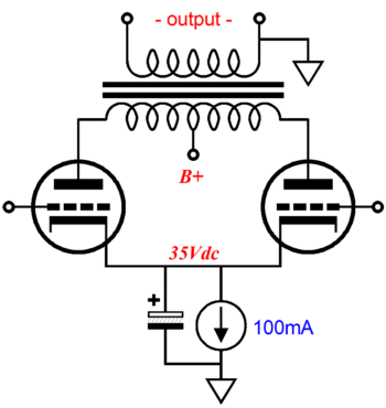
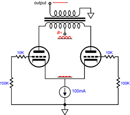
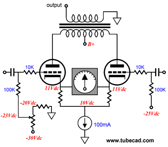
In the above illustration, we see the push-pull output stage with no input signal, but with a good amount of power-supply noise. Since the constant-current source strives to maintain a fixed current flow throughout the set of power tubes, it cannot let the variations in B+ voltage (power-supply noise) vary the tube's current conduction, so the cathode voltage must move 1/(mu + 1) as much as the B+ moves. The result is noise-free output at the speaker, in spite of the plates and cathodes bouncing about. Remember, if there is no delta, no difference in current flow through the primary, then there cannot be any output signal at the secondary. CMRR is less well known. It stands for common-mode-rejection ratio and it is the measure of an amplifier's ability to reject in-phase input signals relative to its amplification of uncommon input signals, i.e. balanced input signals. Ideally, an amplifier would entirely ignore an identical signal at its positive and negative (non-inverting and inverting) inputs. Wait a second; why should there be any in-phase input signals with a push-pull, balanced pair of out-of-phase input signals? There shouldn't be...but there always are. That's real life. Sometimes the culprit is RFI or magnetically coupled hum or just a less-than-perfect power supply feeding the phase splitter or the differential long-tailed amplifier that delivers its output to the output stage. With the unbypassed constant-current source in place, the cathode follows the common-mode signal, which prevents the tubes from seeing an input signal; and, probably much more importantly, prevents the common-mode signal from interacting with the desired input signal within the output tubes.
In other words, greatly enhanced PSRR and CMRR are wonderful attributes to have—in the real world of electronics. In a perfect world, one free of all RFI and filled with perfect house wiring and noiseless, absolutely fixed power supplies and flawless input signal sources, these two highly-desired characteristics would not be necessary. In fact, if the power supplies were perfectly clean and steady, and if the triodes were perfectly linear, then it would make no real difference if the constant-current source were unbypassed or bypassed or, indeed, if it were replaced with battery or a perfect zener diode. What? Once again, as long as the amplifier were never driven beyond its class-A envelope of operation and as long as perfect power supplies and tube were used, the connected cathodes would never budge a picovolt, which means that the tubes would be entirely indifferent to what load was found between them and ground. But as we do live in a less-than-perfect world, we have to prepare for the worst. We can design better power supplies and buy more closely-matched output tubes—and we do not bypass the constant-current source.
By the way, each output tube could see its own connection to a negative bias voltage, so that the constant-current source would displace less precious voltage and so each output tube could have its idle adjusted independently from its partner. Or we could use a DC servo loop to automatically adjust one tube's grid voltage so that the tube matches its partner's conduction. The most difficult correction to make, however, is changing ourselves. Audiophiles like to crank the volume. With a huge increase in sound pressure comes a feeling of power and an uncovering of sonic details. Unfortunately, super loud and class-A are seldom seen together. Unless you are running big 105dB horns, you are probably clipping at least once during every minute of music play. It is easy to do, as quality music presents a huge dynamic range, which would require 10kW amplifiers to reproduce faithfully with typical inefficient speakers. But when we bought class-A glory we had to pay in potential wattage (and in heat and shorter tube longevity). For example, the two output tubes that could have produced 100W in a super-lean class-AB, might only produce 25W in strict class-A.
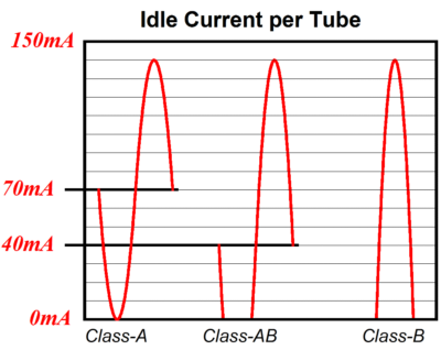
The above graph shows three idle current points and the three resulting classes of operation. In all three examples, the peak current draw by a single tube is 140mA. But the class-A idle current limits the amplifier's output to one half of what the class-AB point yields and only one forth what the class-B idle current can deliver. Moreover, the tube will last much longer with the lower idle currents. Of course, the lowest distortion and the flattest output impedance will be offered by the class-A mode of operation. I believe this is a good trade; but never forget that some tradeoff must always be made.
TCJ Workaround
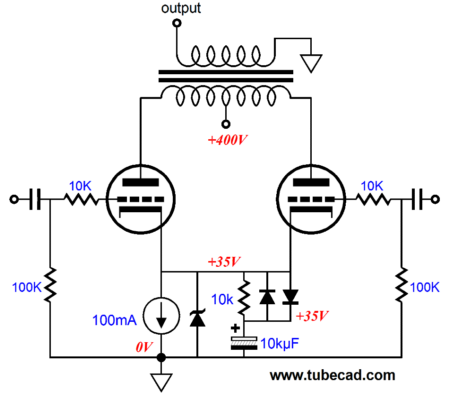
To begin with, just imagine the zener is not there, which would leave just the constant-current source and two diodes, a resistor, and a large-valued capacitor. Note how the capacitor is at the same voltage as the cathodes, which makes sense as the 10k resistor and the rightmost diode will charge up the capacitor. Once charged, the capacitor only sees the 10k resistor connecting it to the cathodes, as the two diodes are no longer forward biased, so they effectively fall out of the circuit. Now, if we never increase the volume beyond the class-A limit, the constant-current source is only being shunted by a 10k resistor, which can be safely ignored. On the other hand, if the crescendo takes an output tube outside the class-A envelope, the rightmost diode will begin conducting and effectively couple the capacitor to the cathodes, which will greatly limit their AC movement away from the established DC bias voltage. Of course, if the increased volume is sustained for long enough, the capacitor will charge up to a much higher voltage. But once the volume falls to normal, the leftmost diode will begin conducting, allowing the capacitor to discharge through the constant-current source. It's not perfect, but it would allow a two-speed operation to the amplifier. In other words, instead of having a class-A amplifier that puts out only 25W, we could have class-A amplifier that puts out nominally only 25W, but could be overdriven to produce clean 50W (or more) bursts of power. Okay, why is the zener there? The zener diode will put the hard breaks on the cathodes climbing too high in voltage due to rectification effects that result from overdriving the triodes. Just pick a zener that will break at some voltage beyond what you ever expect to find a triode biasing to at the desired idle current. In fact, we could just use a zener and the constant-current source, but it results in sharp transitions in the waveform—never a sonically good idea. The more complex circuit allows a smoother transition.
I have run many SPICE simulations on the above circuit and it performs well. I would use MUR410G rectifiers and LM317-HV three-pin, TO-220 voltage regulators to create the constant-current source. If an EL84 were used, then a plain LM317 could be used; if 300Bs are used, then the TL783 is a better choice. See www.tubecad.com/february2000/page6.html for more information. Of course the assumption throughout has been that carefully matched tubes would be used. Great. But what if we don't own matched tubes or what if our once matched tubes fall out of matching over time? The following workaround illustrates how two unmatched output tubes could be used.
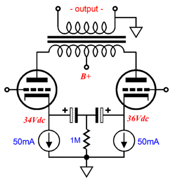
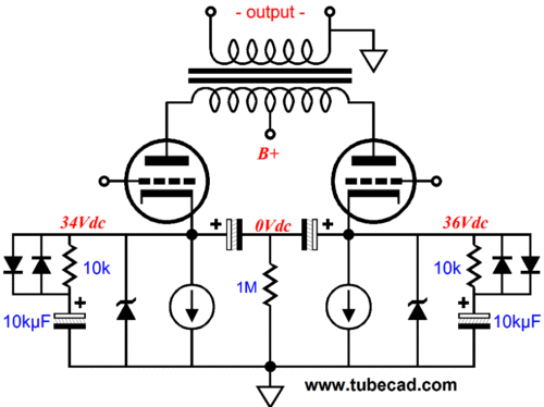
The two large capacitors effectively couple the two cathodes in AC terms, but allow each tube to find its own DC bias voltage. The 1M resistor establishes a polarizing voltage across each capacitor. Why? I think electrolytics sound better when they hold a charge. Of course, we do not have to stop at two output tubes, as we could run eight tubes, with each tube getting its own constant-current source and big capacitor. And, yes, the same fancy additions of zener, resistor, big capacitor, and two diodes can be added, but one set per tube.
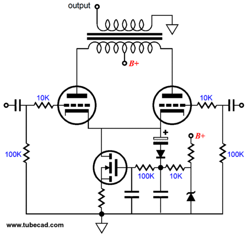
Okay, one final idea (I could easily go on for twice as long). How about a push-pull amplifier with an auto-bias constant-current source that is set to a nominally low value, so the amplifier only puts out 4W in class-A—until a crescendo forces the constant-current source to climb to a higher level of current conduction; then when the music subsides, the constant-current source falls back to previous value.
In this example, a MOSFET was used, but the three-pin regulators could still be used, but with some slight adjustments to the topology. The downside to this approach is that the sliding bias reacts to changes in current demand, not anticipates the changes before they happen. The ideal would be a computer-based sound system, wherein the idle current through the constant-current source could be dynamicaly adjusted by the computer. Such a setup would give us just about everything we desire: long tube life, low heat, high power, and class-A glory on the cheap. See blog number 126 for more information.
Next Time
//JRB |
I know that some readers wish to avoid Patreon, so here is a PayPal button instead. Thanks.
John Broskie
And
High-quality, double-sided, extra thick, 2-oz traces, plated-through holes, dual sets of resistor pads and pads for two coupling capacitors. Stereo and mono, octal and 9-pin printed circuit boards available.
Designed by John Broskie & Made in USA Aikido PCBs for as little as $24 http://glass-ware.stores.yahoo.net/
The Tube CAD Journal's first companion program, TCJ Filter Design lets you design a filter or crossover (passive, OpAmp or tube) without having to check out thick textbooks from the library and without having to breakout the scientific calculator. This program's goal is to provide a quick and easy display not only of the frequency response, but also of the resistor and capacitor values for a passive and active filters and crossovers. TCJ Filter Design is easy to use, but not lightweight, holding over 60 different filter topologies and up to four filter alignments: While the program’s main concern is active filters, solid-state and tube, it also does passive filters. In fact, it can be used to calculate passive crossovers for use with speakers by entering 8 ohms as the terminating resistance. Click on the image below to see the full screen capture.
Tube crossovers are a major part of this program; both buffered and un-buffered tube based filters along with mono-polar and bipolar power supply topologies are covered. Available on a CD-ROM and a downloadable version (4 Megabytes). Download or CD ROM
|
|||


| www.tubecad.com Copyright © 1999-2011 GlassWare All Rights Reserved |