| John Broskie's Guide to Tube Circuit Analysis & Design |
09 December 2006
More on Class-XD™
My last entry sputtered to an end without my ever mentioning the star of this website—the triode. Don't worry; I will put the “tube” back into the Tube CAD Journal soon enough. Even when no tubes are in sight, tube circuits are always at least implicit in the Tube CAD Journal. How's that? In general, a sharp divide separates solid-state from vacuum-state electronics, but only on a physical level. Topologically, the division is much more rounded and shallower, if not totally nonexistent. Indeed, the only sharp, unbridgeable divide is the P-channel versions of the MOSFET and FET, and the PNP version of the transistor that finds no equivalent in the vacuum tube world. In other words, just about any technique/topology can be translated from one device technology to another. For example, I have performed the electronic-alchemist’s trick of converting glass into silicon and solid-state into vacuum-state many times in this journal: the tube-based White cathode follower, SRPP, Broskie cathode follower, and Aikido amplifier into solid-state circuits; the solid-state-based Taylor and the Macaulay amplifiers into tube-based amplifiers. Here is an incomplete list:
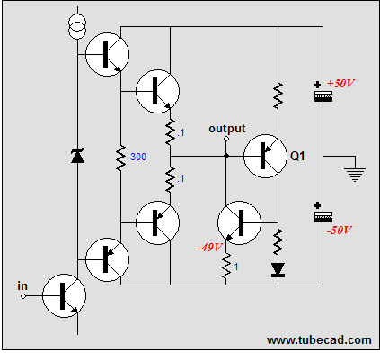
Last time, I had a good time teasing Audio Advisor and Cambridge Audio; the former by deflating its sales copy’s egregious exaggeration and the latter by refuting its claim to originality. But don't get me wrong, I don't claim to have invented crossover-notch shifting. In fact, the technique of forcing a push-pull amplifier into single ended operation over a small portion of its output, so that its crossover notch is shifted away from the zero crossing, is at least 20 to 30 years old. Just about anyone who has seriously worked with OpAmp ICs knows about the technique of adding a pull-down resistor or constant-current source to an OpAmp’s output to force the internal output stage to undergo a crossover-notch shift. My only claim to originality in my 2002 essay on Mixed-mode Amplifiers was pointing out that the crossover-notch-shifting constant-current source could be housed externally to the amplifier to which it is attached, with its own external power supply and enclosure, something of a possible high-end audio accessory that would bestow a single-ended glory on existing push-pull, solid-state amplifiers. Well, I am grateful to Tube CAD Journal reader James in Australia, who sent the link to the Cambridge Audio’s British patent. In the patent, we read:
I guess this means that all those OpAmp-based circuits built for the last thirty years that used pull-down resistor and constant-current source on the output will have to be desoldered and anyone who built an amplifier based on my 2002 essay or the headphone amplifier based on my 2001 schematic will have to revert their amplifiers back to conventional push-pull mode and live with the crossover-notch distortion at the zero-crossing, as this patent owns it all. Or does it? Let's be frank, everyone except patent holders and the patent office will admit that the patent system is broken. Crazy, silly, obvious, and prior-art existing ideas receive patents every day. Remember the madness of granting Amazon.com the patent for one-click purchasing? Well, I should have patented two-click purchasing, and you should have patented three-click purchasing, and someone else four-click purchasing… then every time an online purchase is made it will take eight clicks. Eight clicks? Don’t I mean 4,132,482 clicks? No, as the patent office usually takes a year of careful deliberation before granting each patent—which behooves such subtle, complex, and clever inventions—it will be quite sometime before we get to 4,132,482 clicks. Here is a suggestion: all patent applications should cost $2,000; and all applications are immediately approved; then if someone can show that the invention has already been patented or is obvious or doesn’t work as promised or finds prior art, then that worthy individual (or company or institution) is awarded $1,000 as a reward from the patent office and the patent is thrown in the trash. If two years pass with no dethroning, a long-term patent number is assigned.
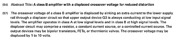
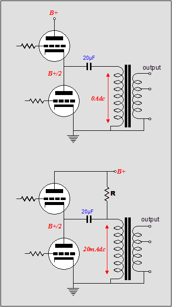
This topology loads one output tube with a constant-current source, while the other output tube is cut off. If a resistor were used in place of the third pentode, the current draw through the resistor would be in the same current phase (but the opposite voltage phase) as the active output tube. This is not the way to go, in terms of efficiency, although I am not convinced that it doesn’t have some merit in terms of distortion. But how do we achieve the inversion of the resistor’s current draw, as in the Cambridge Audio amplifier? Below is one possibility.
Or, instead of driving the screen, we drive the grid, which would allow triodes to be used instead of pentodes.
Transformer crossover-notch distortion
For example, we could build an OTL amplifier of sorts to which we then attach an output transformer (air-gapped) via a large-valued coupling capacitor. Then we listen and measure, but not at full output, but rather at 1W of output. Next we add a resistor that bridges the secondary to the B+ voltage. Now the secondary will experience a DC bias current, which will shift the hysteresis-induced crossover-notch away from the zero–crossing point. My bet is that the resistor-laden version wins. Next time //JRB
|
Only $12.95
Download or CD ROM www.glass-ware.com
High-quality, double-sided, extra thick, 2-oz traces, plated-through holes, dual sets of resistor pads and pads for two coupling capacitors. Stereo and mono, octal and 9-pin printed circuit boards available.  Aikido PCBs for as little as $24 http://glass-ware.stores.yahoo.net/
The TCJ Stepped Attenuator The center knob controls both channels, and offers six large decrements; the flanking knobs offer six fine decrements for each channel, creating a volume control and balance control in one easy-to-use stepped attenuator. This clever attenuator uses fewer resistors (only 32) than would be expected from a conventional 32-position stepped attenuator, as two series attenuators would need a total of 72 resistors; and two ladder attenuators would require 140 resistors. In addition, the PCB holds dual sets of resistor pads, one wide and one narrow, so that axial (composition, wire-wound, and film) and radial (thick-film and bulk-foil) resistors can be used without extra lead bending. Although designed to go with the Aikido amplifier, it can be used anywhere a high-quality attenuator is needed, whether passive or active. For example, it would make a first-rate foundation to an excellent passive line box. Visit our Yahoo Store for more details: http://glass-ware.stores.yahoo.net/
The Tube CAD Journal's first companion program, TCJ Filter Design lets you design a filter or crossover (passive, solid-state or tube) without having to check out thick textbooks from the library and without having to breakout the scientific calculator. This program's goal is to provide a quick and easy display not only of the frequency response, but also of the resistor and capacitor values for a passive and active filters and crossovers. TCJ Filter Design is easy to use, but not lightweight, holding over 60 different filter topologies and up to four filter alignments: While the program’s main concern is active filters, solid-state and tube, it also does passive filters. In fact, it can be used to calculate passive crossovers for use with speakers by entering 8 ohms as the terminating resistance. Click on the image below to see the full screen capture.
Tube crossovers are a major part of this program; both buffered and un-buffered tube based filters along with mono-polar and bipolar power supply topologies are covered. Available on a CD-ROM and a downloadable version (4 Megabytes). Download or CD ROM
|
|||
.png)


| www.tubecad.com Copyright © 1999-2006 GlassWare All Rights Reserved |