| John Broskie's Guide to Tube Circuit Analysis & Design |
29 April 2024 Post Number 601
Super-Triode Input Stages
Yes, we can dream and some dreams do come true. From post 375 we learn:
(By the way, Google led me to post 375, which I had largely forgotten. Mercy. I was tickled mightily by it, as I found its tongue-in-cheek insouciance both humorous and impudent by modern-cultural standards. Definitely a contender for entry into a future anthology, "The Best of Tube CAD Journal".) From this post we see these two graphics:
This is the super-triode's grounded-cathode-amplifier configuration. (We can also make super-triode cathode follower, grounded-grid amplifier, and split-load phase splitter versions.) The inverting solid-state amplifier can take many forms; it can be an OpAmp or discrete circuit that holds many transistors or just a single transistor (or a vacuum tube or MOSFET). If the super-triode grounded-cathode amplifier is correctly setup, the signal gain realized equals the amplification factor (mu) of the triode; thus, a 6SN7 would yield a gain of 1:20 or +26dB. If the super-triode hybrid amplifier fails to deliver the full mu of the triode as gain, then the triode is not actually being run in the constant-current source mode. In other words, the triode's cathode or plate is being dragged down in some fashion. To avoid this pitfall, the inverting solid-state amplifier must exhibit high open-loop gain. In fact, we can view the triode as acting as the solid-state amplifier's negative feedback loop. In the circuit on the right, we can replace the plate resistor and capacitor with a transistor.
This arrangement allows us to lower the bottom transistor's idle current and raise the collector resistor's value, thereby increasing the gain from the bottom transistor. Additionally, we can exchange the top transistor with another triode.
As shown, the two triodes are most probably identical, since they share the same glass envelope, but they could differ. One potential problem we face is that the NPN transistor's emitter-to-base voltage is a mere 0.6V to 0.7V, whereas cathode voltages in most audio circuits are higher. One workaround is to add as many diodes as needed to bring the base voltage up to the cathode's.
The 2.2µF capacitor and the two collector resistors work to vastly improve the PSRR of the circuit, without loss of any gain. In fact, this setup might yield a closer approximation to the triode's mu, as the bootstrap capacitor effectively multiplies the 82k resistor's resistance by many times, making it closer to being a constant-current source. Having mentioned constant-current sources, we can forgo the addition of the capacitor by using a constant-current source in place of a collector resistor. Moreover, we can replace the NPN transistor with another triode.
Note that the super-triode cathode resistor has been exchanged for a constant-current source. In SPICE simulations, this swap did not yield enhanced performance with a bottom NPN transistor, but as a triode exhibits far, far lower transconductance than a bipolar transistor, the constant-current source is probably a good idea. A key feature of all these super-triode arrangements is that the bottom triode draws a near constant current, while the top transistor or triode or MOSFET undergoes the current-flow variations. In other words, as far as the output signal is concerned, this is a single-ended output stage. The triode's constant-current conduction allows us to augment the triode's constant-current flow with an in-parallel additional constant-current source.
Here we see a single-ended headphone amplifier that can drive 32-ohm headphones. Note that the triode only draws 3.3mA, while the MOSFET draws 153.3mA at idle. The 150mA constant-current source will get hot, as it must dissipate 9W. Since the constant-current source's current equals that of the 12AU7's heater element. Each channel gets half of the heater's resistance, which is easy to do, as pin 9 center-taps the heater element.
The MOSFET, in contrast, the MOSFET only dissipates 3W. In my SPICE simulations of this circuit, I used an IRF520, which is a 100V, 60W N-channel MOSFET in the TO-220 package. With a constant-current source current conduction of 150mA, we can expect up to 4.8Vpk of output voltage swing with 32-ohm loads. With 4Vpk of output at 1kHz, we get the following SPICE-generated Fourier graph.
It took 1Vpk of input signal to deliver the 4Vpk of output signal into 32-ohms. The THD is plenty low with a nice single-ended 2nd harmonic enrichment and fine attenuation of the 3rd harmonic. Okay, we have concluded our super-triode warmup exercises and can proceed to making a hybrid power amplifier that exploits the super-triode topology. Since few chip amplifiers can operate low gains, let alone unity-gain, the tube-based frontend doesn't need to deliver much gain at all—just enough to drive the inverting solid-state power amplifier to full output.
Note the relatively low B+ voltage of 120Vdc for the tube stage. Also note the relatively high input resistor value of 47k; this will be (roughly) the power amplifier's input impedance. The super-triode frontend delivers a gain only 1:1.5 or 3.5dB. If more gain is needed, we can replace the 75k resistor with one of a higher value, say 100k to 150k. If unity-gain is our goal, we would use 51k. The output impedance is crazy low, as in below one ohm! Yes, in spite of the tubes, the output impedance is less than one ohm, the result of the transistor's high gain and the negative feedback loop. The PSRR is greater than -70dB. Here is an example of how we can get three power-supply voltages from a single center-tapped secondary. Instead of 50Vct, we would use a 56Vct secondary to get ±40Vdc along with +120Vdc.
The PSRR is excellent.
The THD is vanishingly low, as the following graph reveals.
Note the lovely extra suppression of the 3rd harmonic. One item I left out of the circuit, however, was an input coupling capacitor, which made me a wee bit nervous, as we do not want any amplification of a DC offset voltage riding on the input signal. My reasoning was that even if a 6mV DC voltage appeared at the input, only 1mVdc would leave the solid-state amplifier, as the DC gain is only 1:0.163; in other words, the DC gain is less than unity-gain by a six-fold attenuation. On the other hand, we could add an input coupling capacitor to produce a 1st-order high-pass filter function. Why? Let's say you wish to use subwoofers below 100Hz, and you want to cut off the low-frequency bandwidth at 100Hz with a gentle -6dB-per-octave slope for the main loudspeakers. (By the way, the high-frequency bandwidth extends out to 1.5MHz for the super-triode portion of the circuit.)
The actual input impedance is closer to 48k than 47k, so the 33nF (0.033µF) input coupling capacitor works to create the 100Hz transition frequency. Speaking of capacitors, the 10µF capacitor is enclosed within the super-triode's negative feedback loop, so its value is effectively magnified, which means that we could get away with using a smaller capacitor value, say just 1µF, and still get low-frequency bandwidth to below 20Hz. I don't, however, recommend it. Why not? The distortion will rise, which was confirmed in SPICE simulations. Part of the increase was due to a failing of Fourier analysis in SPICE, as it is sensitive to phase shift, something that an actual distortion analyzer would ignore. But the big problem is that we are squandering negative feedback to artificially enlarge the capacitor's capacitance rather than just lower distortion and output impedance. An analogy is having money in the bank—say enough to buy a yacht or a nice condo or a vintage Ferrari—but not enough to buy all three. Negative feedback can lower distortion or output impedance or increase bandwidth, but asking it to do all three at once when we can bypass the need to extend bandwidth is foolish. One possible exception might be that your favorite fancy coupling capacitor cost $150 in the 1µF value, but close to $1,000 for the 10µF version. Bear in mind that since the coupling capacitor falls within the negative feedback loop, its distortion (oops, its unique sonic attributes) will be reduced by the negative feedback.
My recent purchase of Sennheiser HD 660S2 headphones came with an array of cables that included balanced cables which terminated in the Sony 4.4mm Pentaconn balanced plug. This got me thinking about balanced drive for headphones again—but along different lines, as my last post made the argument in favor of single-ended balanced output, not push-pull.
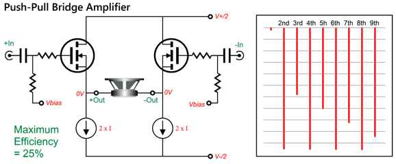
If we use two triodes or two N-channel MOSFETs or two NPN transistors loaded by two constant-current sources, we get push-pull output, as the active devices conduct current in anti-phase, resulting in the jagged harmonic structure that notches out even-order harmonics, but leaving odd-order harmonics in place.
On the other hand, if we use both an N-channel and P-channel MOSFET with the two constant-current sources, we end up getting single-ended harmonic signature, as the two MOSFETs run in current phase.
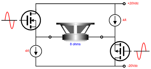
The MOSFETs see anti-phase input voltage signals, but their current conduction is in phase, i.e. as one conducts more so, too, does the other. Let's compare this to the push-pull arrangement that uses two N-channel MOSFETs.
The MOSFETs still see anti-phase input signals, but their current conduction is in anti-phase, for as one conducts more the other conducts less. By the way, the two output coupling capacitor might seem excessively large in value, but they aren't. Effectively the two coupling capacitor are in series, so their capacitance halves, leaving 310µF of capacitance. With 32-ohm headphones, the low-frequency cutoff frequency will be equal to 159155/310/32 or 16Hz. If you only plan on driving 300-ohm headphones, then 62µF coupling capacitor could be used. The 200mA constant-current sources might also appear excessive, but the higher current flow results in more linear output from the IRF520 MOSFETs. The constant-current sources can easily be made from LM317 voltage regulators by using 6.2-ohm adjustment resistors in series with output and ground. The 200mA constant-current sources impose maximum output voltage swing of 6.2Vpk with 32-ohm headphones. With 300-ohm headphones, we can expect something closer to 8Vpk of output. Each channel will dissipate 4.8W at idle, so each active device will dissipate 1.2W, which is so trivial that the smallest heatsink can be used. Now, let's turn to the single-ended alternative arrangement, wherein N-channel and P-channel MOSFETs are used.
For many readers, their eyes will see a push-pull output stage; nonetheless, the output stage is single-ended. Balanced output does not necessarily imply push-pull. Phono cartridge coils and microphones can count as balanced signal sources, but no pushing and pulling occurs; or put more clearly: only one current phase exists. Current phase is the true measure of single-ended and push-pull operation. Thus, ignore appearance and focus in on the current conduction. Once again, 200mA constant-current sources load the MOSFETs and the output coupling capacitors present 620µF of capacitance. The power supply can be either switch-mode wallwart of a conventional power supply filled with rectifiers and capacitors, possibly regulated. Many, if not most, high-end DACs offer balanced output along with RCA jacks. These DACs usually can deliver 2Vpk and 4Vpk-to-pk of balanced output, which is plenty for most low-impedance headphones and even 300-ohm Sennheiser headphones. (Your smart phone probably puts out a peak of 1V. Every doubling of output voltage is quadrupling of power. Thus, 4Vpk deliver 16 times more power than 1Vpk.) If more gain is needed, we can add a tube-based input stage.
Very little gain is needed, so the 12AU7 is a good candidate. The two 200-ohm resistors burn off some gain and linearize the 12AU7s. The 10ma constant-current source can be an LM334, in spite of the relatively low cathode voltages. Remember that the balanced input signal means that the constant-current source will see a constant voltage drop. How's that possible? As one triode's cathode swings up in voltage, the other cathode swings down in voltage, with the average equaling the idle voltage.
I ran SPICE simulations on this circuit and was quite pleased with the results, save for the high-frequency bandwidth falling off at 160kHz due the MOSFET's relatively high input capacitance and the differential input stage's relatively high output impedance. I then bypassed the two 200-ohm cathode resistors with each getting a 5.1nF shunting capacitor; the bandwidth then extended to 190kHz. I didn't like the change in harmonic structure, however, so I remove the bypass capacitors. Here is the SPICE-generated Fourier graph for 1Vpk at 1kHz into 32 ohms.
This is an example of single-ended glory. Note the strong 2nd harmonic and the smooth cascade to -120dB. By the way, -60dB translates to 0.1% and -120dB is a thousand times lower still. Now we compare this to the version that uses only N-channel MOSFETs.
To be frank, this is better than I expected, although the high 3rd harmonic content is troublesome. (If the differential input stage held a negative feedback loop to the output stage, the classic push-pull signature would be more evident.) If we increase the output voltage swing to 4Vk, the differences become more extreme. Fist the single-ended arrangement with N-channel and P-channel MOSFETs.
Dang if that doesn't look perfectly single-ended. Next, the all N-channel MOSFET version.
Dang if that doesn't look woefully push-pull. You do not have to guess which headphone amplifier I would prefer to use. I have not done the required math, but my bet is that the push-pull version offers lower THD, but worse sonics. I wondered if the sought-after single-ended harmonic structure would survive high-negative-feedback. For example, what if we used two OpAmps to control the two output devices?
In SPICE simulations, I replaced the N-channel and P-channel MOSFET output stage with the one above. The OpAmp SPICE model was of the ideal OpAmp, which is basically perfect which no real OpAmp is. The tube-based differential input stage provided the needed balanced drive signals. Here is the SPICE-generated Fourier graph:
So far, the buffers have been arrayed horizontally. What if we go vertical? Usually, the translation from horizontal to vertical requires doubling the B+ voltage, but as this is meant to be a headphone amplifier, not a loudspeaker power amplifier, we will only increase the B+ voltage by 150%.
The LM317-based constant-current source in the center draws 200mA, so the total dissipation per channel is 3.6W, with each solid-state device dissipating around 1.2W. Had we doubled the 12V B+ voltage to 24V, we could get closer to the theoretical peak output voltage swing of 6.4V with 32-ohm loads. With the 18Vdc B+ voltage, we can easily get 3Vpk of output voltage swing. (Do not forget that the LM317 must have a few volts of overhead voltage; also do not forget that the 6.2-ohm resistor sees a constant 1.25V voltage drop.) Here is the SPICE-generated Fourier graph for the circuit.
Once again, we see a splendidly single-ended harmonic structure. If we lack a balanced input stage signal, we can build an unbalanced-to-balanced circuit.
This is a long-tail phase splitter that uses a constant-current source rather a shared cathode resistor and negative power-supply rail. As long as the constant-current source presents an extremely high impedance, the balance is quite good. (Bear in mind that theoretical constant-current sources and actual current-regulating ICs differ.) Of course, we can easily alter this circuit to accept a balanced input signal with some simple switching and an added XLR input jack. The gain for this example is 1:8 at each output or 1:16 differentially, which is plenty. On the other hand, we can use a grounded-cathode amplifier and spilt-load phase splitter frontend.
This frontend can only accept an unbalanced input signal. It deliver a differential output signal gain of 1:20, with the grounded-cathode amplifier input stage producing a gain of 1:10, while the split-load output stage effectively yields a gain of 1:2. The unspecified resistor Ram is the Aikido mojo resistor that forces a deep power-supply noise null. This resistor injects B+ voltage noise into the cathode, causing the grounded-cathode amplifier's PSRR to worsen, but also forcing a power-supply noise null at the headphones. In SPICE simulations, the value of 11.5k worked best, but its value depends on the actual output stage used to drive the headphones. The balanced output stage that I used with this frontend in my SPICE simulations was the following:
This compound arrangement of transistors vastly increases the transistor linearity, as the input transistors (2N4401 & 2N4403) control the output transistors (MJE15032 & MJE15033). In other words, lots of negative feedback is employed. The downside to the compound arrangement is that it can get squirrely at high-frequencies; in addition, its sharp turn-off and turn-on characteristics make it unsuitable in class-AB output stages due to intense gm doubling. Since this output stage runs in strict class-A, however, this second problem does not arise. The first problem is fixed by the 10-ohm base resistors and 30pF capacitors which quell high-frequency weirdness. Another potential problem is that the transistors present a relatively low input impedance, unlike tubes, FETs, and MOSFETs, which forced the use of larger-valued coupling capacitors, 1µF rather than 0.1µF capacitors. I used the previous tube-based frontend with this balanced buffer output stage in my SPICE simulations. Here is the resulting Fourier graph with 2Vpk at 1kHz into 32 ohms.
I like the strong 2nd harmonic and love the majorly attenuated 3rd, but I am not crazy about the remaining harmonics only being down by -90dB. Of course, the only truly important test is reality. I would love to build both vertical single-ended buffers and hold a sonic shootout. Actually, a better shootout would require four variations:
Number three looks promising to me, as the differential input stage comprises a push-pull functioning. I decided to model it in SPICE, but using OpAmps-driving-transistors horizontal version.
I used the "ideal OpAmp" SPICE model for the OpAmps. With 4Vpk of output, we get the following graph.
Sure looks single-ended to me, which no doubt mostly due to the split-load phase splitter. Imagine upping the constant-current source's current draw and using beefy output transistors, as then loudspeakers could be driven. In such a power amplifier, I would use a 6DJ8 in place of the 12AU7. Before leaving this topic behind, I must mention that post 511 hold some super interesting single-ended balanced headphone amplifier designs, such as the following:
Many more interesting circuit are found in that post.
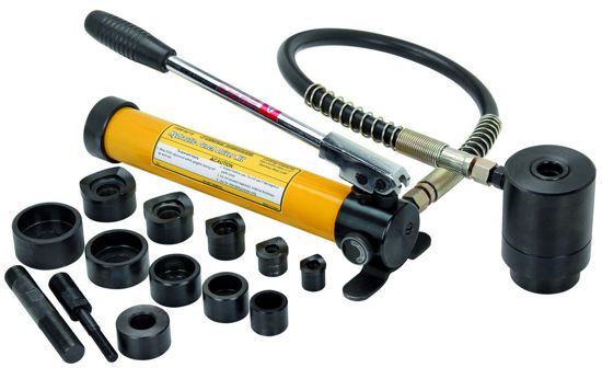
Hole Punches
The hole punch sizes are 0.5, 0.75, 1.0, 1.25 inches in diameter.
I have mentioned Mickey Hart before, but I believe this is the first time one of his albums has been featured. Planet Drum was a big hit when released (1991) and won the Grammy for World Music. Hart brought together drummers and other world musicians from around the world, and some of the tracks feature the Brazilian jazz singer, Flora Purim. I remember reading only one, just one, negative review—a review that bemoaned the album's failure to include a political message or social commentary. Well, one man's failing is another man's blessing. The 25th Anniversary edition was remastered and expanded to include extra tracks in 2016. I have been using one track, "Temple Caves," to test subwoofer output and integration. This track holds some dang deep bass. Well, as so often happens with me, testing mutates into listening. My hunt for other suitable tracks for testing ended with me just listening to the entire album. An hour well spent. Both Amazon Music and Qobuz offer the album in 24-bit, 96kHz format.
//JRB
Did you enjoy my post? Do you want to see me make it to post 1,000? If so, think about supporting me at Patreon.
User Guides for GlassWare Software
For those of you who still have old computers running Windows XP (32-bit) or any other Windows 32-bit OS, I have setup the download availability of my old old standards: Tube CAD, SE Amp CAD, and Audio Gadgets. The downloads are at the GlassWare-Yahoo store and the price is only $9.95 for each program. http://glass-ware.stores.yahoo.net/adsoffromgla.html So many have asked that I had to do it. WARNING: THESE THREE PROGRAMS WILL NOT RUN UNDER VISTA 64-Bit or WINDOWS 7, 8, and 10 if the OS is not 32-bit or if it is a 64-bit OS. I do plan on remaking all of these programs into 64-bit versions, but it will be a huge ordeal, as programming requires vast chunks of noise-free time, something very rare with children running about. Ideally, I would love to come out with versions that run on iPads and Android-OS tablets.
|
I know that some readers wish to avoid Patreon, so here is a PayPal button instead. Thanks.
John Broskie
John Gives
Special Thanks to the Special 86 To all my patrons, all 86 of them, thank you all again. I want to especially thank
I am truly stunned and appreciative of their support. In addition I want to thank the following patrons:
All of your support makes a big difference. I would love to arrive at the point where creating my posts was my top priority of the day, not something that I have to steal time from other obligations to do. The more support I get, the higher up these posts move up in deserving attention.
If you have been reading my posts, you know that my lifetime goal is reaching post number one thousand. I have 399 more to go. My second goal was to gather 1,000 patrons. Well, that no longer seems possible to me, so I will shoot for a mighty 100 instead. Thus, I have just 14 paying patrons to go. Help me get there. Thanks.
Only $9.95
The Tube CAD Journal's first companion program, TCJ Filter Design lets you design a filter or crossover (passive, OpAmp or tube) without having to check out thick textbooks from the library and without having to breakout the scientific calculator. This program's goal is to provide a quick and easy display not only of the frequency response, but also of the resistor and capacitor values for a passive and active filters and crossovers. TCJ Filter Design is easy to use, but not lightweight, holding over 60 different filter topologies and up to four filter alignments: While the program's main concern is active filters, solid-state and tube, it also does passive filters. In fact, it can be used to calculate passive crossovers for use with speakers by entering 8 ohms as the terminating resistance. Click on the image below to see the full screen capture.
Tube crossovers are a major part of this program; both buffered and un-buffered tube based filters along with mono-polar and bipolar power supply topologies are covered. Available on a CD-ROM and a downloadable version (4 Megabytes). Download or CD ROM
|
|||


%20Cover.jpg)


| www.tubecad.com Copyright © 1999-2024 GlassWare All Rights Reserved |