| ||
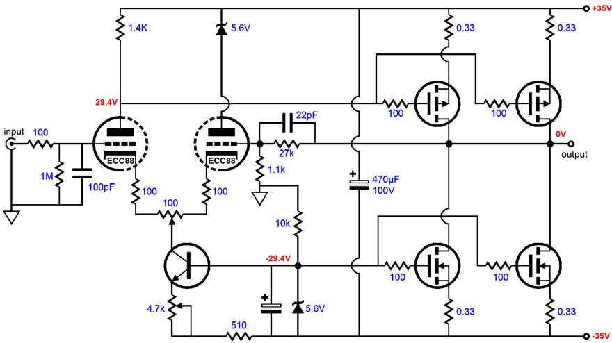
| Thus, the first change I would make would be to eliminate the current mirror and replace with a single plate resistor and a zener diode, as shown above. Strictly speaking, the tube portion of the amplifier is no longer a differential amplifier but instead a common cathode amplifier, as the second triode's plate voltage is locked, while the first triode's plate experiences all the voltage swings. Direct coupling is used and the MOSFET probably only needs 1 volt of swing to work, which is adequately covered by even this small value for the plate resistor. In fact, the low gain the first triode yields works to keep the input capacitance low.
The punch line is that transistors have found their preferred practices, methods, implementations, and topologies; so to it is with MOSFETs and vacuum tubes. The original front-end would probably be happier with a transistor output stage, as the transistor's base will load and thus reference the output of the differential amplifier; and this remake I am recommending would probably work better with a MOSFET output stage, as the output is referenced to the top power supply rail and it will not be resistively loaded down by the MOSFET's gate. If you are uncomfortable with the idea of retrogressing in design fashion, try at least an experiment: keep the present current mirror, but short the common bases to positive rail with a large valued capacitor. |
This move will tend to revert the input stage to a single-ended state in AC terms. No matter what you decide, please send us your results. Before moving on to your second question, let's take an other overview of the unmodified amplifier. One problem spot is power supply filtering. Starting with the bottom MOSFET, this device is used as a current source which finds its voltage reference in the zener diode. The hope is that the MOSFET's gate sees a constant voltage that tracks the negative power supply rail's noise; for if it doesn't, that noise will appear as a signal to be amplified. Placing the 5.1 volt zener on the other side of the filter ruins that tracking. Remember the whole point of the filter is to decouple. The solution is simple: just short out the 100 ohm resistor (and increase the value of the zener to compensate for the loss of voltage drop). Now the MOSFET's source and gate synchronize. Does the filtering at the top of the amplifier also cause problems? It will, if the conversion to a simple plate resistor load is made, as the top MOSFET should also see the same power supply noise superimposed on its gate as it sees on its source. Shorting out the top 100 ohm resistor is, once again, the answer. |
|
| www.tubecad.com Copyright © 2001 GlassWare All Rights Reserved |