| I imagine that the rejoinder goes something like this: "What's math got to do with it? Just look at it; it's the same size as a ST-70 output transformer; therefore, it must put out the same wattage." Or how about the latest inanity from the ad department on steroids: "Our push-pull amplifier is not a push-pull amplifier after all, but rather two single-ended amplifiers working into the same load." Push-pull operation means anti-phase current conduction of the output devices and this amplifier's output tubes do just that. Oh, if only enough horsewhips could be found.
Still, if the amplifier sounds good who cares if the specifications are somewhat bloated? But apparently this amplifier doesn't sound as good as you would like. Where to start? I don't imagine that the current mirror, as implemented, does much good in this hybrid amplifier. Remember all those silly circuits that were designed when transistors first appeared on scene. The assumption was that the transistor should be forced into preexisting tube circuit topologies. What could the transistor be but some variation on the tube? Or at least that what many thought at the time. Something along similar lines is going on here. Do not get me wrong; I believe that the cross-fertilization between electronic technologies has great practical importance and offers some excellent amusements. When done correctly that is. So is the answer to be found in using a tube current mirror instead? This begs the next question first: Can a current mirror even be made out of tubes?
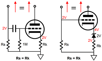
Yes, it can, but I doubt that you will find it of much use. The circuit is simple enough: one triode and a few resistors and a coupling capacitor. Current variations through resistor Rs, the sense resistor, become AC voltage variations, which are relayed to the triode's grid via the coupling capacitor. Then the cathode applies this same AC voltage variation to the cathode resistor Rk, which in turn realizes an AC variation in current to match that through resistor Rs. As the cathode follower experiences some gain loss, the same valued resistors should not be used. Instead, the cathode resistor should equal the cathode follower's gain against the value of resistor Rs. This circuit only mirrors AC current variations, but it can be converted to DC mirroring by adding a zener diode whose voltage matches the grid-to-cathode voltage. Since tubes only come in N-channel flavor, this current mirror cannot be used in place of a PNP transistor based current mirror. |
In other words, the tube based current mirror will not work in this circuit unless the differential amplifier is inverted and uses PNP transistors, as the this change would allow DC coupling to the tube current mirror. Still, I do not think it would be worth the effort.
Ask your self: Why is the current mirror used in most transistor amplifiers? This circuit solves at least two problems. The first is that the differential pair are seldom that well matched. The current mirror (current matcher) feebly helps the two to track each other, which slightly helps improve DC relationships within the amplifier. This will work much better with triodes, as triode exhibit a low plate resistance. Do not forget that we can control the current flow through a triode in three ways: we can alter the grid voltage or the cathode voltage or the plate voltage, with the cathode being mu + 1 times more effective that the plate, the grid being mu times more effective, and the plate being 1/mu times as effective as the grid. In other words, the current mirror helps keeps the DC offset inline and reduces the distortion from the differential pair by keeping the pair centered. The second problem is that using a resistor load in placeof the current mirror just limits the potential gain and the symmetry of the slewing. In the example of the hybrid power amplifier, the current mirror loads the left triode with a near infinite impedance that boasts its gain, while providing a means of pulling up as hard as the triode below can pull down. Yes, for those readers that have just had a flash of recognition, the current mirror completes the second half of a push-pull amplifier. As the left riode increases it cureent conduction, the right triode decreases its, but the transistor above it wants to increase its conduction, as it mirrors the conduction of the trnasistor at its left. The result is push-pull operation, as the two electronic device are runing in AC current antiphase. This amplifier is still a pure Class-A affair, but push-pull nonetheless. And the great advantage to a Class-A push-pull amplifier is that it can deliver twice the idle current into a load that a single-ended class-A amplifier would witht he same idle current. In this example, the load is the gate of the following MOSFET (and the MOSFET's input capacitance and/or whatever compensation capacitance is used). The question is: Do you really want a push-pull amplifier that does a fine job of eliminating 2nd harmonic distortion while retaining odd order ones to drive your single-ended output stage? In other words, is the current mirror really required? The single MOSFET does not have that linear of a transfer curve, so why bend over backwards to give it a linear input signal? Why not try to feed it a complementary non-linear input signal instead? Eliminating distortion by providing a complementary pre-distortion is effective, although often difficult to achieve. | |
| www.tubecad.com Copyright © 2001 GlassWare All Rights Reserved |