| John Broskie's Guide to Tube Circuit Analysis & Design |
| July 14 2026 | Post Number 643 |
||||
Oxford English Dictionary
Headphones for Radicals
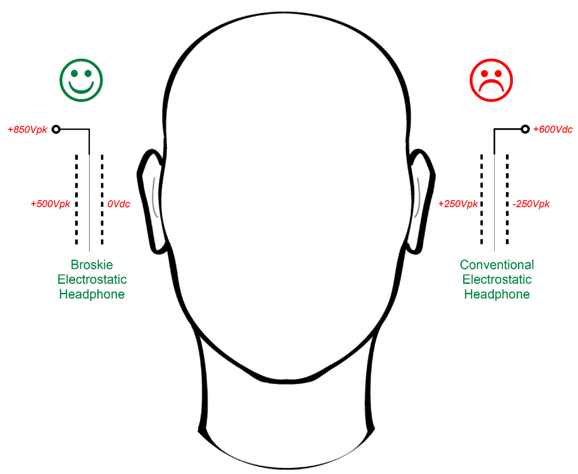
Another worrying thought: our head placed between two high-voltage plates of metal, our ears just millimeters away from boisterous AC voltages, voltages that swing into the hundreds of volts. Sure, that's what I want to do. No thanks. Yet, that is what I do each time I place my Stax electrostatic headphones upon my head—and I am not alone. My alternative electrostatic headphone grounds the stators (a perforated thin sheet of metal that sound travels through) nearest the ear, while energetically driving the diaphragms and opposing stators.
As far as the diaphragm is concerned, both arrangements are identical, in terms of the voltage relationships between the diaphragm and its stators, 850V and 350V. At idle, i.e. no music, both electrostatic headphone designs see the diaphragm experiencing a bias voltage of +600V relative to the stators. As the music plays, it is the varying voltage relationships between diaphragm and stators that make the diaphragm move back and forth. Given the same voltage relationships between the diaphragm and its stators, we get the same sonic output.
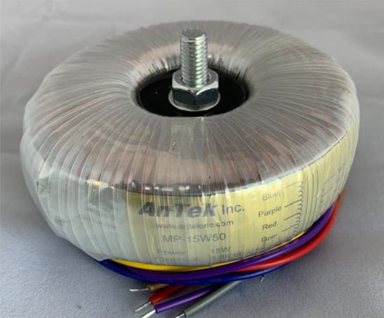
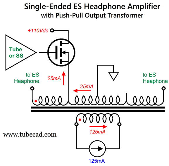
My Post 642 revealed how smitten I am with AnTek's 15W toroid push-pull output transformer, the MP-15W50 15W, as it not only delivered wide bandwidth but also includes purposely-made airgaps in it construction, making the transformer less susceptible to core saturation due to unidirectional current imbalance in its primary. This post also showed how a conventional electrostatic headphone could be driven by a single-ended amplifier that used the push-pull output transformer to increase the voltage swings.
The secret sauce here is that the transformer core never experiences a net magnetizing DC current flow through the primary and secondary, as the two DC current flows, being in opposition to each other, cancel.
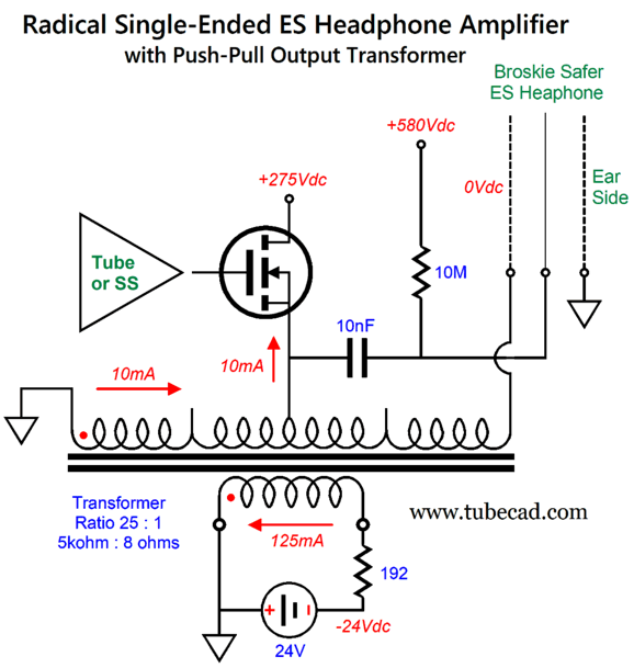
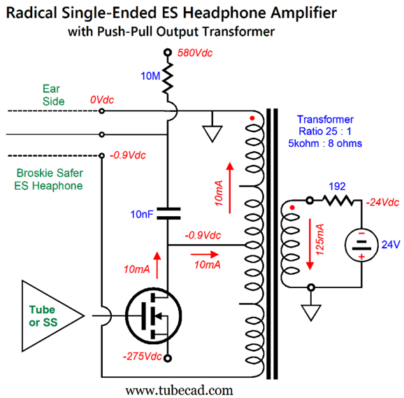
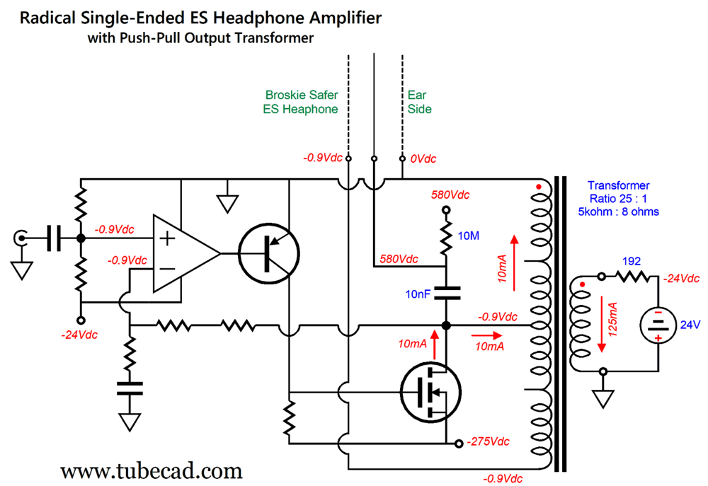
Well, if we transpose the MOSFET and the ground connection, we can drive my radical electrostatic headphones.
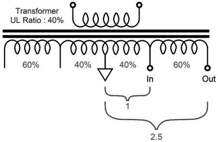
Let's start by noticing that the MOSFET's B+ voltage has increased, but its idle current has decreased. The MOSFET's source must undergo much larger voltage swings, but with smaller current swings. What is going on here? When the ultra-linear tap was driven, only 20% of the primary was directly driven. When the center-tap is driven, however, 50% of the primary is directly powered, making for a ratio of 1 to 2.5, so the idle current can be reduced to 25mA/2.5 or 10mA. In contrast, the driving the primary's center-tap requires the MOSFET's output voltage to swing 2.5 times higher, so the MOSFET's B+ voltage must be increased by 2.5 times, i.e. 275Vdc. Note that ultra-linear taps are not needed in my radical redesign, just a center-tap, which all push-pull output transformers hold (some single-ended output transformers hold an ultra-linear tap, which sometimes is placed at 50% of the primary winding, so these single-ended output transformers could be used in this circuit). The MOSFET experiences voltage swings both positive and negative, so the peak source-to-drain voltage can approach (or indeed exceed) its B+ voltage; therefore, I would use a 700V to 1kV N-channel MOSFET, possibly a SiC type. On the other hand, we could replace the MOSFET with a tube, either a pentode or triode. (Using a pentode could prove tricky, as a floating power supply would be needed to power the screen.)
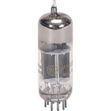
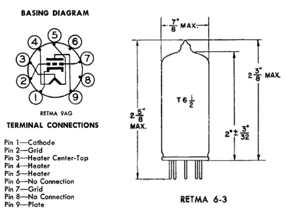
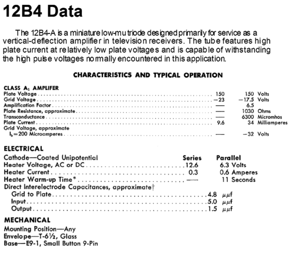
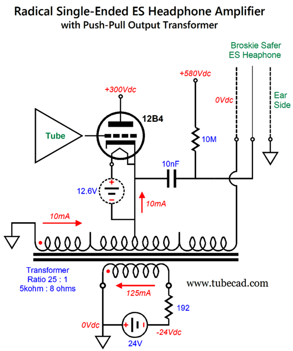
One possible triode is the 12B4 single-triode tube, which is a low-mu triode designed to work with extra-high voltages.
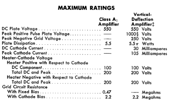
Its maximum peak-positive pulse voltage is 1kV. It will, however, require a floating power supply for its heater; one per channel.
The B+ voltage need only be upped to +300Vdc, as the triode can draw 20mA with a cathode-to-grid voltage of 0V and cathode-to-plate voltage of 28V. In other words, we should have no problem getting 250V voltage swings from the 12B4, although the 12B4 requires a huge input signal. We can also drive the center-tap with a MOSFET's drain.
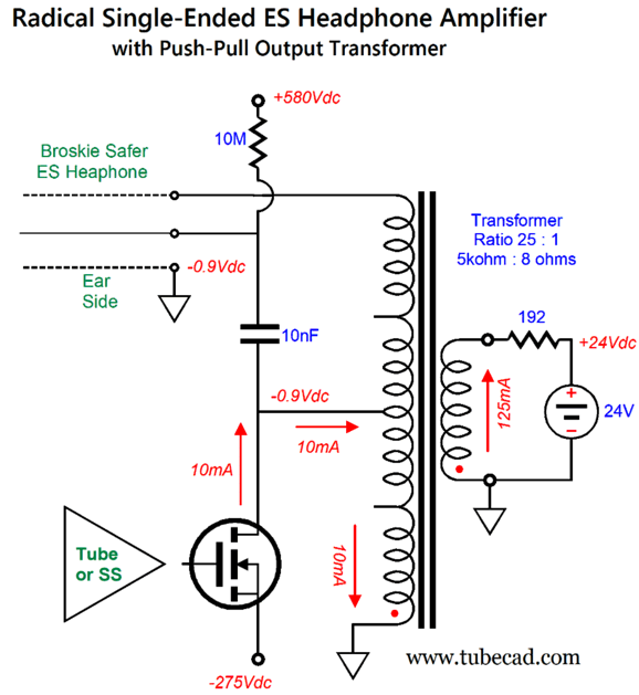
Note that the ear-side of the electrostatic headphone is grounded, as is the primary's top termination. By the way, we can invert the transformer, but we must also invert the 24V power supply's polarity.
Which arrangement is better? I prefer the former, as the negative 24V power supply can also power OpAmps.
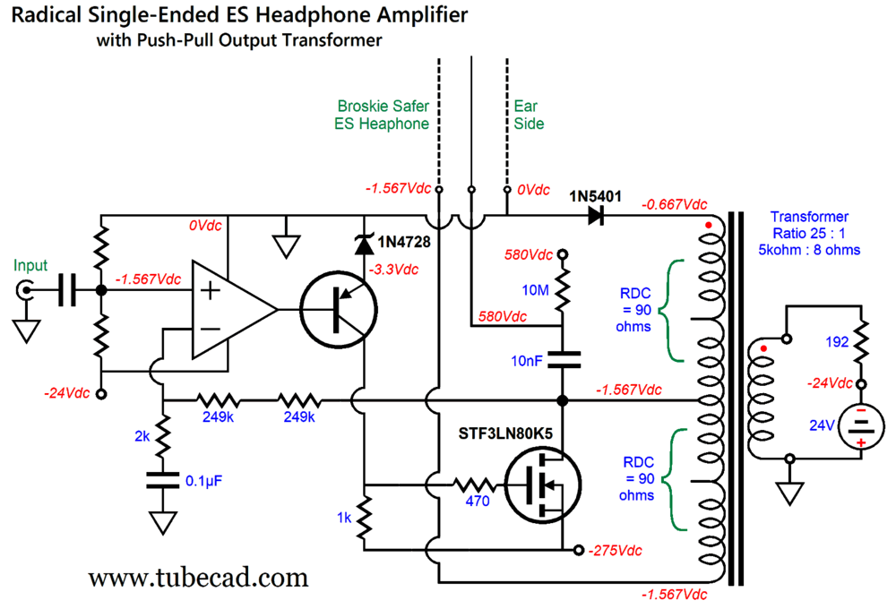
The OpAmp's noninverting input sees a bias voltage of -0.9Vdc, which is used to auto-bias the MOSFET's idle current flow, as the top half of the 180-ohm primary (i.e. 90 ohms) must experience the 0.9 volt voltage drop, making for a current flow of 0.9/90 or 0.01 or 10mA. One fear I have is that the OpAmp might not like having its inputs so close to it positive rail voltage. One workaround is to impose an additional fixed voltage drop.
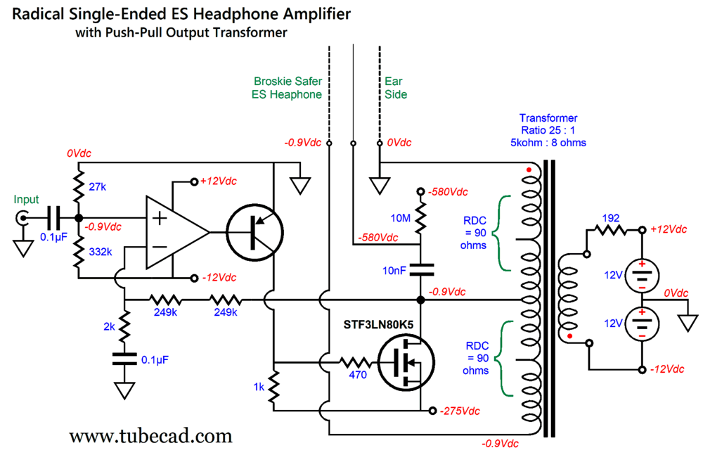
The inclusion of the 1N5401 rectifier buys us almost 0.7V more voltage drop. Of course, we could use a zener of voltage reference IC to make an even greater voltage drop, but at the cost of small bias voltage on the not-grounded stator. Okay, it's time to put on our thinking caps. We have the problem with many OpAmps not being happy with input signals near their positive power-supply rail voltage. We have an asset in the 24V power supply that provides the countervailing current flow through the secondary. Who says we cannot use a ± 12Vdc bipolar power supply instead? No one.
The secondary sees the current flow at idle, the OpAmps is happy with input signals near the center of its bipolar power supply voltages (i.e. 0V, making its input stage and output stage happy), and we no longer need to add rectifiers or zener diodes. Ideally, the 332k voltage divider resistor should be 333k, but 332k is dang close. (Of course, I assume a fully regulated bipolar power supply.) No doubt, some tweaking of the negative-feedback loop might be required and finding a high-voltage PNP transistor is difficult, but not impossible. Note the -580Vdc bias voltage for the diaphragm. This is a feature, not a bug, which my last post explains.
I rank this design worthy of half a Musk Prize Medal, but then—every mother's child is beautiful.
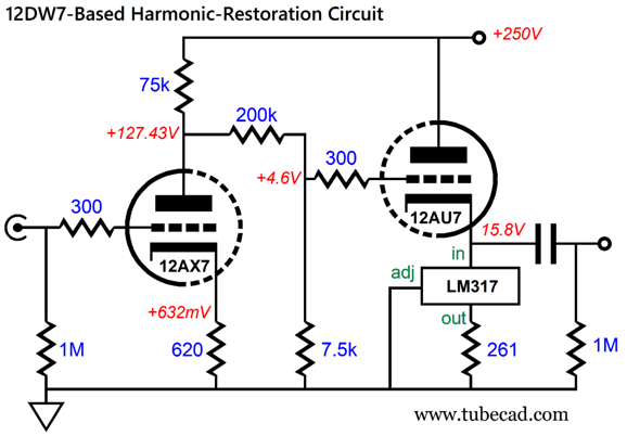
12DW7-Based Harmonic-Restoration Circuit
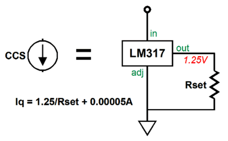
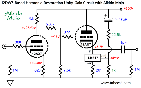
The 200k and 7.5k resistors form the two-resistor voltage divider. The LM317 functions as a constant-current source that sets the idle current flow for the 12AU7 triode.
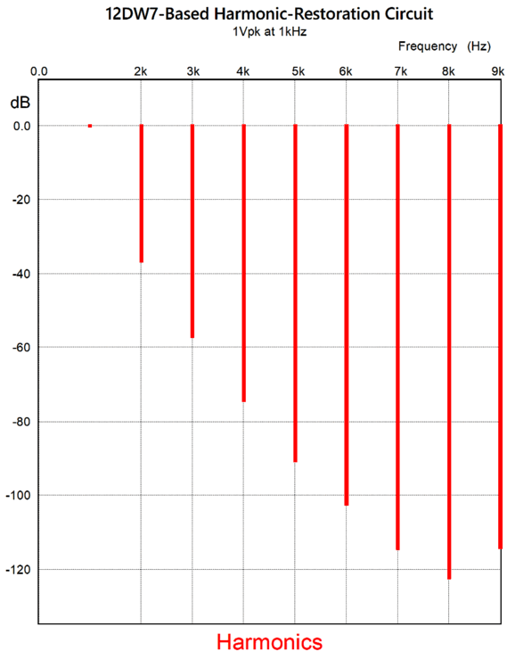
In SPICE simulations, this circuit delivered a healthy amount of harmonic-restoration to a 1Vpk output signal.
I overshot my goal of 1% distortion by only a tad. With an input signal of only 0.1Vpk, the distortion falls near to 0.1%, but still exhibits the single-ended cascade of harmonics. What I didn't like, however, was the relatively poor PSRR of only -22dB. Aikido Mojo to the rescue:
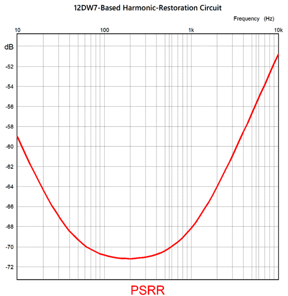
The constant-current source is no longer perfectly constant, as we have injected a small sampling of the power-supply noise into its adjustment pin, which induces an anti-phase current variation that nulls the power-supply noise at the cathode follower's output. Here is the SPICE-generated PSRR graph:
A nearly fiftyfold improvement. Nice! Mind you, this PSRR figure is only the base PSRR, which does not include the further PSRR-enhancements wrought from RC filters and LC filters or high-voltage regulation. Of course, the same topology can accept other tube types, such as the 6DJ8, 6SN7 and 12AU7… and many more. The part values and B+ voltage will differ, but the design concept remains the same: generate signal gain with a triode, attenuate, and buffer. By the way in this design, the LM317-HV is not required, but I could be with other tubes and different B+ voltages. I should point out that this harmonic-restoration circuit inverts the input signal's phase at its output. Is this a big deal? No, as you can simply flip the phase of the loudspeaker cable's connection to the speaker terminals. Of course, some audiophiles will still be bothered by the inversion. (If rational behavior were a strict requirement to be an audiophile, the number of audiophiles would be even more miniscule than it is now.) For such audio folk, here is a non-inverting harmonic-restoration circuit:
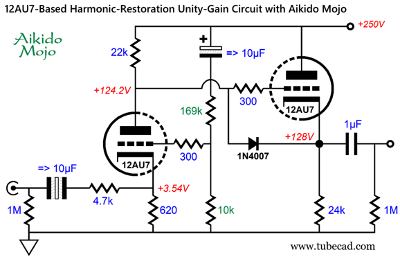
The input 12AU7 triode is configured as a grounded-cathode amplifier that gets its input signal at its cathode. It does not invert the input signal at its plate. The cathode follower output stage also preserves the phase of the input signal. The assumption here is that the circuit would follow some modern solid-state audio signal source, such as a CD player, tuner, DAC, or streamer, whose solid-state output stage can easily drive the 4.7k load resistance (almost all can). The signal-flow layout is that the input signal is attenuated by the 4.7k and 620-ohm resistors, and then amplified by the grounded-cathode amplifier and buffered by the cathode follower. To improve the PSRR, some Aikido Mojo has been included via the 169k and 10k two-resistor voltage divider, which delivers just enough of the power-supply noise to the grounded-cathode amplifier's grid to provoke a ripple null at the circuit's output. The 1N4007 rectifier is a safety device that only engages at startup, when the triodes are still cold and not conducting. Once the triodes are warm, the rectifier falls out of the circuit, as it is no longer forward biased. The input coupling capacitor shown is a nonpolarized electrolytic capacitor, but a film or PIO capacitor could be used instead. Although this harmonic-restoration circuit does produce some 2nd harmonic distortion, its quantity is low, as the THD approaches 0.01%, with 1Vpk of output, in SPICE simulations. The PSRR at 100Hz came in at a respectable -54dB. Using carbon resistors and PIO coupling capacitors might be enough to further flavor the output signal.
Disposable Suppressor Inserts In Post 471, I revealed one design idea I had, which made use of a only a metal lathe and standard metal piping.
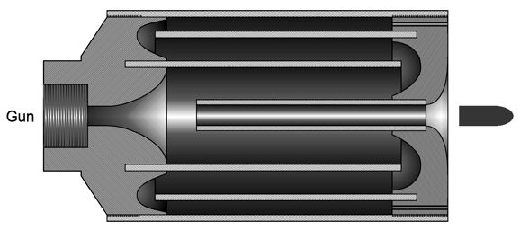
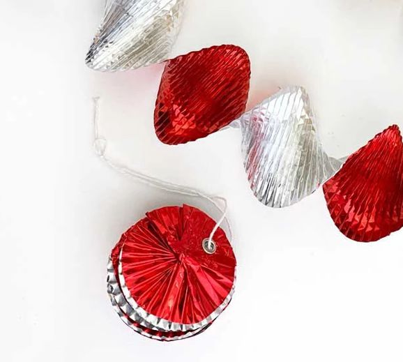
Basically, a suppressor is tubular enclosure with two openings and internal baffling. They tend to be insanely expensive, often costing more than the gun they intend to quiet. Why this is so is due, in part, to government regulations and restrictions, and the restraints and inefficiencies of small production. More importantly, I believe most suppressors are excessively overbuilt, often using expensive titanium or advanced 3D printing or elaborate machining construction. Why? One reason is that they are usually designed to survive automatic fire of serious ammo. Moreover, like sports cars and racing boats, suppressors are designed by men, the sort of men who naturally incline to showing off and who strive for excellence. The reality, in contrast, is that few guns are ever used. (A friend has owned his revolver for decades, but never has fired a shot from it. He is not alone in this.) Those few guns that are used are only rarely used, say once a year, and thereby expending only one box of 20 or 50 rounds. These guns do no need a military-grade suppressor. What they do need is a good, but cheap suppressor, preferably one that accepts replaceable inserts, which might only survive 500 rounds—in other words, survive a decade's worth of casual shooting. The insert could be made from porous lava stone or a coil of copper screen rolled into a tube and welded tight. One thought I had was that of a variation on the metal-foil Virvateller expandable garlands, but made from more solid aluminum.
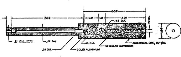
Same principle, a long narrow strip of metal is crinkled and rotated into a disk, but with a center hole drilled through to allow the bullet free travel. We could buy a pack with four disks for let's say $40; we would begin by pulling the disk's ends apart to create a spiral, a spiral slightly longer than the suppressor tube's inner length, which we would insert into the suppressor tube, and screw the end cap in place, replacing the insert as needed. The outer tube could be made from titanium or hardened steel. John, don't seem to realize that suppressors are used to kill people? Really? Have they been fired from cannon, dropped from a skyscraper? No, but they are used with guns. Okay, by the same logic, scopes, tripods, slings, red-dot sights, gun oil, and ear muffs are also used to kill people, yet we do not outlaw them or restrict their manufacture. Do you think we should? If so, what about the car that was used to bring the gun? Back in the 1960s, Frankford Arsenal developed a cheap, disposable suppressor:
From page 31 of the Frankford Arsenal Report R-1896
Music Recommendation:James Blake's James Blake Wow! I didn't expect that. I won't ruin the surprise, so you must stream it and find out what all the buzz is about. //JRB
Did you enjoy my post? Do you want to see me make it to post 1,000? If so, think about supporting me at Patreon.
AI Summary This document discusses innovative designs and modifications for electrostatic headphone amplifiers, focusing on push-pull transformer configurations and power supply considerations. Innovative Electrostatic Headphone Designs
Push-Pull Transformer-Driven Headphone Amplifiers
Advanced Harmonic-Restoration Circuits
Disposable Suppressor Insert Concepts
Music Recommendation: James Blake's Album
User Guides for GlassWare Software
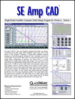
For those of you who still have old computers running Windows XP (32-bit) or any other Windows 32-bit OS, I have setup the download availability of my old old standards: Tube CAD, SE Amp CAD, and Audio Gadgets. The downloads are at the GlassWare-Yahoo store and the price is only $9.95 for each program. So many have asked that I had to do it. WARNING: THESE THREE PROGRAMS WILL NOT RUN UNDER VISTA 64-Bit or WINDOWS 7, 8, and 10 if the OS is not 32-bit or if it is a 64-bit OS. I do plan on remaking all of these programs into 64-bit versions, but it will be a huge ordeal, as programming requires vast chunks of noise-free time, something very rare with children running about. Ideally, I would love to come out with versions that run on iPads and Android-OS tablets.
|
I know that some readers wish to avoid Patreon, so here is a PayPal button instead. Thanks. John Broskie
John Gives
Special Thanks to the Special 89 To all my patrons, all 89 of them, thank you all again. I want to especially thank
I am truly stunned and appreciative of their support. In addition I want to thank the following patrons:
All of your support makes a big difference. I would love to arrive at the point where creating my posts was my top priority of the day, not something that I have to steal time from other obligations to do. The more support I get, the higher up these posts move up in deserving attention.
If you have been reading my posts, you know that my lifetime goal is reaching post number one thousand. I have 357 more to go. My second goal was to gather 1,000 patrons. Well, that no longer seems possible to me, so I will shoot for a mighty 100 instead. Thus, I have just 11 patrons to go. Help me get there. Thanks.
New URL of the GlassWare website |
||||











| www.tubecad.com Copyright © 1999-2026 GlassWare All Rights Reserved |