| John Broskie's Guide to Tube Circuit Analysis & Design |
16 July 2019 Post 471
OTL and Differential Phase Splitters
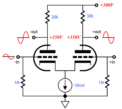
If you are mathematically inclined, you can easily work out that the differential phase splitter can deliver the same maximum voltage swings of a split-load phase splitter's but with far less B+ voltage, the difference being found in the horizontal arrangement (parallel) of triodes in the differential phase splitter compared to the vertical arrangement (series) of the split-load phase splitter. The best approximation would be twice the B+ voltage and twice the rp. Moreover, the differential phase splitter creates signal gain, which the split-load phase splitter can't do other than deliver two anti-phase signals that sum to almost 2. It's best to let triodes create gain, if we wish to retain as much tube flavor as possible. In other words, other than less cost and greater longevity, there is no compelling reason to use a transistor in differential phase splitter. Using a tube-based differential phase splitter, however, does not necessarily guarantee that our OTL is solid-state free, as the differential phase splitter works best when its tied cathodes are loaded by a constant-current source, which are usually solid-state designs.
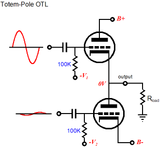
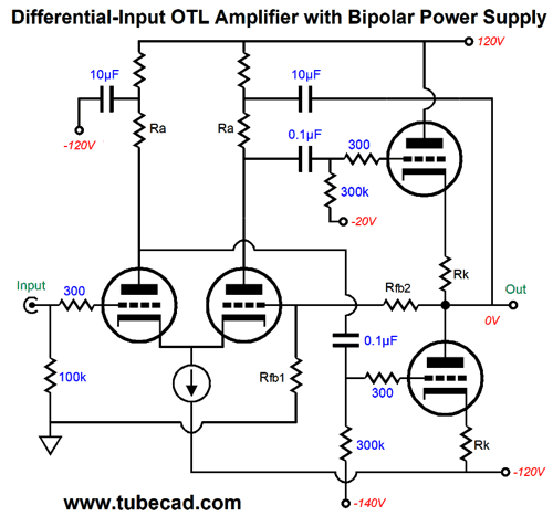
In an OTL amplifier, the phase splitter must perform two essential tasks: convert an unbalanced input signal into balanced pair of output signals and ensure equal and opposite current swings from the output tubes. In addition, it's the phase splitter's configuration that determines the output tube's mode of operation, either cathode follower or grounded-cathode amplifier. This means that the output signal must be returned to the differential phase splitter so that the phase splitter can incorporate the output signal into its outputs. Fortunately, the output signal can be returned with a single capacitor.
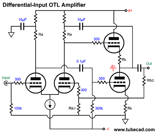
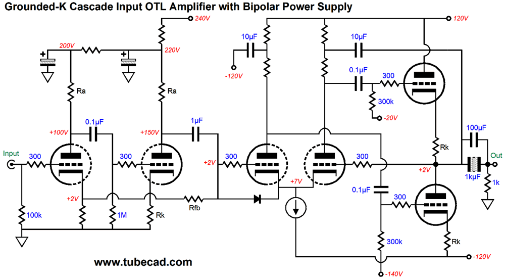
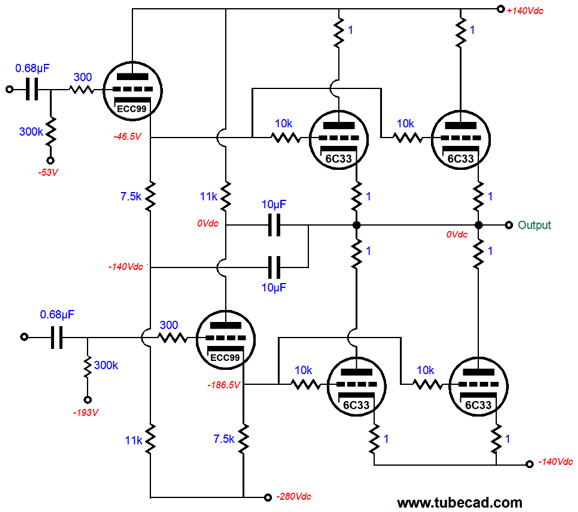
The 10µF capacitor on the right relays the output signal to the top of the plate resistor, while the 10µF capacitor on the left shunts the power-supply noise to ground. The top output triode is DC coupled to the phase splitter and the bottom triode is capacitor coupled to it. The output stage uses fixed bias and the two cathode resistors are small in value and are used to allow easy current-flow measurements and to prevent current hogging when multiple output tubes are used in parallel. (If one output tube draws too much current, the cathode resistor will develop a greater voltage drop, which will tend to auto-correct its exuberance.) If nothing else, the cathode resistors function as fuses, should an output tube arc or short, protecting the loudspeaker. Two negative feedback resistors, Rfb1 & Rfb2, are used to create a global negative feedback loop that encompasses the output stage and the phase splitter. In other words, this is a complete amplifier. Here is a design example:
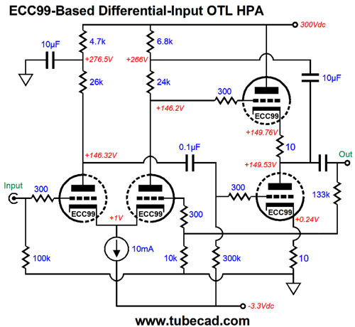
This is a mini OTL amplifier for driving headphones, whose impedances vary from 75 to 600 ohms. To drive lower impedance or less efficient headphones, more output ECC99 must be placed in parallel. The output stage idle current is a heavy 24mA, which will allow peak class-A current swings of 48mA, which into a 100-ohm load would equal peak voltage swings of 4.8V. The peak class-AB current swing would be about 60mA. How do we find this value? The formula is Ipeak = (B+ voltage) / 2(rp + Rload + Rk) The ECC99 exhibits a plate resistance of about 2300 ohms. Assuming a B+ voltage of 300Vdc and load impedance of 100 ohms, we divide 150V by 4820 ohms. Note in the schematic the dissimilar plate resistor values, 26k and 24k. Why? The answer is found by placing 26k in parallel with 300k, which is the grid-bias resistor value, which yields 23.926 ohms, dang close to 24k. Also note how the top resistor values were chosen to compensate for the differing plate resistor values, as 26k + 4.7k comes close to 24k + 6.8k. Had I not purposely limited myself to 5% resistor values, using 1% values instead, we could have closer to a perfect match of plate voltages. I didn't include the output coupling capacitor value, but we can easily find the required value with the following formula: Capacitor = 159155/Frequency/Rload where is the capacitor value is in µF and Rload is the load impedance. For example, assuming 20Hz and 300 ohms, we need 26.5µF, which we would round up to 30µF. The output triodes run in grounded-cathode-amplifier mode, so the negative feedback loop is needed to lower the output impedance. With a solid-state amplifier, the negative feedback resistor values imply a fixed gain of 14.3 or +23dB. But with tubes, the amplifier is so weak in transconductance that we never get the full gain implied by the feedback-resistor ratio. In this example circuit, with a load impedance of 300 ohms, the gain comes in at 10 or +20dB; with a 100-ohm load, 8.84 or +18.9dB. The output impedance is about 28 ohms. Okay, after this warm-up, we can move on to OTL with bipolar power supplies.
Things look fairly similar to the previous version. Yet, there are several important differences. For example, note the absence of an output coupling capacitor. This is why most want to use a bipolar power supply, so no output coupling capacitor is needed. The fear is that although we lost the output transformer, we gained an output coupling capacitor, which can only subtract sound quality, as less is always more in audio circuits. Is this true? I have known audiophiles who purposely added PIO coupling capacitors to solid-state audio equipment, so they smooth-up the output signal. If we conduct an AB audio test with coupling capacitor versus no coupling capacitor, how much money would you be willing to bet on which result would be preferred. I wouldn't make a bet one way or the other. Do cars look better painted or with bare metal? Do meals taste better without spices or with? Are sunny days more bearable with or without sunglasses? Finally, are people more attractive with or without clothes? The best answer is that it depends. What is not controversial is that a coupling capacitor is far safer than a DC connection. Why? In order to get the require current swings out a tube, we must run crazy high B+ voltages, usually four or five times greater than what a solid-state power amplifier that deliver the same wattage would need. High-voltages and loudspeaker longevity do not go together. A brief arc in one output tube will connect the loudspeaker to one of the bipolar power supply rails. Not good. I have seen 6550 output tubes in a transformer-coupled amplifier glow cherry red and melt down. Now imagine the same thing with a direct coupled OTL amplifier. A nightmare. Fifty years ago, it was much easier to argue against a large-valued coupling capacitor, as the electrolytic capacitors were truly dreadful, with the possible exception of photo-flash capacitors. Today, electrolytic capacitors are better. In fact, I would say that in the last ten years I have been impressed by their increased quality. In years past, I would charge up an electrolytic capacitor and it would self-discharge in minutes, if not seconds. Today, the new capacitor takes hours to self-discharge. Think about this: three decades ago, most electrolytic capacitors were used in power supplies, where the ripple frequency was 120Hz. Today, most are probably used in switcher power supplies or in digital circuits, which require far better high-frequency performance. There was also the scandal of bad electrolytic capacitors taking out computer motherboards about a decade ago, which prompted the entire capacitor industry to address the issue of reliability. In short, electrolytic capacitors had to become vastly better, because their applications had become more demanding. In addition, high-value polypropylene capacitors are no longer rare and can readily be bought. For a coupling capacitor to go down to 20Hz with an 8-ohm load, the capacitance must at least equal 995µF. Well, eight 130µF polypropylene capacitors in parallel would get us there. Moreover, non-polarized electrolytic capacitors sound far better than the more common polarized electrolytic capacitors. (I quite like those made by Panasonic.) We can place ten 100µF/50V non-polarized electrolytic capacitors in parallel with one 100µF/250V polypropylene capacitor, which we can further sweeten up with additional PIO bypass capacitors.
Autoformers in OTLs
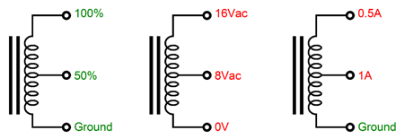
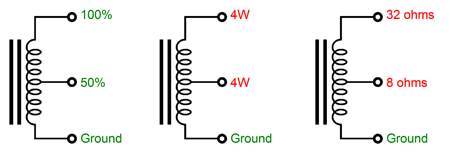
A center-tapped autoformer winding yields a voltage ratio of 2:1 and a current ratio of 1:2 and an input ratio of 4:1. In other words, we would get half the voltage swing from the OTL, but twice the current swing and the 8-ohm loudspeaker would appear as a 32-ohm load to the OTL output stage.
If the output tap were taken at the bottom third of the autoformer winding, the voltage ratio would be 3:1; the current ratio, 1:3; and the impedance ratio, 9:1, so an 8-ohm load would appear as 72 ohms. If an output coupling capacitor were used with an autoformer in a totem-pole arranged OTL, the capacitor value for a 72-ohm load would be a low 110µF. In addition, autoformers are half the size of an equal power transformer. A 72-ohm load autoformer should exhibit an inductance of 1H from end to end.
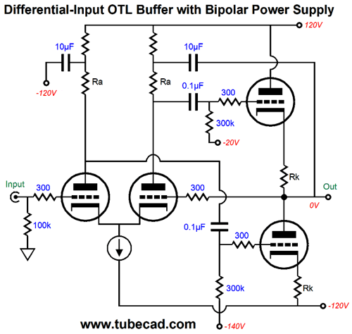
OTL Power Buffers
The only difference between this power buffer and the same OTL power amplifier is that negative feedback returns 100% of the output signal to the differential input stage. One subtlety here is that the constant-current source must be connected to a negative power-supply rail voltage greater than the largest expected output voltage swing, as the tied-together cathodes will follow that output voltage swing. In other words, we cannot just ground the constant-current source, which we might have been able to pull off in the amplifier version, depending on the input tube used.
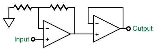
I mentioned nesting the unity-gain power buffer within a larger amplifier circuit, which would allow wrapping a global negative feedback loop from output to input. My preference would be to cascade two circuits, a gain stage with its own negative feedback loop and a power buffer with its own negative feedback loop. Why? Although this cascade results in higher distortion and output impedance, I believe the sonic results are worth it the exchange. We start with the observation that the more circuitry inside the negative feedback loop, the harder it is to achieve stability, due to the compounding phase shifts; and we end with the realization that all power amplifiers clip. With one big complex OTL amplifier circuit, recovery from clipping requires all the components to fall back in line. In contrast, with the amplifier-buffer cascade, only the buffer stage clips and must recover, as the amplifier gain stage doesn't clip, as it can produce far larger output voltage swings than the buffer can deliver into a loudspeaker. Here is an example:
The amplifier stage consists of two grounded-cathode amplifiers in cascade, with a negative feedback loop returned to the input triode's cathode. Since the negative feedback resistor is capacitor coupled to the second triode's plate, a DC offset is present at the differential amplifier's input grid, which in turn should be met with the same DC offset at the output stage's output. Thus, the large-valued output coupling capacitor. The diode is there to protect the differential phase splitter at startup, so the input grid is not 120V more positive than the cathodes. Under normal operation, the diode is reversed biased and drops out of the circuit. Another possible input stage would be the cathode-coupled amplifier.
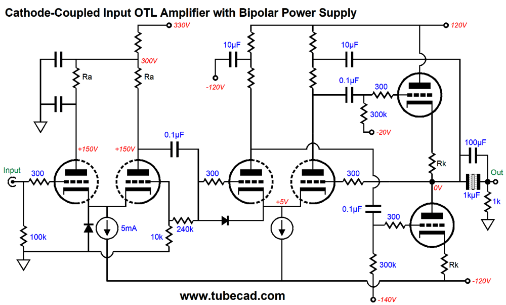
The cathode-coupled amplifier takes advantage of the negative power-supply rail voltage. It, too, gets a protection diode. Its output is fed back through the negative feedback resistors, 240k and 10k. We would want only enough negative feedback to overcome tube to tube differences and tube ageing. In other words, very little negative feedback. A good input tube choice might be the 12AT7. The buffer stage's differential amplifier is protected by a diode, which will limit the maximum positive grid-to-cathode voltage to about 0.7V. The output is once again capacitor coupled for safety reasons, although it could be DC coupled, as the differential input sees no DC offset. Another workaround would to be use a time-delayed relay to short the output tube grids to the cathodes at startup up.
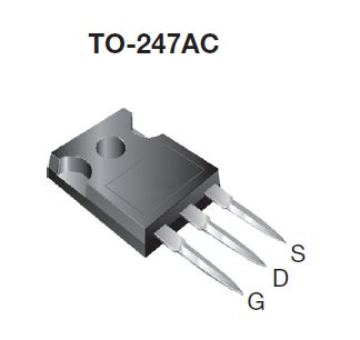
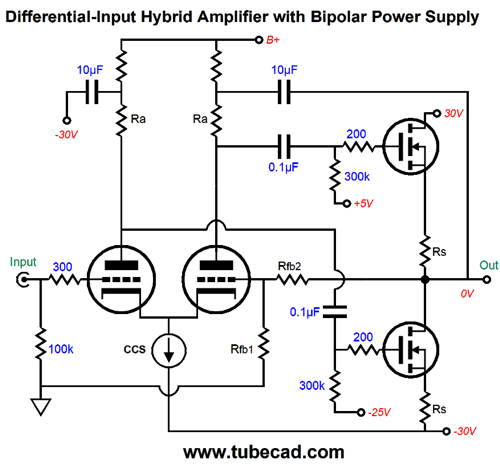
By the way, the differential phase splitter can be used in a hybrid amplifier that uses power N-channel MOSFETs in the output stage.
Note that since the MOSFET is a depletion-mode device, which must see a greater gate voltage than its source voltage to conduct, the biasing of the MOSFETs can be done within the confines of the +/-30V bipolar power supply. In fact, we can easily add a DC servo to keep the output centered at 0V.
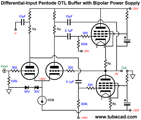
Pentode OTL Output Stages
Both output pentodes will have to drive the top pentode's screen resistor as load resistance in parallel with the loudspeaker impedance. Note the current-flow differences between top and bottom pentodes. The bottom pentode must supply the needed current for both its screen resistor and the top pentode's screen resistor, while the pentode only has to source the current for its screen resistor. In other words, the bottom pentode will work slightly harder than the top pentode. One workaround is to add two cathode followers in between the differential phase splitter and the output tubes.
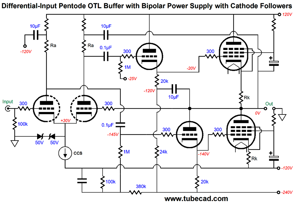
This arrangement looks somewhat similar to that of the Brazilian OTL amplifier shown in posts 416 and 417, but differs in that the cathode follower that drives the bottom pentode's grid sees its plate terminate into the output stage output, not an 11k plate resistor.
Since the Brazilian OTL circuit used a 10µF capacitor to AC connect the bottom cathode follower's plate to the output swings, both circuits are the same in AC terms. They differ, however, in DC terms, as the bottom cathode follower now provides the current path for the top pentode's screen resistor, because the its plate terminates directly into the output, thereby unloading the bottom pentode of the task. Okay, how many reader's heads just exploded. I wish were all in one room and I could see your facial expressions. The following schematic should help make this point more clear.
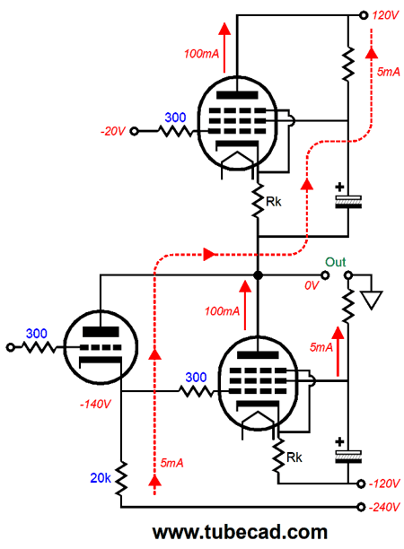
Let's assume that the screen resistors draw 5mA and that the cathode followers do the same. The bottom cathode follower's current flows up through its plate into the output and then up through the top cathode resistor and through top pentode's cathode to its screen and then up through the top screen resistor to the positive power-supply rail connection. Thus, both pentodes see the same plate cathode and plate current flows, the cathode current flow being 5mA greater than the plate current flow. So how does the bottom cathode follower complete its current flow when the top pentode completely shuts off? The external load resistance, i.e. the loudspeaker. What about when the bottom pentode cuts off? The bottom cathode follower still conducts through the top pentode's cathode. Not shown is the need for a separate heater power supply for the top output pentode and its cathode follower. Since two pentodes are not likely to prove sufficient, most OTL amplifiers would use at least four output tubes, if not six or eight. I would give each output tube its own cathode follower and I would reference the top output tubes and top cathode follower triode heater elements to the output, while the bottom output tubes and cathode follower triode heater elements would be referenced to the negative power-supply rail. When the output tubes are driven into positive-grid voltage, the grids will define a rectifier with the cathode and begin to conduct current, which the cathode followers will deliver. During the positive-grid operation, the cathode follower will indirectly help power the loudspeaker, as their increased current flow will flow in and out of the loudspeaker. Admittedly, this cathode-follower arrangement is subtle, but then great power amplifiers are made from many subtle improvements. With a tube-based OTL amplifier, we already start with huge liabilities, so these many subtle improvements are all the more important.
Shush! In Europe, however, shooting a gun without a silencer is bad manners. In France (for rimfire pistols only), New Zealand, Norway, and Poland, no permit is required and they are just sold in gun stores. In Denmark, Finland, Germany, Great Britain, Hong Kong, and Sweden, if you have a permit to buy a gun, you are also permitted to buy a silencer. I have heard that hardware stores in South Africa sell silencers just as if they were hammers or any other tool. Today, air guns have gotten so powerful, i.e. so loud, that many come pre-equipped with a silencer.
The question, why are they so overbuilt, using thick steel or titanium? is answered by necessity. A silencer made of steel will last about five times longer than the barrel; a titanium silencer, ten times longer. Fire a gun once and the silencer will warm. Fire it ten times and the silencer will be too hot to safely touch. Fire it a few hundred times and the silencer might glow and deform. Remember that the hot expanding gasses rip through the high-resistance baffling before exiting, transferring much of their energy to the silencer. I wonder: has anyone invented a water-cooled silencer?
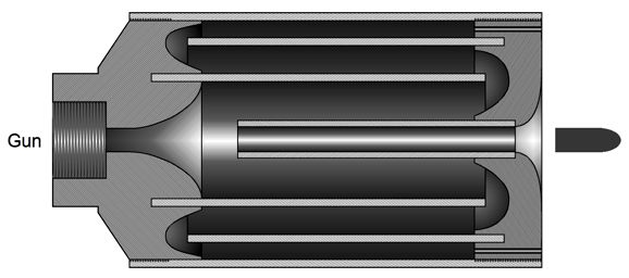
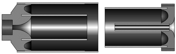
In researching silencers, I discovered that I could legally buy one here in Colorado, but that it takes a year before the federal government approves the sale of the silencer stamp ($205) and that once I obtain the stamp, only I can use the silencer. The legal workaround here is to create a trust, with all my family in it, so the trust can buy the stamp and we could all use it legally. I actually wanted to make my own silencer, not buy one, but the same laws apply and the stamp must still be bought and approved. I also discovered that silencers are directional. Some are designed to protect primarily the shooter's hearing, while other are designed to be quieter at the receiving end. The most unpleasant silencers are those that blow the hot gasses towards the shooter face. I discovered that silencers do not necessarily degrade the gun's accuracy nor limit the bullet's velocity. In fact, they sometimes increase it. I also read that the attenuation of the gun's report was not all that great, nothing like what we have heard in movies, being only attenuated by 25 to 35 decibels, roughly the same as wearing high-quality ear protectors. But if we combine both, shooting would prove far more pleasurable. The design I had in mind would require a metal lathe and metal tubes and some copper screen to make. Here is a cross-sectional slice view of what I have in mind.
The gun's barrel would be tapped so the silencer could screw on. Much like a transmission-line loudspeaker cabinet, this silencer would provide a long path that would both delay much of the hot gas's exit, but cool it as it moves through a rolled up copper screening, which was not included in the drawing. Since, I would only want to silence a 22-caliber pistol, steel end pieces and tubing would be sufficiently strong. Since the silencer must be thoroughly cleaned after use, easy disassembly is essential, which is why I like the idea of treaded end pieces and metal pipes (tubes).
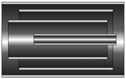
If the design doesn't seem to make sense, just start with the four pipes (i.e. metal tubes).
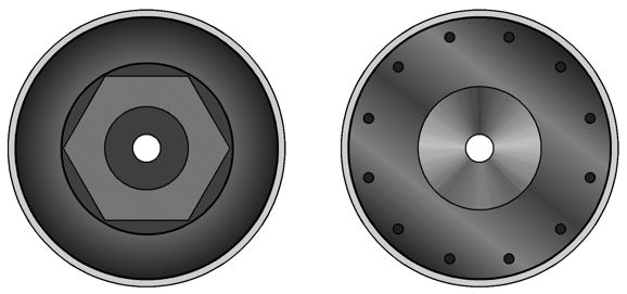
Then add the two end-caps. An actual silencer based on this design would be much thinner. I purposely made the drawing of it fatter to better show the gas passages. The front end-cap, shown on the right below, holds a circular array of small exit holes. The end that attaches to the gun's barrel would have a milled hex so the silencer could be firmly attached to the gun with a wrench.
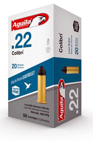
In my research, I discovered special low-noise 22 bullets that are made in Mexico, Aguila Colibri Ammunition 22 long-rifle 20 grain solid point bullets, that hold no powder, only primer charges. They will not cycle a semi-automatic pistol or riffle and if the rifle barrel is too long, they won't leave the barrel. I have been told that their report sounds like a child's cap-gun. They also sell another subsonic version that packs more punch.
Alternatively, American-made CCI's Quiet-22 40 grain bullets are loaded in standard 22 long-rifle rimfire cases and are said to be quieter than actual silencer equipped guns, coming in at only 74 decibels from a 6-inch pistol barrel, which is amazing. In contrast, high powered air rifles come in at over 110 decibels.
Obviously, this bullet is subsonic and it may not cycle all semi-automatic guns; still, it delivers 40 foot pounds of energy at 50 yards. Now, imagine firing a single-shot pistol, such as the Thompson/Center G2 Contender, with CCI's Quiet-22 bullets and a silencer. By the way, if you wish to improve your shooting ability, train on a single-shot gun, as reloading each shot is a pain, so you will make each shot worth the effort. (The best shot I have ever known took ten times longer than anyone one else to fire each shot, as he had to both quell his body and become entirely aware of his body, his breathing, his tensions, his mental calm. His clusters started in a 2-inch group and kept tightening until he arrived at the gun's intrinsic limit, which could be found by firing the gun repeatedly from a rubber-lined vice.)
Music Recommendation: Jazz Bass Music
The album, Super Bass, features three jazz bass players, Ray Brown, John Clayton, and Christian McBride. It's on the Telarc label and certainly audiophile grade listening. Moreover, it's fun. The last album, Eeg - Fonnesbæk, is duet made up of the Danish jazz singer Sinne Eeg and the Danish jazz bassist Thomas Fonnesbæk. I was impressed by how well she sang. His bass playing, like her singing, is wonderfully tidy and refined. The urge to over do it, to ham it up, to fall into tasteless travesty must be great, so the two should be saluted for avoiding this trap. Put those subwoofers to work, listen to more bass players. As always, all four albums are available at Tidal. (No, I do not get a kick-back or discount or anything other than streamed music from Tidal.)
//JRB
User Guides for GlassWare Software Since I am still getting e-mail asking how to buy these GlassWare software programs:
For those of you who still have old computers running Windows XP (32-bit) or any other Windows 32-bit OS, I have setup the download availability of my old old standards: Tube CAD, SE Amp CAD, and Audio Gadgets. The downloads are at the GlassWare-Yahoo store and the price is only $9.95 for each program. http://glass-ware.stores.yahoo.net/adsoffromgla.html So many have asked that I had to do it. WARNING: THESE THREE PROGRAMS WILL NOT RUN UNDER VISTA 64-Bit or WINDOWS 7 & 8 or any other 64-bit OS. One day, I do plan on remaking all of these programs into 64-bit versions, but it will be a huge ordeal, as programming requires vast chunks of noise-free time, something very rare with children running about. Ideally, I would love to come out with versions that run on iPads and Android-OS tablets.
|
Special Thanks to the Special 86!
I am truly stunned and appreciative of their support. In addition I want to thank the following patrons:
All of your support makes a big difference. I would love to arrive at the point where creating my posts was my top priority of the day, not something that I have to steal time from other obligations to do. The more support I get, the higher up these posts move up in deserving attention. Only those who have produced a technical white paper or written an article on electronics know just how much time and effort is required to produce one of my posts, as novel circuits must be created, SPICE simulations must be run, schematics must be drawn, and thousands of words must be written. If you have been reading my posts, you know that my lifetime goal is reaching post 1,000. I have 532 more to go. My second goal is to gather 1,000 patrons. I have 914 patrons to go.
The Tube CAD Journal's first companion program, TCJ Filter Design lets you design a filter or crossover (passive, OpAmp or tube) without having to check out thick textbooks from the library and without having to breakout the scientific calculator. This program's goal is to provide a quick and easy display not only of the frequency response, but also of the resistor and capacitor values for a passive and active filters and crossovers. TCJ Filter Design is easy to use, but not lightweight, holding over 60 different filter topologies and up to four filter alignments: While the program's main concern is active filters, solid-state and tube, it also does passive filters. In fact, it can be used to calculate passive crossovers for use with speakers by entering 8 ohms as the terminating resistance. Click on the image below to see the full screen capture.
Tube crossovers are a major part of this program; both buffered and un-buffered tube based filters along with mono-polar and bipolar power supply topologies are covered. Available on a CD-ROM and a downloadable version (4 Megabytes). |
||


%20Cover.jpg)


| www.tubecad.com Copyright © 1999-2019 GlassWare All Rights Reserved |