| John Broskie's Guide to Tube Circuit Analysis & Design |
| June 17 2026 | Post Number 641 |
||||
Crossovers for Class-D Amplifiers
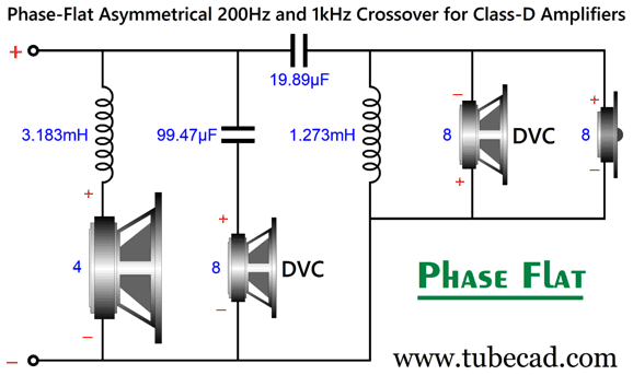
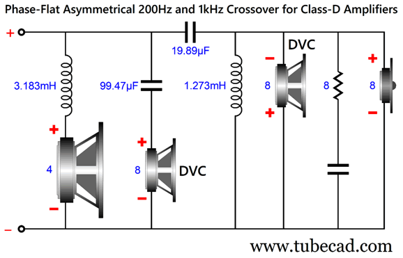
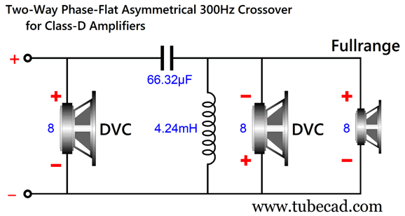
The dual-voicecoil driver (DVC) must have one of its voicecoils—the one that is in parallel with the tweeter—wired in opposite phase to its other voicecoil. Why? The out-of-phase voicecoil counters the high-frequency signals as it cancels the in-phase high-frequency signal the other voicecoil sees. Think of it as a free low-pass filter. By the way, we should add a Zobel network across the DVC and tweeter to null the DVC voicecoil's inductance (Le).
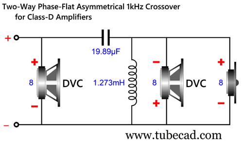
In fact, we should place a Zobel capacitor and resistor across both DVC voicecoils, but not across the woofer, as its Le works with us, as we subtract its Le from the calculated inductance. Ideally, DVC drivers with low series inductance would be used, but as so few DVC drivers are available, we must take what we can. Okay, I must add a further qualification to the last sentence, as many DV subwoofer drivers are made, but few DVC woofer-midrange drivers are made. Let's look at a two-way version (without any Zobel network), as it reveals how we cheated the system.
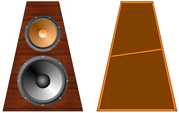
The only crossover shown, the capacitor and inductor, is a 2nd-order Linkwitz-Riley high-pass filter for a 4-ohm load. Where is the DVC woofer's crossover? It uses the high-pass filter and its one out-of-phase voicecoil to create the lumpy 1st-order low-pass filter that results in a flat-phase, transient-perfect crossover that still offer 2nd-order protection to the tweeter. This is a huge freebee, which is only possible due to the proliferation of cheap, small class-D amplifiers. Such a setup could prove a huge boon in car-audio and powered-loudspeaker systems, where a midrange-tweeter driver replaces the typical 1-inch dome tweeter. Speaking of fullrange drivers, I mentioned that speaker catalogs are replete with DVC subwoofer drivers, so why not use one with a fullrange driver?
For example, a 5-inch fullrange driver and a 6-to-8-inch DVC subwoofer would make a felicitous pairing, as the fullrange driver on its own stubbles at deep bass reproduction. Internally, the enclosure holds a divider that gives each driver its own sealed internal air volume. Note the wonderfully non-parallel walls. (The driver magnet structure itself serves to break up the rear wall reflections.) Here the crossover values for a 300Hz crossover.
I omitted Zobel networks for greater clarity. In my Post 636, I pointed out:
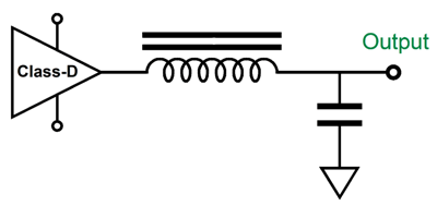
From International Rectifier's (Infineon Technologies) PDF, AN-1198 Class D audio amplifier ICs - Bridging class D amplifiers, we read:
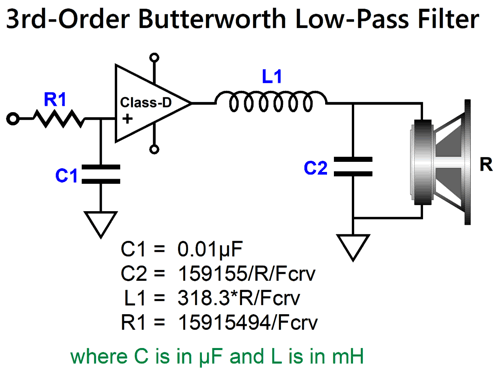
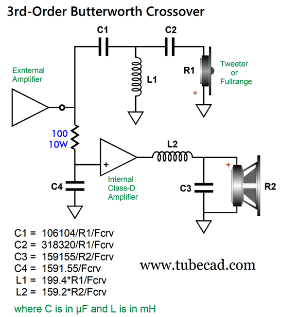
Well, what if we forgo the cheesy output inductors and capacitors and use high-quality (purposeful, more useful) inductors and capacitors instead? In other words, why not include the necessary inductor and capacitor within a passive crossover, moving the 40kHz low-pass filter down to, say, 400Hz? For example, here is a 3rd-order Butterworth low-pass filter:
The RC filter (R1 and C1) are tuned to the crossover frequency, while the output inductor and capacitor are also tuned to the crossover frequency, but with a Q of 1, which multiplied against the input low-pass filter's Q of 0.707, yields a final Q of 0.707. If a 2nd-order Linkwitz-Riley low-pass filter is desired, we simply omit capacitor C2, as all the math remains the same. Actually, I take that back, as we could subtract the woofer's Le from inductor L1's value. For a 1st-order low-pass filter, we can omit both L1 and C2, as the woofer's Le would probably be sufficient to filter away the 400kHz switching frequency. This would work well with a bi-amplified system, but in an augmented loudspeaker system that includes a powered woofer from an internal class-D amplifier, problems arise. For example, if an external power amplifier drives the loudspeaker, the load impedance the external power amplifier sees will not be flat, as the impedance rises to near infinity at ultra-low frequencies and reaches infinity at DC. A rising low-frequency impedance is seldom a big deal for a solid-state or OTL power amplifier, but it can be a big one for a transformer-coupled, tube-based one. Here is a partial workaround:
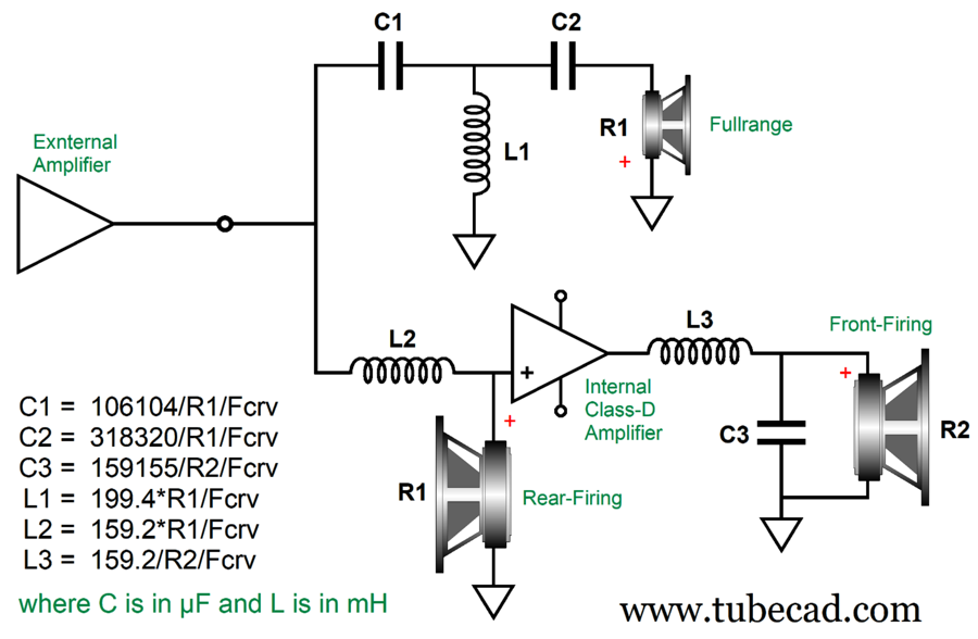
We use a 100-ohm power resistor for R1, the external power amplifier has more to bite on at low-frequencies. If we used an inductor and resistor, we would have to use a huge and expensive power resistor. A better and more interesting workaround would be to use two woofers, with one firing rearwards from the back of the enclosure.
A front and back set of woofers overcome the low-frequency cabinet diffraction loss and cancels the back-and-forth cabinet motion, as both woofers work in phase but in opposite directions. (As that pesky Newton's Third Law of Motion informs us, for every action there is an opposite reaction.) The rear-firing woofer experiences a 1st-order low-pass filter, while the front-firing woofer sees a 3rd-order low-pass filter. This means the rear woofer's phase departs from the front woofer's at higher frequencies. But as the woofers become more directional as the frequencies climb upwards, it should not prove to be a big problem. In fact, it might prove to be a feature. Now for something different, many times have I shown power-augmented loudspeaker designs, which hold an internal power amplifier to augment the external power amplifier's output. The obvious choice for the internal power amplifier is a class-D amplifier, as it is small, cheap, and low-heat.
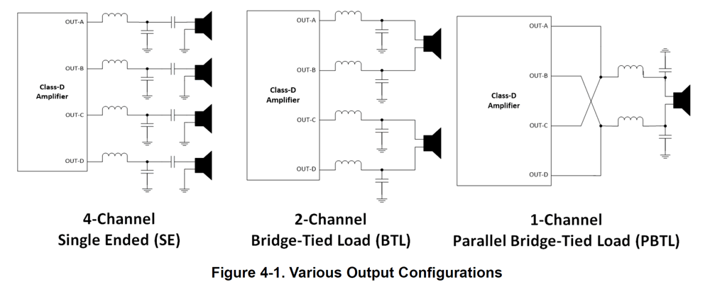
There's a lot going here, so fasten your mental seatbelts. First, I don't know of any unity-gain stable class-D power amplifier, so the 1k resistor was added the negative-feedback loop to attenuate the class-D amplifier's input signal, which the amplifier will then amplify back to unity-gain. Second, the black dots denote PCB edits, wherein the class-D amplifier's preexisting output shunting capacitor no longer terminates into ground but into the positive input terminal on the loudspeaker. Why the change? Having the two woofers shunted by this capacitor helps the woofers not see high-frequencies, thereby furthering the implicit low-pass filtering. (Yes, I know that if you haven't read my previous posts, this will make little sense. On the other hand, those in the know will let out a, "Well, duh.") One potential problem we face is that most class-D power-amplifier modules are now of the bridge-tied load (BTL) topology, not the "single-ended" (SE) topology I have shown here. The BTL type uses two class-D amplifiers in a balanced configuration with the load in between the two outputs. Image from Texas Instrument SLOA 290
Since monopolar power supplies are less of a hassle, class-D amplifiers are usually designed to operate with them, which means that their output sits at half the B+ voltage, which explains why the "single-ended" topology sports output coupling capacitors. In contrast, the BTL and PBTL topologies obviate the need for these huge coupling capacitors and improve the amplifier's PSRR, which is great, except that they don't work in my designs.
By the way, rather than further muddy the already muddy waters of audio nomenclature, the "single-ended" class-D topology should have been labeled LGT topology, which stands for Load Ground-Terminated. Or, we could have had GTL, Ground–Terminated Load—anything but "single-ended." Imagine the glee from the advertising department when they saw the label "single-ended" in the IC class-D data-sheet.
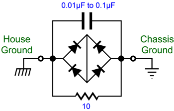
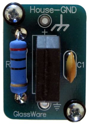
Free-Lunch Aikido Line-Stage Amplifier Sadly, the house-ground nightmare remains, but can be remedied with two House-Ground circuits, one per channel.
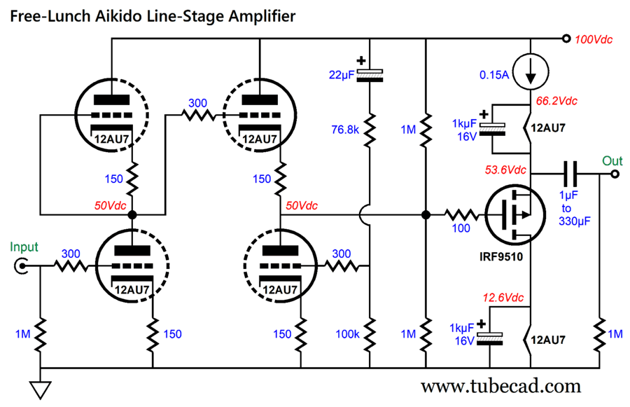
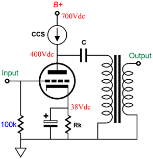
(Don't ask; I am sold out of the kits, alas.) In fact, I wonder if a dual-channel phono preamp could be built in two enclosures, with the turntable-ground going to the house ground. I also like to give the vacuum tubes DC-regulated heater power supplies. Why? No hum, longer life due to a slower turn on, that is if you design wisely. (A well-designed low voltage regulator will slowly ramp up to its target output voltage, which can be done with a large-valued capacitor across the voltage-setting resistor.) After several readers told me that separate heater power supplies for each channel sounded better, I decided to test this assertion. They were right, as a better sonic image resulted with greater clarity. Not a huge upgrade, but nonetheless a worthwhile one. Okay, how do we get all this and how do we do it effortlessly? Here is my hybrid solution, a power buffer also provides the heater current:
Note the single B+ voltage and no heater power supplies. What see here is a relatively low voltage Aikido gain stage followed by a MOSFET-based source follower, which is constant-current source loaded. This unity-gain follower idles at the required heater current (150mA), which is set by the constant-current source. The top 12AU7's heater element rides along with the output signal, thereby establishing a fixed voltage relationship between the top 12AU7's cathodes and their heater. The bottom 12AU7's heater sees a steady voltage drop due to the 1kµF shunting capacitor.
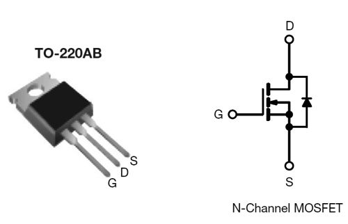
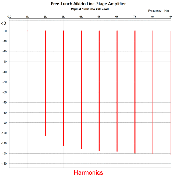
The P-channel MOSFET will get hot, as it dissipates 6.15W, so a heatsink will be needed for it. Although my assumption here is that each channel gets its own high-voltage power supply, a single power supply could be used. Note we cannot use different tubes in this configuration, as unlike the usual Aikido arrangement with its dedicated input and output tube, here the bottom triode holds an input tube and an output triode. The MOSFET can be replaced by an IRF9520 or something more modern. I would avoid replacing it with a PNP transistor, however, as the distortion went up in SPICE simulations. The MOSFET's idle current flow of 150mA is certainly hot for line-stage amplifier. On the other hand, the source-follower can burn through yards and yards of the most capacitance-laden interconnect. In addition, it shields the Aikido cathode follower output stage, which runs on woefully low idle current due to the very low B+ voltage, from tough external loads. Here is the SPICE-generated Fourier graph for 1Vpk at 1kHz into a 20k load resistance.
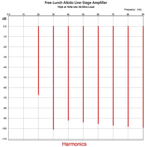
The MOSFET's idle current flow of 150mA makes it suitable for a single-ended headphone amplifier. Headphones from 32 ohms to 300 ohms could be easily driven to screaming SPLs. For example, 150mA into a 32-ohm load equals peak voltage swings of 4.8V, which is 4.8 times greater than your phone can deliver, and as voltage squared determines output power, it delivers 23 times more power. The peak output swing into 300-ohms headphones is staggering. With a 33 µF capacitor output coupling capacitor and 300-ohm load, the same SPICE simulation produces a nearly identical set of harmonics plotline as with the 20k load. Here is the graph for the circuit with a 470 µF capacitor coupling capacitor and 32-ohm load.
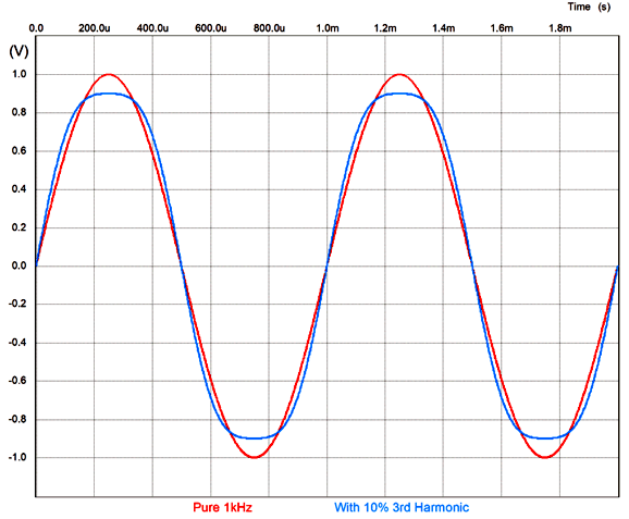
This is about as good as it gets. Why? Look at the 3rd harmonic. The third harmonic sounds like constrained, canned, fake, compressed music—because that is precisely what it is, i.e. compression.
Next, note the relatively strong 2nd harmonic, nature's harmonic and the single-ended signature harmonic. By the way, as each channel gets its own Free-Lunch Aikido, with separate grounds, balanced headphones would be the way to go. Failing that, the two grounds must be tied together at the ground terminal of the three-section headphone jack. The relatively high current and big potential voltage swings raises the possibility of a parafeed (i.e. parallel feed) power amplifier with a coupling capacitor and output transformer—a transformer without an airgap.
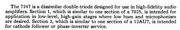
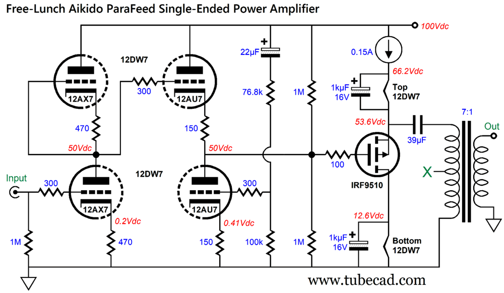
The first thing we do is replace the 12AU7s with 12DW7/ ECC832/7247 tubes, which are according to the tube manual:
The 7025 is the fancy version of the 12AX7. The input stage creates the needed gain, while the 12AU7-based Aikido cathode follower output stage delivers a low output impedance and enough current to drive the MOSFET's gate. For example, let's say that we wish to build a small single-ended amplifier to drive 4-ohm computer loudspeakers. The constant-current source displaces 33.8V at idle, which limits us to a potential output voltage swing of ± 30Vpk. We divide 30V by 0.15A to find the optimal load impedance and get 200 ohms. Next, we divide 200 by 4 and get 50, which we take the square-root of ( √ 50) to get the winding ratio, about 7 to 1.
By the way, we can also work out, on the back of an envelope, the maximum power output, by multiplying the idle current against the peak output voltage swing, 0.15A x 30V = 2.25W. This may not seem like a lot, but remember that the loudspeakers sit less than a yard from your ears. Besides, they sell $$$ 1W 300B-based OTL amplifiers, so you will have some bragging rights with your mighty two-watt single-ended amplifier. In addition, perhaps you have heard of a speaker company named Klipsch. For an 8-ohm loudspeaker, the winding ratio equals 5:1, while the primary impedance remains at 200 ohms. Where does one find an output transformer with a primary impedance of 200 ohms? How about a PA matching transformer. Here is Gemini to the rescue:
Parts Express sells a 15W constant-voltage audio transformer for $8.40, model 300-039; use the 5W primary tap. On the other hand, we could divide 115 by 7 and get 16.4. Why? We could find a 25VA 15Vac toroid power transformer, which might actually work better than the PA transformer. Wouldn't a 16Vac be better? Maybe. Maybe not, as the power transformer's output voltage is often quoted at peak power output with both the wire and core losses included. In other words, the 15Vac transformer might actually deliver 16.4Vac with an unloaded secondary. No doubt, some adventurous readers are thinking: why stop at a B+ voltage of only 100Vdc, why not use 300Vdc instead, so a 15W parafeed single-ended power amplifier could be made? Well, as I love to point out, topology is indifferent to scale.
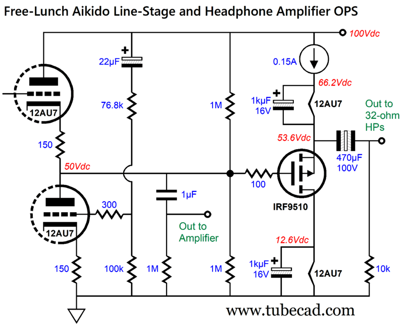
With a B+ voltage of 300Vdc, we could reasonably get 133V peak voltage swings, which against the 150mA idle current equals 10W of average (RMS) output power. Of course, a much bigger P-channel MOSFET will be needed (if not two in parallel), which will require running the Aikido cathode follower stage at a much higher idle current, say 10mA to cut through all the capacitance presented by the more powerful P-channel MOSFET. (An emitter-follower driver stage might be needed.) It's certainly doable, as we do not run into the usual limitation of maximum heater-to-cathode voltage limits. Or, we could build a dual-use Aikido, one that can drive either a power amplifier or 32-ohm headphones with it two outputs, giving us a pure-tube line-stage amplifier and a hybrid headphone amplifier.
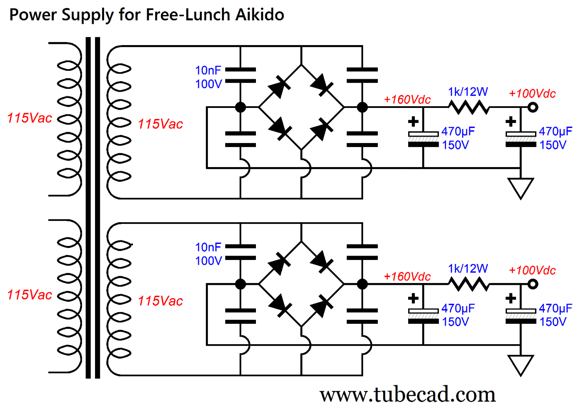
Of course, the 470µF output capacitor can be bypassed by a high-quality film capacitor. (Here the low-voltage B+ voltage works majorly in our favor, as nonpolarized electrolytic capacitors stop at about a 100V voltage rating and low-voltage polypropylene film capacitors are much cheaper than high-voltage ones. As for the power supply, here is one possibility.
I would use a 100VA toroid. The rectifiers can be HER108 or MUR420 or 600V FRED rectifiers; the latter are screaming fast, such as the VS-HFA04TB60-M3, which offers a reverse-recovery time of 28 nanoseconds. If we replace the RC filters with LC filter (choke and capacitor), the raw B+ voltage before the choke can be a low 105Vdc. Okay, if absolute dual-mono isn't your cup of tea, we can realize some big savings in cost and heat dissipation. Here is how:
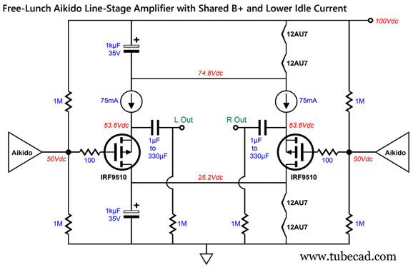
One power supply feeds it all—tubes, MOSFETs, constant-current sources, and heaters. Each P-channel MOSFET now draws half the idle current, only 75mA. The MOSFET dissipation drops to only 2.13W per channel, which translates to smaller heatsinks; in fact, we could probably get away with wimpy clip heatsinks. The 75mA constant-current source can be made from an LM317-HV and 16.5 current-setting resistor. In fact, a P-channel MOSFET and an LM317-HV can share the same heatsink. Moreover, if you are driving a stereo power amplifier, the dual mono construction offers little.
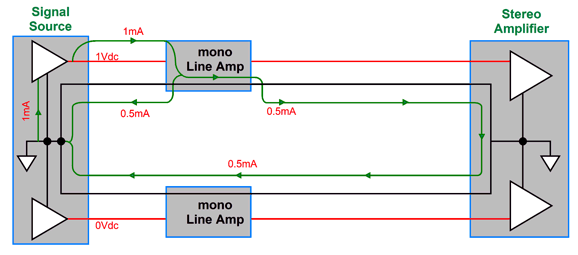
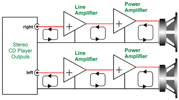
See my Post 537 for an explanation of what is going wrong here and what is going right below:
Note how the return current remain within their channels.
Music Recommendation: Agnes Obel, Aventine
Moreover, the album was curated by Agnes Obel, with one track of her music. Okay, that got my attention. Amazon Music streaming service offers a few of her albums in higher resolution than CD, which is welcome, as they are certainly audiophile grade.
//JRB
Did you enjoy my post? Do you want to see me make it to post 1,000? If so, think about supporting me at Patreon.
AI Summary Reasoning and Approach
User Guides for GlassWare Software
For those of you who still have old computers running Windows XP (32-bit) or any other Windows 32-bit OS, I have setup the download availability of my old old standards: Tube CAD, SE Amp CAD, and Audio Gadgets. The downloads are at the GlassWare-Yahoo store and the price is only $9.95 for each program. So many have asked that I had to do it. WARNING: THESE THREE PROGRAMS WILL NOT RUN UNDER VISTA 64-Bit or WINDOWS 7, 8, and 10 if the OS is not 32-bit or if it is a 64-bit OS. I do plan on remaking all of these programs into 64-bit versions, but it will be a huge ordeal, as programming requires vast chunks of noise-free time, something very rare with children running about. Ideally, I would love to come out with versions that run on iPads and Android-OS tablets.
|
I know that some readers wish to avoid Patreon, so here is a PayPal button instead. Thanks. John Broskie
John Gives
Special Thanks to the Special 89 To all my patrons, all 89 of them, thank you all again. I want to especially thank
I am truly stunned and appreciative of their support. In addition I want to thank the following patrons:
All of your support makes a big difference. I would love to arrive at the point where creating my posts was my top priority of the day, not something that I have to steal time from other obligations to do. The more support I get, the higher up these posts move up in deserving attention.
If you have been reading my posts, you know that my lifetime goal is reaching post number one thousand. I have 361 more to go. My second goal was to gather 1,000 patrons. Well, that no longer seems possible to me, so I will shoot for a mighty 100 instead. Thus, I have just 8 patrons to go. Help me get there. Thanks.
New URL of the GlassWare website |
||||


| www.tubecad.com Copyright © 1999-2026 GlassWare All Rights Reserved |