| John Broskie's Guide to Tube Circuit Analysis & Design |
| June 06 2026 | Post Number 640 |
||||
Extra Special
To Jean-Pierre Cloot
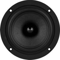
32-Ohm Speaker for OTL
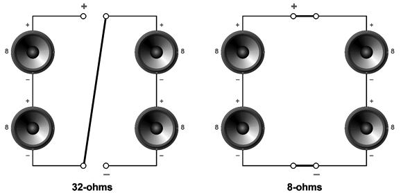
Assuming that all four drivers are fullrange drivers, all we need is a two-position toggle switch to make the transformation. On the other hand, if we add a tweeter, a very high SPL/W tweeter to the mix, things get a tad more complicated, but not insanely so.
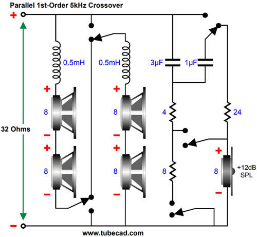
Resistance and inductance add in series, so the four 8-ohm woofers add up to 32 ohms, while the two 0.5mH inductors add up to 1mH. And with the twist of a six-pole, two-position rotary switch:
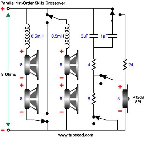
Now, the two capacitors add up to 4µF, while the two inductors, which are effectively in parallel, halve to 0.25mH. The tweeter now sees a -6dB padding attenuator, as the four series-parallel woofers deliver 6dB more SPL than when in series. On the other hand, we could design and build a 32-ohm loudspeaker for exclusive use with an OTL power amplifier. I like the idea of using four fullrange 8-ohm drivers, but only along with a single 8-ohm woofer.
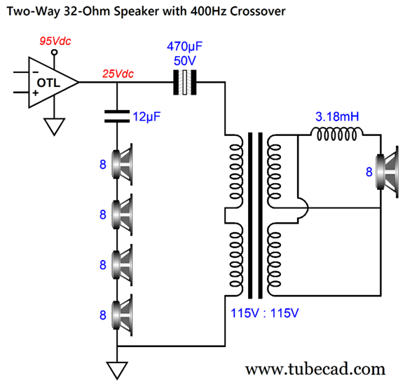
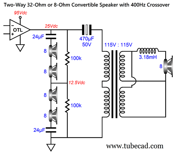
A 400Hz crossover frequency frees the fullrange drivers from the hard work of producing deep bass, and it allows us to use a narrow dipole panel to hold the four fullrange drivers. The transformer is merely an off-the-shelf toroidal power transformer with four 115Vac windings. By placing the primary windings in series and the secondary windings in parallel, we get a voltage ratio of 2:1 and an impedance ratio of 4:1, so the 8-ohm driver reflects as a 32-ohm impedance. I have measured quite a few toroidal power transformers, and just about all of them exhibited bandwidth out to at least 5kHz. Mind you, passing 20Hz is much harder than 50Hz or 60Hz. In other words, use a higher VA rated transformer than you might expect. For example, with a 25W OTL power amplifier, I would use a 100VA transformer. Note the wonderfully small-valued 12µF capacitor, which allows us to splurge on the high-price stuff. Had we used four woofers in series, the low-pass filter inductor would have to be four times larger in inductance. A higher impedance saves us in capacitor costs, but increases inductor costs. On the other hand, if we wish to retain impedance convertibility, we use the following crossover:
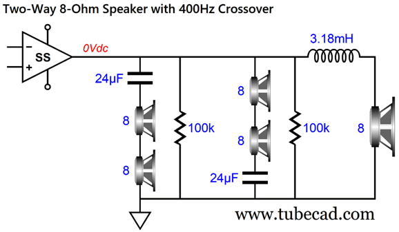
The two 24µF capacitors effectively become 12µF when in series. The two 100k resistors allow us to voltage-bias the crossover capacitors, which improves their sound. The four fullrange drivers see zero differential DC voltage across their voicecoils, so they are safe. To convert to 8-ohm impedance, we switch the parts around:
Yay!—we lost the toroidal transformer. Strictly speaking, the 100k resistors are not needed, but they also do little to hinder the operation of the loudspeaker. Here is what I would love to build:
The woofer is transmission-line loaded by the tapering length of exit port, which would be stuffed with polyfill or something fancier. Since the woofer sits so close to the floor, it gains a 6dB boost in SPL, which is a good thing, as most woofers offer a lower SPL per 1W than most fullrange drivers. (In addition, I assume that a subwoofer will be used and that these tall loudspeakers would see a 100Hz high-pass filter in front of the OTL power amplifier—or solid-state amplifier). Since I can leave any design alone for long, I altered the layout to increase standing stability and to bring the woofer in better time alignment with the fullrange drivers.
Feel free to imagine four spiked feet. (I once saw a French loudspeaker that held a single spike at the center of the bottom of the tall enclosure and four soft rubber feet at each corner. The idea was to make a mechanical analogy of a star ground. Interesting.) Speaking of imaginings, if I owned a table and radial-arm saw, I would be building loudspeakers all the time. Well, my loss is my neighbors gain, I suppose.
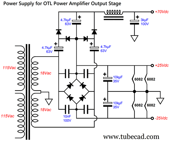
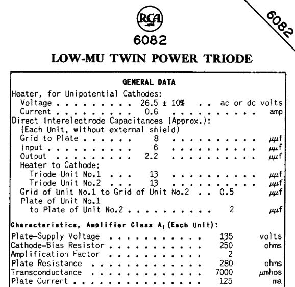
OTL for 32-Ohm Loads Let's do the math. To get 25W into an 8-ohm loudspeaker requires 20Vpk swings and 2.5A of peak current flow. To get 25W into a 32-ohm loudspeaker requires 40Vpk voltage swings and 1.25A of peak current flow. This is still a lot of current flow for an output tube, such as the 6AS7 (or its brothers, the 6080 and 6082). On the other hand, if we limit the 32-ohm load to only 20Vpk, the peak current demand falls to half, 625mA, and the wattage falls to 6.25W. Is this a tragedy? No, as four fullrange drivers present four times the radiating surface of a single fullrange driver, we gain 12dB in SPL. This puts us right back at the SPL that a single fullrange driver would produce with a 25W power amplifier (20Vpk into 8 ohms), but with the added advantage of much lower distortion, as the four fullrange drivers would remain within their sweet spot, having to move only one fourth as much. Of course, if we gave each of the four fullrange drivers 25W of power, 100W total, the OTL would need to swing 80Vpk and 2.5A peak into the combined 32-ohm load. Now, 2.5A peak current flow is what the 8-ohm load demands for 25W of power delivery. In other words, an OTL power amplifier that produced 25W into an 8-ohm loudspeaker could, with an increased power-supply voltage, deliver 100W into a 32-ohm load. In short, the closer the load impedance gets to the output tube's plate resistance, the more potential output power the OTL can realize. In other words, a 32-ohm load impedance is four times better than an 8-ohm load impedance. It's time to examine the plate curves of the 6AS7-type triode. "Type" because the 6080 and 6082 are the industrial versions of the 6AS7 twin triode. In fact, the 6082 is my choice for an OTL output stage, as it holds a 26.5V heater element, which only draws 600mA, not the 6AS7's 2.5A. It's a wash in terms of wattage expended heating the heater, but a huge improvement in rectifier loss with a DC heater power supply and makes heater regulation a possibility. In addition, we can place many 6082 heaters in series across the B+ voltage and ground. Here is an example:
Note that this is just one possible power supply and that four 6082 tubes are used. If you spotted that that the heaters only see 25Vdc, not 26.5V, you are observant. I like to power tubes with slightly less heater voltage, as it extends their lifespan, using 6V for 6.3V tubes and 12V for 12.6V tubes.
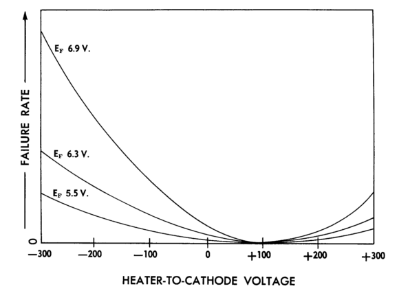
Note that the increased heater voltage leads to increased failures. (One California pro-audio electronics company ran all their 6.3V tubes on regulated 5Vdc power supplies; the owner told me that they never experienced a tube failure or even a worn-out tube.) Here is some more 6082 data:
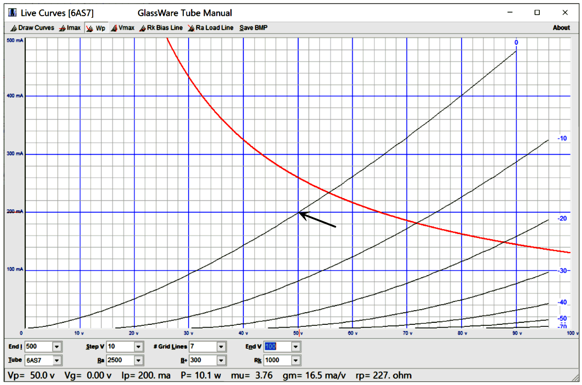
Note that the amplifier factor (mu), plate resistance (rp), and transconductance (gm) are identical to the 6AS7. Well, now it's actually time to examine the plate curves of the 6AS7-type triode.
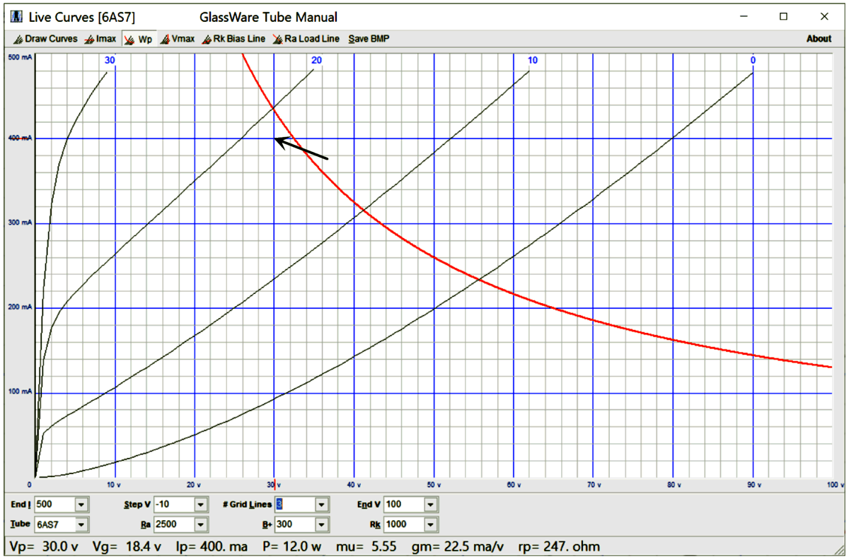
With a cathode-to-plate voltage of only 50V, the triode dissipation is 10W and the cathode current flow is 200mA. The triode has a 13W maximum dissipation limit, so 10W is a safe limit to abide by. Note that the grid voltage is zero. In other words, the grid is at the same voltage potential as its cathode. This marks the limit to easy and simple OTL design, as once the grid exceeds the cathode voltage, the grid goes from being an extremely high load impedance to transforming into a diode that conducts current and whose input resistance fall drastically, making huge demands on the driver stage and making capacitor coupling to the grid difficult. This location on the triode's plate curves is worth memorizing. For example, if you wish to build an OTL push-pull headphone amplifier that delivers 200mA of output current, then you only need to add the peak voltage drop across the headphone voicecoil to the 50V to get the required ±Voltage for the bipolar power supply. For example, if the headphone impedance is 50 ohms, 200mA will produce a peak voltage drop of 0.2A x 50 ohms which equals 10V, so the bipolar power supply must be at least ±60Vdc. Only one 6AS7 per channel is needed. If the headphone impedance is 16 ohms, ±53.2Vdc would be needed. On the other hand, if we need to deliver 400mA peak into a 50-ohm driver, two 6AS7 tubes will be needed with the ±60Vdc bipolar power supply, 120Vdc with a monopolar power supply. Bear in mind that many OTL-power-amplifier designers simply ignore the maximum wattage dissipation limit, working under the assumption that music, not steady test tones will be amplified, so an occasional entry into positive-grid current is acceptable. For example, one 6AS7 triode can deliver current peaks of 400mA, but it will require a cathode-to-plate voltage of at least 80V. (Note where the 0V grid-voltage line intersects the 400mA horizontal line.) Or, if we are willing to deal with positive-grid current, we could use a much lower power-supply voltage; for example, ±50Vdc with a 200-ohm load, as the load would experience a 20V voltage drop, leaving a cathode-to-plate voltage of 30V.
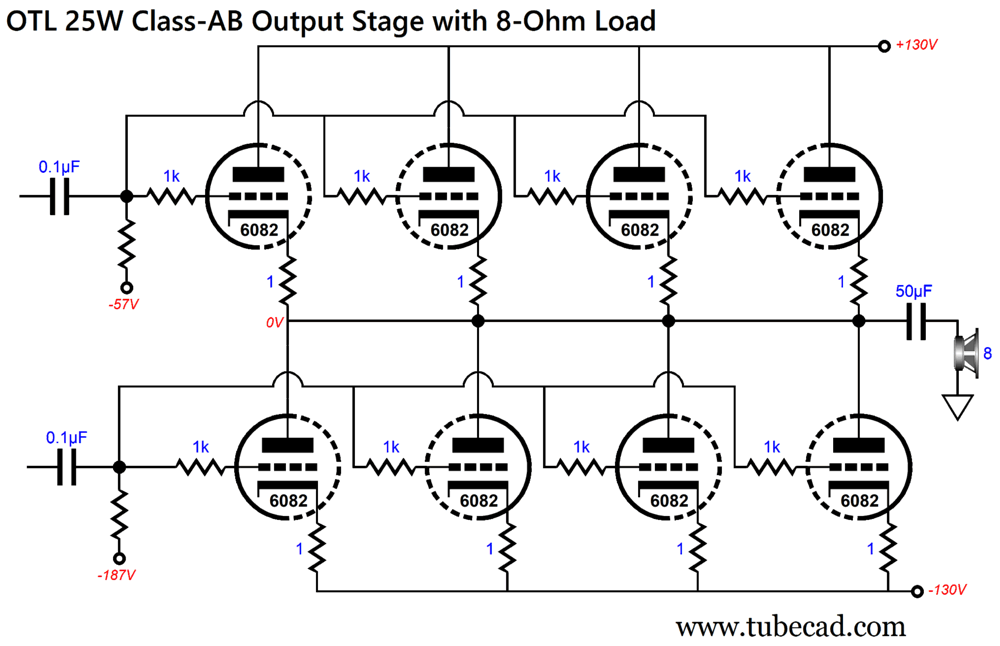
Ideally, we desire as low a bipolar power supply voltage as possible, which ±50Vdc certainly qualifies as. Why? Not only can we get away with lower-voltage power-supply parts, such as reservoir capacitors, but the tubes can idle at a higher current without suffering the penalty of excessive dissipation. Say, we limit ourselves to a plate dissipation of 5W per output triode at idle. With a 50V voltage drop, the triodes can idle at 0.1A each; in contrast, with a ±130Vdc bipolar power supply, only 38mA. Mind you, high power-supply voltages lead to tube failures. Nonetheless, with a ±130Vdc bipolar power supply, we can get 25W (20Vpk and 2.5A peak) into an 8-ohm load.
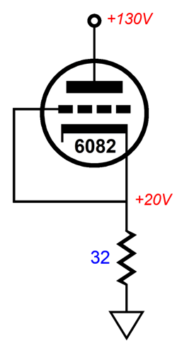
The 50µF output coupling capacitor imposes a 400Hz 1st-order high-pass filter on the 8-ohm driver. This is an echo of the loudspeaker design in the previous section. Yes, we are thinking bi-amplifiers here. Each triode gets its own 1-ohm cathode resistor to prevent current hogging. The way we know that this would work is that a single 6AS7 triode, with a 32-ohm cathode resistor and B+ voltage of 130Vdc and cathode-to-grid voltage of 0V, will see a 20V cathode voltage. And as the four triodes are in parallel, we get 20V with an 8-ohm load.
This is the quick test to see if the OTL design is going to work (without entering positive-grid current). We can use this same test rig to find what B+ voltage is needed to develop a 20V voltage drop across a 64-ohm cathode resistor. Why 64 ohms? It is what two 6AS7 triodes would see as the load impedance with a 32-ohm loudspeaker.
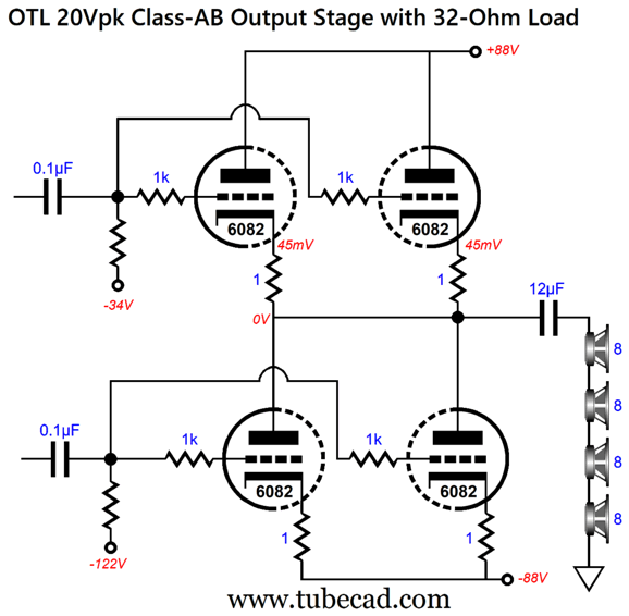
A rail voltage of 88V is not too bad. Here is the output stage:
Both of these OTL output stages with their specified load impedance will produce the same maximum SPL, but the 32-ohm load will effectively see a higher damping factor, in spite of the higher output impedance from half the output tubes. Tubes only get more expensive over time, so it behooves us to use as few as possible. Only two tubes per channel are quite frugal. In addition, the 12µF also constitutes a savings. By the way, some readers will have spotted that 12 is not exactly one quarter of 50. True, but we must include the higher output impedance in the equations, which the 12µF coupling capacitor factors in the mix. Okay, can we get anymore tube-frugal? I don't see how, while remaining pure-tube. I do, however, see a way to achieve class-A, push-pull output, albeit in a hybrid fashion.
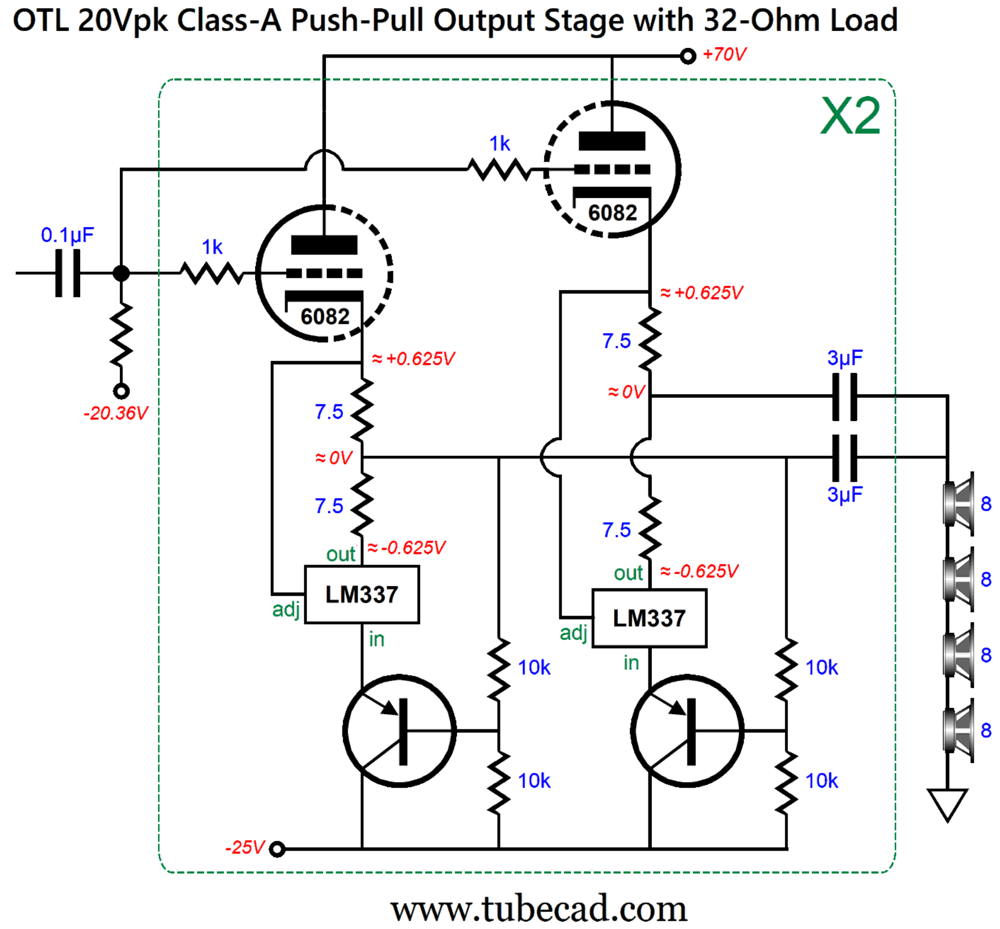
Somersault OTL for 32 Ohms
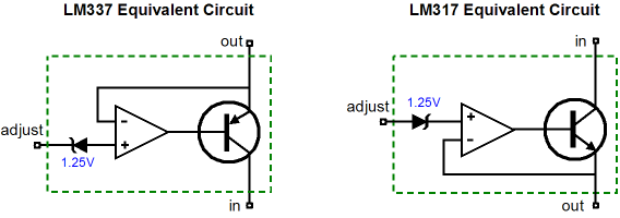
Since these regulator max out at 37V, we must cascode them with a power PNP transistor, such as the D45H or TIP32AG or MJE15033. Each of the four output triodes gets its own LM337-combo, so as to independently auto-bias each triode. The four 3µF output coupling capacitors are effectively in parallel, so their combined capacitance equals 12µF. I labeled this topology the "Somersault OTL" decades ago when I detailed the impedance-multiplier circuit (IMC). A more detailed explanation is given in my Post 281, where I show a 300B-based version. Think of it as a hybrid upside-down version of the SRPP topology. The LM337 regulator holds an internal 1.25V voltage reference, which explains why the 7.5-ohm resistors are used, as 1.25V divided by 15 ohms sets the idle current.
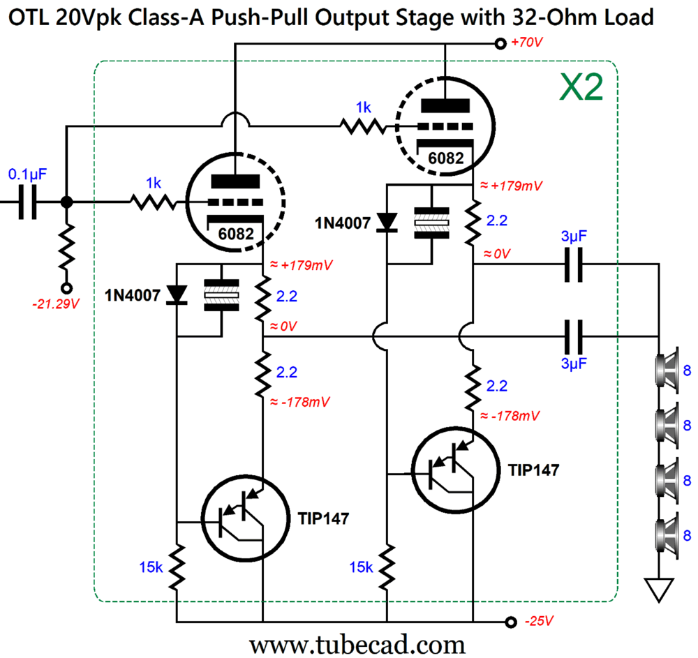
On the other hand, we can roll our own negative half of the push-pull class-A output stage, using a Darlington PNP transistor, such as the TIP147.
The TIP147 transistors' base voltages are not displayed, but they are at -0.42V, which explains how we can use the voltage drop across a single 1N4007 rectifier as the voltage reference. If we used a monopolar power supply, then the TIP147's tab need not be electrically isolated from its heatsink, as it will be at ground potential. (It only dissipates 2W, so a small clip-on heatsink can be used on each TIP147.) I ran this circuit in SPICE simulations with a tube-based input stage. I expected to see typical push-pull harmonic structure. I didn't.
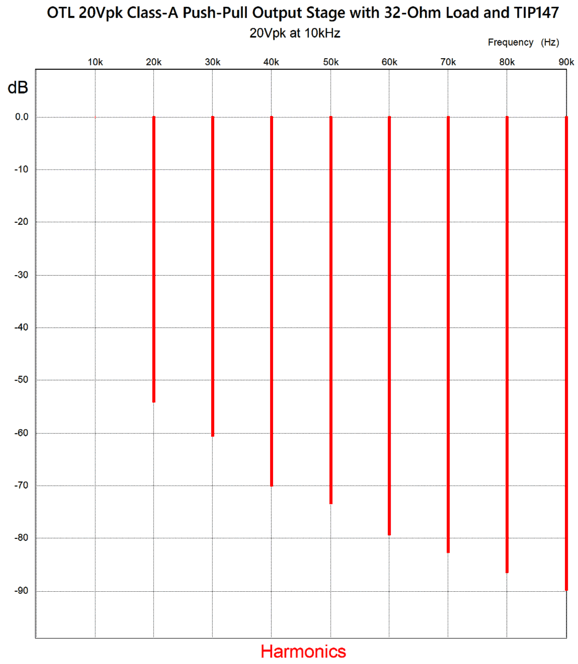
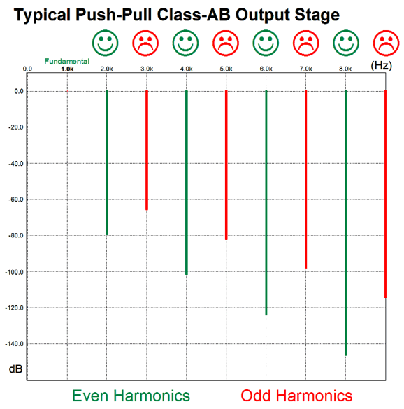
Bear in mind that this is at full output, 20Vpk, and with a 10kHz input signal. Looks dang single-ended to me. Single-ended! How did this happen? The output stage does run in class-A, but that is not enough to explain the total expurgation of the typical push-pull harmonic structure.
Part of the answer must be that this Somersault topology is actually a lazy push-pull topology, as the bottom output devices, be they LM337s or TIP147s, are controlled by the top output devices, not by a phase splitter and driver circuit. In other words, the bottom devices only mirror and invert the top devices, which in this design are triodes.
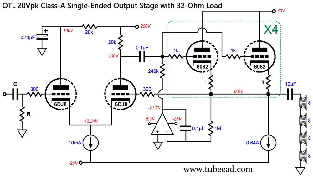
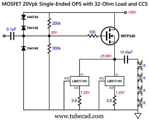
Single-Ended OTL
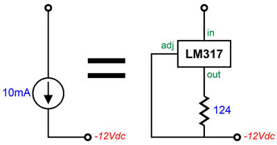
No savings in output tubes, but neither is there an increased cost of more tubes. The driver stage consists of a cathode-coupled amplifier that uses its inverting input to create a negative-feedback loop to the output. In other words, the 6DJ8 is in control of the 6082 enslaved output tubes. This results in less distortion and lower output impedance. The 1-ohm cathode resistors help to prevent current hogging by any triode(s). The cathode-coupled amplifier's 10mA constant-current source could be made from a single LM317-HV IC regulator and resistor.
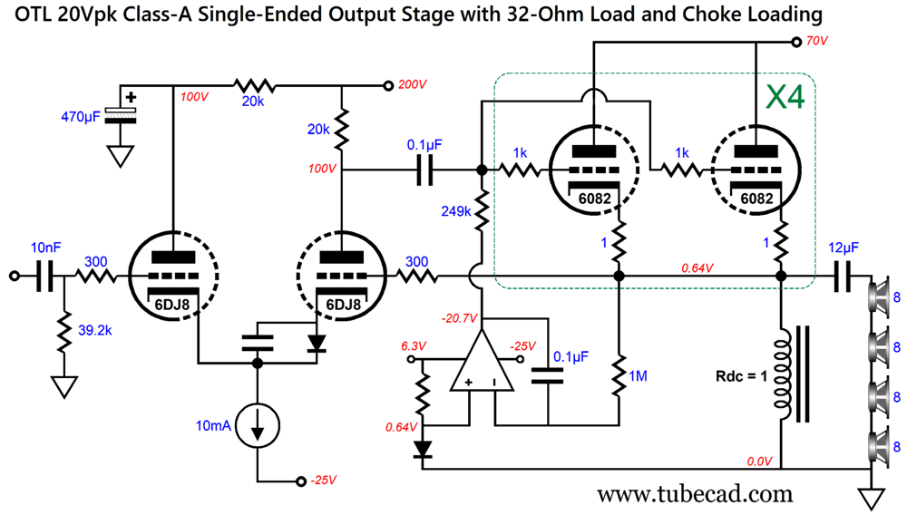
The input capacitor C and resistor R can either deliver near infinite bandwidth (by using high part values) to the output stage or impose a high-pass filter. For example, a 400Hz high-pass filter would combine with the output coupling capacitor to create a Linkwitz-Riley 2nd-order high-pass filter. With eight parallel triodes, each drawing 80mA at idle and each drawing 158mA at 20V of peak output voltage swing, the output stage remains within the class-A envelope of operation with constant-current source loading. A single-ended output stage with constant-current source loading is only theoretically 25% efficient. Of course, with vacuum tubes this percentage is laughably off. If nothing else, the heater dissipation is 128W and the triodes and constant-current source dissipate 78W at idle. Add the two wattages together and we get an efficiency of 10% at best. If a single-ended output stage is inductor loaded, however, the theoretical efficiency climbs to 50% efficient.
At idle and at full output, the inductor dissipation is a mere 0.4W. In addition, the inductor's DC resistance (DCR) is used to auto-bias the output tubes. The cathode-coupled amplifier gets the extra diode and small bypass capacitor to offset the DC offset at the top of the inductor. (Of course, a 127-ohm resistor could be used instead.) The 10nF capacitor and 39.2k resistor impose the 400Hz high-pass filter action upon the output stage. By the way, not only are 32-ohm loads easier on triodes, but a single MOSFET would prefer it as well.
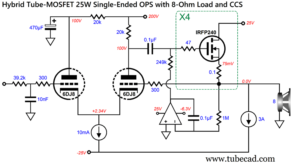
Those who devoutly follow the strictures of the cult of the Pure-Tube will balk at my having tossed a turd into the punch bowl. But as I belong to no church, and as my aim here in the Tube CAD Journal is to expand the world of audio topologies, not reduce it, this design offers a nice reality-check. I would love to build both designs, and then hold a shootout. (My money is on the tube version, but who knows which triumphs.) In fact, we could use the same topology for 8-ohm loads.
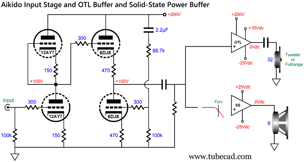
Once again, the 6DJ8 is in control of the four output MOSFETs. The low-pass filter uses the same part values as the high-pass filter, but with flipped positions. No output coupling capacitor or output transformer is needed, as the DC servo keeps the output offset free; and, unlike the triode output stage, the MOSFETs do not need to warm up before conducting. Since none of these designs offer any signal gain, where will the gain come from? Here is one possibility.
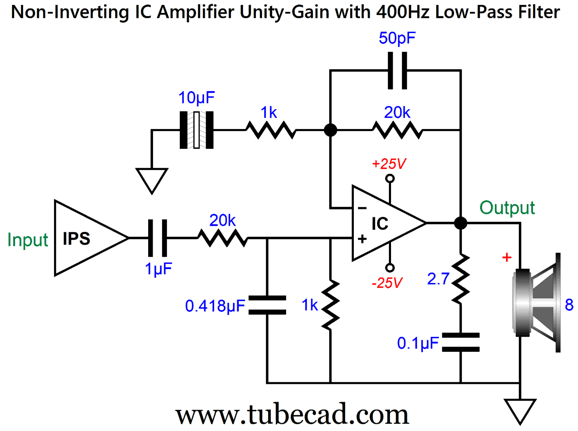
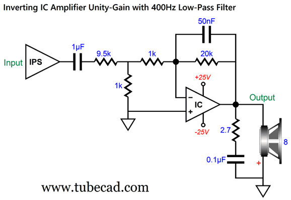
The 12AY7 is a fun twin triode tube that offers a mu of 40, so the Aikido input stage yields a gain close to 1:20 or 26dB. If less gain is needed, a 6DJ8 can replace the 12AY7; if more gain, a 12AT7, 5751, or 12AX7. Since the fullrange drivers only operate above 400Hz, do we really need a single-ended amplifier to drive the 8-ohm woofer? Of course, some would argue that 20Hz to 400Hz is the most critical portion of the audio bandwidth. Maybe, but that is not what I hear when listening to just that restricted bandwidth. In other words, why not use a chip-amplifier, i.e. an IC power amplifier, such as the LM3886? Hell, why not a class-D amplifier? One problem is that few solid-state amplifier are unity-gain stable. One workaround is to throw away signal gain before the amplifier adds it back.
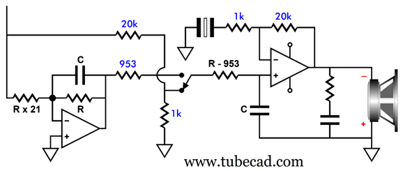
IPS stands for input stage, which we assume is a truly fine tube-based one. The 20k resistor in series along with the 1k resistor to ground form a two-resistor voltage divider, which throws away 95% of the signal from the input stage. The IC-based power amplifier then supplies a gain of 1:21, returning us to unity-gain. The 0.418µF capacitor creates a 400Hz low-pass filter. The rest is just standard solid-state amplifier furniture. There is a saying in electronics, "whenever possible, invert." Why? It prevents potential positive feedback, as the output is inverted, so it can only subtract, not multiply. In addition, an inverted amplifier does not create as much input stage distortion. I asked the Gemini AI to back me up. Here is what it said:
As they say, an expert is someone who agrees with you. Well, the expert has spoken. Here is the inverted version:
Note the reversed phasing on the woofer. This circuit also tosses gain out the window before amplifying it back.
If I didn't weary of sitting and typing, I could go for ever. Yes, damn it, forever. Okay, almost forever, but "forever" is still directionally correct. Thus, let's pull back and take an aerial view. Four high-quality fullrange drivers can deliver wonderful sound, especially with a dipole enclosure (i.e. no enclosed rear radiation), so, too, can an 8-inch woofer, especially with transmission-line loading, as can a tube-based OTL amplifier, especially a single-ended one with a relatively light load of 32 ohms. Add the three together and you might have a better loudspeaker than can be bought. If nothing else, it wouldn't cost $250,000.
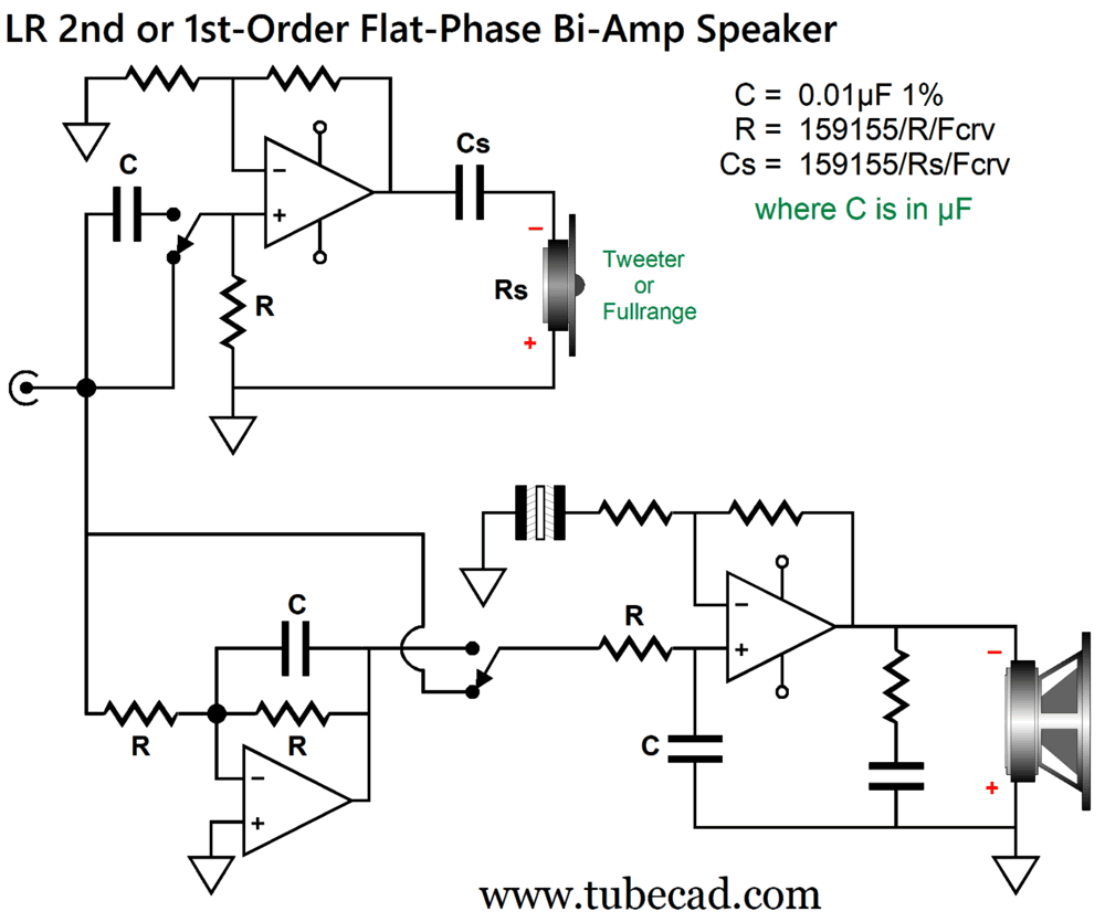
Switchable-Slope Crossover
Why? Let's say you are listening at low volume levels or at higher SPLs, but with polite classical or folk or jazz music, then choose the 1st-order crossover (the switch position shown above) that delivers better imaging and transients. On the other hand, when it's time to anger you loved ones and neighbors, switch to the loudspeaker 2nd-order slopes, (the other switch position) as it will further unload the fullrange drivers.
Mind you, the OTL amplifier isn't likely to ever damage the four fullrange driver in series, but not having to produce as much deep bass does help improve midrange clarity. With a 400Hz crossover frequency, the 1st-order filter will be -20dB down at 40Hz (1/10th), while the LR 2nd-order's steeper slopes will be down -40dB (1/100). On the other hand, if you are bi-ampping a two-way speaker with a 1-inch tweeter and using a powerful tweeter amplifier, the 2nd-order's steeper slopes are far safer. The low-pass filter based on the inverting amplifier can also apply a deep pre-attenuation of the signal for the solid-state amplifier that drives the woofer.
The inverting low-pass filter also attenuates the input signal, as does the two-resistor voltage divider, both equally so. And both deliver the same output impedance (assuming no output impedance from the inverting amplifier). Thus, in both toggle-switch positions, the output impedance presented is 953 ohms, which we factor into the RC filter's resistor. If the inverting amplifier's output impedance is 43 ohms, we replace the 953-ohm resistor with a 910-ohms resistor. (I wasn't thinking of tubes and OTL amplifiers when I devised this arrangement, just OpAmps and solid-state amplifiers.)
I recently discovered a new blues artist and rediscovered an old one. I own one Otis Taylor album, Fantasizing About Being Black. The title requires some explanation. Although a black gentleman, Taylor's eyes are pale blue, which explains why his first album was titled Blue-Eyed Monster. (Also noteworthy about his eyes is that he seldom blinks.) It turns out that we are neighbors of sort, as he lives, and has lived for decades, in Boulder Colorado, about 50 miles south of me, and where I have driven to far too often. What makes his blues extra interesting is that he plays guitar, very well indeed, but also banjo, which few would consider a blues instrument. Taylor disagrees, he points out that the banjo has a long blues history.
His album, White African, got my attention when the track, "Resurrection Blues," played in the background in a YouTube video I had watched. Add it to your list of audiophile demo tracks. I liked the album so much that I listened to Taylor most recent album, Otis Taylor Live. Very good, as well. Lots of fun, in fact. Yes live albums are seldom great sonic wonders, but they often deliver an emotional connection missing from sterile studio recordings.
The new bluesman was Pete Alderton. I do not remember hearing of him. Born of an American father and British mother in England, he lives in Germany. A few times he sounds American; at most others, English, but always very American blues influenced. Amazon Music streaming service offered two higher-resolution albums, both of which I enjoyed. Definitely worth checking out.
//JRB
Did you enjoy my post? Do you want to see me make it to post 1,000? If so, think about supporting me at Patreon.
AI Summary This document discusses designing convertible-impedance loudspeakers and optimizing OTL tube amplifier performance for different speaker loads. Convertible-Impedance Loudspeakers for Versatile Amplifiers This article discusses designing loudspeakers with switchable impedance for compatibility with both OTL and solid-state amplifiers.
Advantages of 32-Ohm Loads for OTL Amplifiers Switching to 32-ohm loudspeakers benefits OTL amplifier performance by reducing current demands.
Tube and Solid-State Amplifier Design Strategies The article explores various tube-based and hybrid amplifier topologies optimized for 32-ohm loads, emphasizing efficiency, low distortion, and simplicity.
User Guides for GlassWare Software
For those of you who still have old computers running Windows XP (32-bit) or any other Windows 32-bit OS, I have setup the download availability of my old old standards: Tube CAD, SE Amp CAD, and Audio Gadgets. The downloads are at the GlassWare-Yahoo store and the price is only $9.95 for each program. So many have asked that I had to do it. WARNING: THESE THREE PROGRAMS WILL NOT RUN UNDER VISTA 64-Bit or WINDOWS 7, 8, and 10 if the OS is not 32-bit or if it is a 64-bit OS. I do plan on remaking all of these programs into 64-bit versions, but it will be a huge ordeal, as programming requires vast chunks of noise-free time, something very rare with children running about. Ideally, I would love to come out with versions that run on iPads and Android-OS tablets.
|
I know that some readers wish to avoid Patreon, so here is a PayPal button instead. Thanks. John Broskie
John Gives
Special Thanks to the Special 89 To all my patrons, all 92 of them, thank you all again. I want to especially thank
I am truly stunned and appreciative of their support. In addition I want to thank the following patrons:
All of your support makes a big difference. I would love to arrive at the point where creating my posts was my top priority of the day, not something that I have to steal time from other obligations to do. The more support I get, the higher up these posts move up in deserving attention.
If you have been reading my posts, you know that my lifetime goal is reaching post number one thousand. I have 361 more to go. My second goal was to gather 1,000 patrons. Well, that no longer seems possible to me, so I will shoot for a mighty 100 instead. Thus, I have just 8 patrons to go. Help me get there. Thanks.
New URL of the GlassWare website |
||||


| www.tubecad.com Copyright © 1999-2026 GlassWare All Rights Reserved |