| John Broskie's Guide to Tube Circuit Analysis & Design |
| March 31 2026 | Post Number 636 |
||||||||||||||
Special Thanks to
Active-Augmented Crossovers
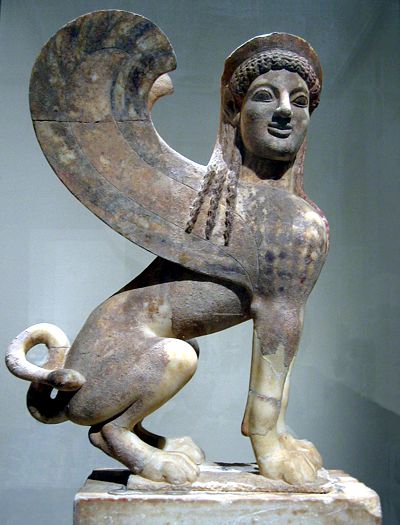
Not the Ancient Egyptian Sphinx with a lion's body with a man's head, nor was it the Ancient Greek Sphinx with a lion's body and a woman's head, along with wings—the one who posed a question.
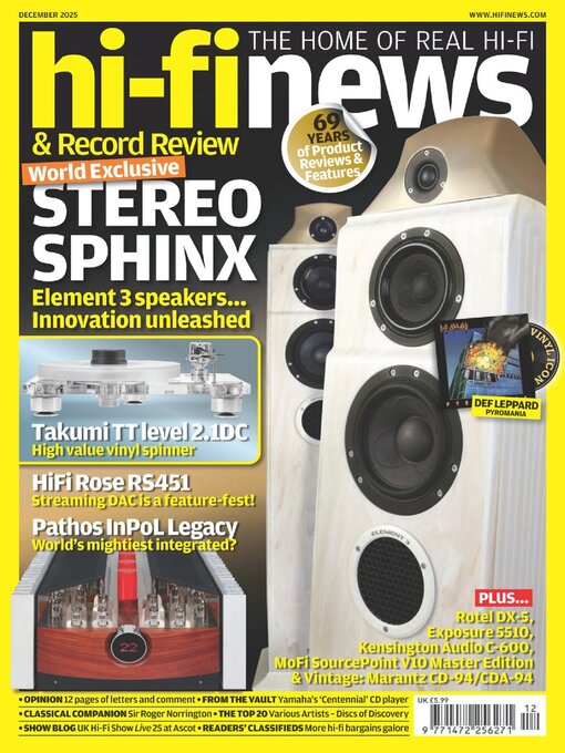
Actually, the Greek hybrid beast asked a riddle, now famous: "which is the creature that has one voice, but has four feet in the morning, two feet in the afternoon, and three feet at night?" If you didn't deliver the right answer, she got a free lunch. Oedipus, being a clever chap, escaped being eaten by giving the right answer: "A man, who crawls on all fours as a baby, walks on two as an adult, and needs a walking cane when old." No, it was a still different Sphinx altogether, but one that nonetheless instantly prompted a big question in my mind—a riddle was more like it. It all started when I read a review of the new Sphinx loudspeaker in the British audio magazine, Hi-Fi News, the December 2025 issue, which I only read this month. (I seldom read audio-gear reviews. Why not? Rarely, so very rarely, do I find them truly informative. Indeed, often the reviews remind me of women's romance novels, dripping as they are with much emoting and florid adjectives, along with that same deep dive into interiority, the exploration of the review's feelings and audio longings. And much like a romance novel, the ending always ends happily. How I long for the old Audio magazine's inclusions of an occasional schematic within the review, something solid to bite our mental teeth into.)
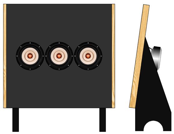
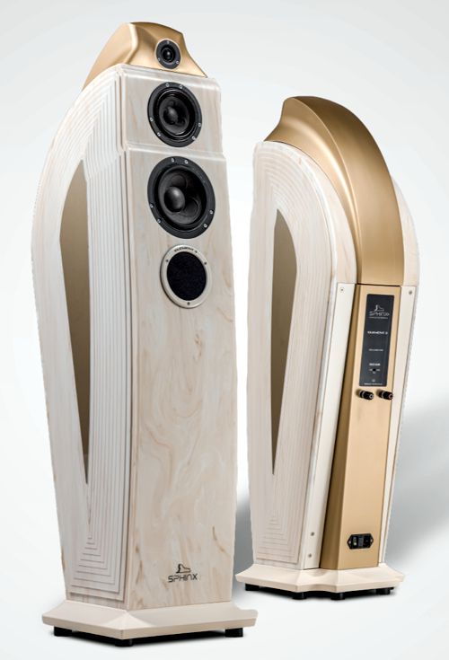
That's it on the cover, the Sphinx Element 3, which certainly presents a bold appearance for a loudspeaker, along with a matching bold price-tag of $47,500 for the pair of these Dutch loudspeakers. Okay, I know that some readers are thinking, "Yeah, it's an arresting-looking loudspeaker, but $47,500 is hardly newsworthy; in fact, in today's high-end scene it is, although not quite beer-budget or entry-level, still sort of middling in price, as it would need an extra zero to get my attention." I understand this take, as there are plenty of expensive high-end loudspeakers, but how many have the following set of specifications? From the Sphinx Audio website: A 3-way loudspeaker built for effortless detail,
Note the impedance of 16 ohms; next, behold the SPL of 94dB at 2.83V. The woofer and midrange driver appear to be from the Scan-Speak Illuminator series, which does not make any 16-ohm drivers, and their 8-ohm drivers do not deliver 94dB, as far as I know. Then, there's the PAC ™ crossover, which seems to stand for passive-active crossover, which would help explain why the loudspeaker sports an AC-power input socket on the rear panel. From its brochure, "This 3-way system is phase perfect." More from the website:
From the Hi-Fi News' review, we learn:
Okay, this is definitely not your father's loudspeaker crossover; hence the riddle I had to answer: how does it work?
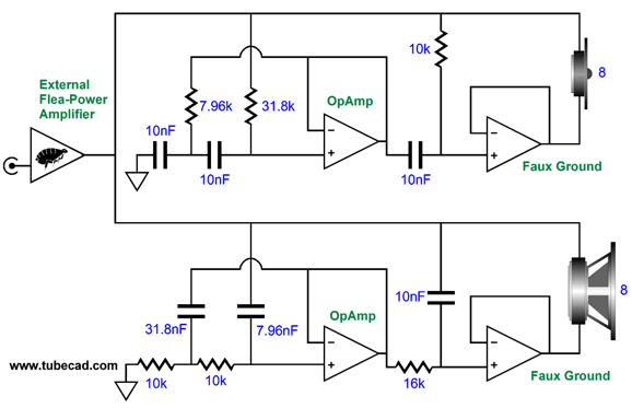
But first, I will disclose one of my absolute best stories, dang close to tombstone worthy. Back in the 1990s, my date and I were in a comedy club in Silicon Valley (Sunnyvale, I believe). We sat at a table with another couple, with whom we chatted before the show began. The fellow told me, in a super animated fashion, that he had designed for his company an amazing variable high-voltage regulator that delivered up to 2600Vdc in 40mV increments. The show started, I got to work, drawing out a schematic on the back of the show's flyer. At the show's end, I showed him the schematic. He flipped out, exclaiming, "What are you, man, some f*cking industrial spy?" "No, nothing like that," I responded, "just a guy with an interest in high-voltage regulation. Besides, if I were an industrial spy, would I show you the schematic?" "Man, that's my design. F*ck man, you not only have my circuit, but you even listed the part values and names of the brands I used. How could you know all that if you aren't a spy?" "To be honest, it's all pretty obvious. I divided 2600 by 0.04 and roughly got 2 to the 16th power, which meant that you were using a 16-bit DAC to create the voltage increments; and there's only one DAC with tight enough linearity to make your spec. And the floating low-voltage power supply that powers the OpAmp is something I play with all the time, so I know all about protecting the inputs from the high-voltage lag time on the RC filter. And the Vishay bulk-foil S104 0.01% resistors have a 1W power rating and voltage limit of 350V, so I knew you would have to place many in series…" "Wait a minute. It took me four months to design, build, and test it. You expect me to believe that you just doodled it in an hour while laughing?" "Well, as I said it was all fairly obvious. You know, things like the optical data feed for the DAC and the cascoded high-voltage 1kV MOSFETs..." "Okay, let's say I believe you, what do you do?" "Oh, I design power amplifiers, mostly tube-based, but not for a living, just for fun." What I didn't have time to tell him was that I was in a fierce competition with my brilliant friend, Steve Macuch, who was equally obsessed with high-voltage regulators as I was. As a result of our rivalry, I designed several new high-voltage regulator topologies every week, one of which was a lower-voltage version of what I had just drawn, which used an 8-bit DAC and offered 2V voltage increments. In other words, I just had to remember my own design and upscale it to accommodate the increased voltage. Okay, we return to the Sphinx Element 3 active-passive crossover. The riddle presented was not altogether new to me, as I have been obsessed with active-passive crossovers for almost half a century now. So, much of what I read had the quality of déjà vu, as some of my ideas, such as the impedance-multiplier circuit (IMC) and the inverted active filter that treats ground as the signal source and the input signal as the ground, instantly came to mind. A good example can be found in my Post 552, where we see the following design:
This is a 3rd-order Butterworth two-way active crossover that forgoes big, expensive, poor-tolerance speaker passive crossover parts for small, cheap, high tolerance parts. Unity-gain power buffers act as "faux" ground connections. This arrangement yields the same SPL and load impedance as a passive crossover would. In other words, it fails to deliver the 16-ohm impedance and higher SPL of the Sphinx Element 3. Post 552, however, also includes this enhancement:
Here we see the same crossover but with 6dB of gain and yet an 8-ohm load impedance for the external power amplifier. From Post 552:
If the inverting amplifiers gain is increased to 1:3, we get 12dB more SPL, but the load impedance would fall to 2 ohms without the IMC. With the IMC, we could get a 16-ohm load impedance along with the 12dB of gain. "To be honest, it's all pretty obvious."
In memory of the late Harvey "Gizmo" Rosenberg, now it is time to take some baby steps. Just a few weeks before his death, Dr. Gizmo told me to print a banner with the emblazoned phrase, "BABY STEPS," and to place it above my computer monitor, so I could be reminded of its wisdom as I typed.
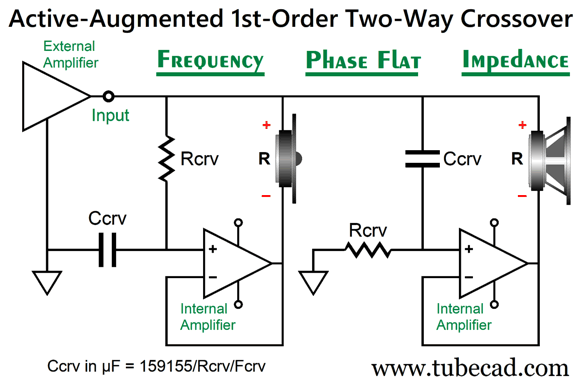
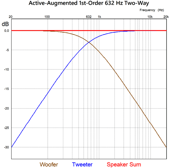
Active-Augmented 1st-Order Two-Way Crossover
On the other hand, if we are crossing over from a woofer to a fullrange driver, with a low crossover frequency, say between 200Hz to 500Hz, then the issues of lobbing and too little protection are lessened—but at the cost of big-valued capacitors and inductors. A crossover frequency of 200Hz requires a 100µF crossover capacitor for the fullrange and a 6.4mH inductor for the woofer, assuming 8-ohm drivers; thus, the appeal of an active-augmented crossover, as an active 200Hz crossover only needs two 0.1µF capacitors and two 8k resistors.
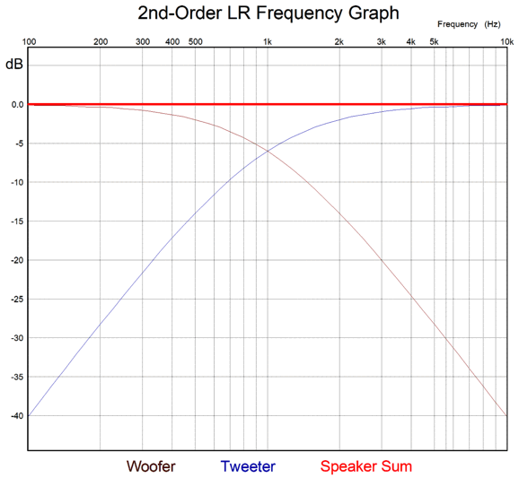
The 1st-order crossover delivers -20dB of attenuation per decade of frequency from the crossover frequency. For example, with a crossover frequency of 4kHz, the tweeter will see a -20dB decrease in signal strength at 400Hz, which equals 1/10th as much voltage as the woofer sees at 400Hz. Let's use a crossover frequency of 632Hz, as it is the geometric mean frequency between 20Hz and 20kHz, as 632/20 = 20,000/632, which will center our 20-to-20k graph.
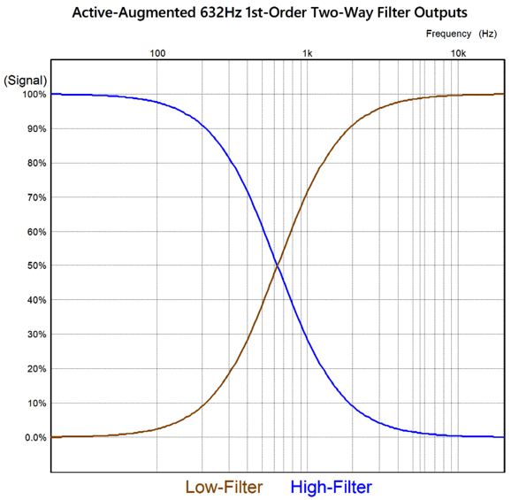
Here we see the signal strengths that the woofer and tweeter see across their terminals. But the signal the power unity-gain buffers put out looks much different:
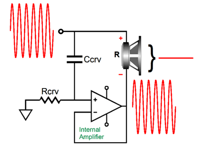
Yes, the tweeter buffer delivers 100% of the deep-bass signal, while the woofer buffer relays 100% of the ultra-high frequencies. (Just the opposite of what you would expect.) The buffers go from no output to 100% output, as in this active-augmented arrangement the way to reduce the signal across a loudspeaker driver is by exploiting the speaker's intrinsic differential nature, i.e. a speaker voicecoil only responds to voltage differences across its terminals. If we apply 100Vdc to both terminals, no puff of smoke appears, no movement occurs, as no differential voltage exists. Therefore, if we want a woofer to ignore a 20kHz input signal, we could apply the same 20kHz signal to both its terminals.
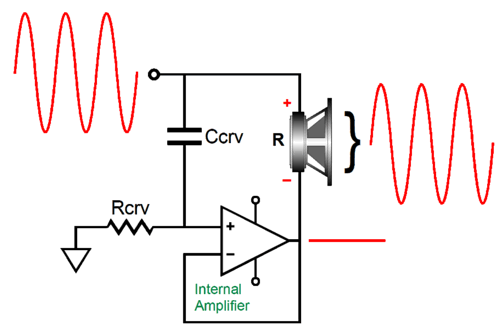
As far as the woofer is concerned, there is no input signal, as there's no voltage difference between its two terminals. In contrast, if we want a woofer to respond to a 100Hz input signal, we need to create a voltage difference.
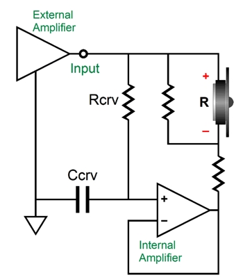
The simple RC filter delivered these results, as the capacitor could pass along the high-frequency signal, but not the low-frequency signal. What we have is something like using the ground as the signal source for a low-pass filter. With the tweeter, we simply invert the capacitor and resistor positions in the RC filter. This brings up an interesting question: how do we impose some attenuation on the tweeter, as tweeters usually deliver higher SPLs than woofers? We could simply add an L-Pad two-resistor attenuator, but then we are back to big and expensive parts and wasted energy.
How do we get away with using small, cheap, high-tolerance parts instead? Paradoxically enough, we attenuate the capacitor's connection to ground. Remember, the ground is the signal source here, while the external power amplifier's output acts as the "ground."
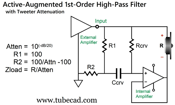
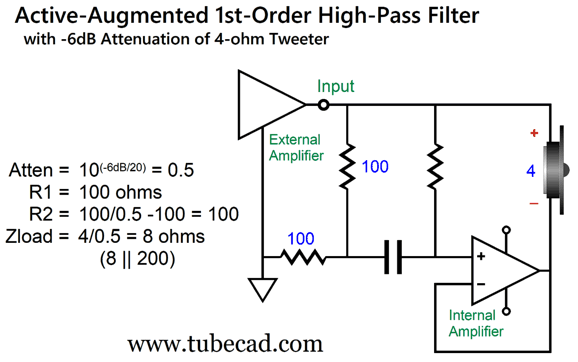
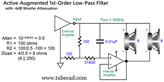
The first step is to calculate the amount of attenuation (Atten) from the desired dB reduction. For example, if we desire -6dB of attenuation, the tweeter needs to see 0.5 or half as much signal. We do the rest of the math and find that both resistors R1 and R2 need to be 100 ohms. We also find that the tweeter's impedance presented to the external power amplifier is doubled; in other words, as far as the external power amplifier is concerned, it doubled. (Actually, we must include the 200-ohm load presented by the two 100-ohm resistors in the load calculation.)
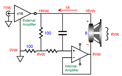
To see how the impedance got increased, let's look at a DC voltage example; first, with no attenuation.
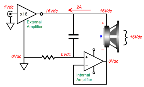
The external power amplifier gets a 1Vdc input signal and amplifies it up to 16Vdc. The loudspeaker driver's 8-ohm resistance prompts a 2A current flow. Now, 16V/2A equals 8 ohms of resistance. Next, we impose a -6dB attenuation.
The driver now only sees an 8-volt voltage drop across its terminals, so it only draws 1A of current, which implies a 16-ohm load resistance, as 16V/1A equals 16 ohms. Is this a major bug? No. Here is why: we can use a 4-ohm tweeter and the external power amplifier will still see an 8-ohm load. As I have often pointed out here before, 4-ohm tweeters usually sound better than their 8-ohm brothers. Why? Half the voicecoil mass. (If nothing else, we could place an 8-ohm resistor in parallel with the 8-ohm tweeter.) Another possible use of the increased impedance would be when we attenuate the woofer. Woofer attenuation, really? Here is an example, say you want to use two 88dB SPL woofers with an 88dB SPL midrange driver in an MTM arrangement, with a low crossover frequency of 500Hz, much like the old Quad model 57.
The two 8-ohm woofers in parallel equal a 4-ohm load, which the attenuation circuit doubles back to 8 ohms. Each woofer's 88dB SPL takes a -6dB hit, but as we doubled the radiating surface area, we gain +6dB in SPL. In other words, a giant step sideways, in terms of SPL. By the way, when we attenuate the signal to the bass buffer, we also attenuate any DC offset from the external power amplifier.
Note the flipped RC filter, as this is a low-pass filter. By the way, I have assumed a puny tube-based external power amplifier, say 16W tops. This is important, as the wattage rating of the attenuator resistors must be factored in our calculations. With a 16W external power amplifier, 1/2W 100-ohm resistors would work; but with a 100W external power amplifier, 3W would be the safer choice. On the other hand, if we place an OpAmp buffer between the two-resistor voltage divider and RC filter, then we could use high high-resistance, low-wattage resistors in the two-resistor voltage divider.
Active-Augmented 2nd-order Crossovers
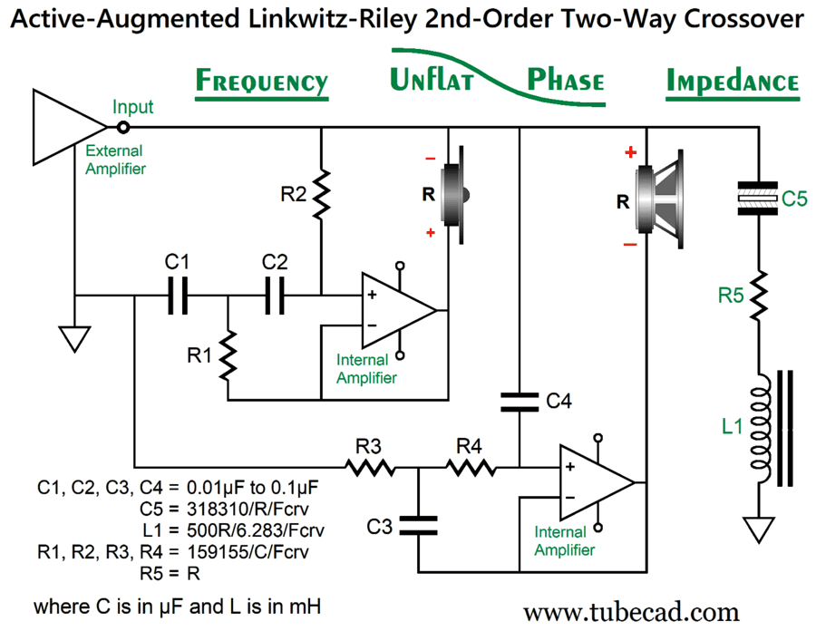
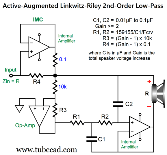
The 2nd-order crossover delivers a good -40dB attenuation per decade of frequency and is frequency-flat, which explains why this is such a popular choice in loudspeakers, in spite of the worse transient response at the crossover frequency. The active-augmented two-way Linkwitz-Riley crossover does offer the feature of using the same resistor and capacitor values throughout the filter sections.
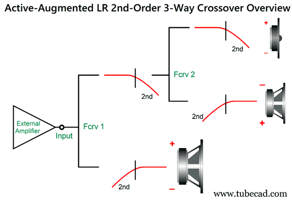
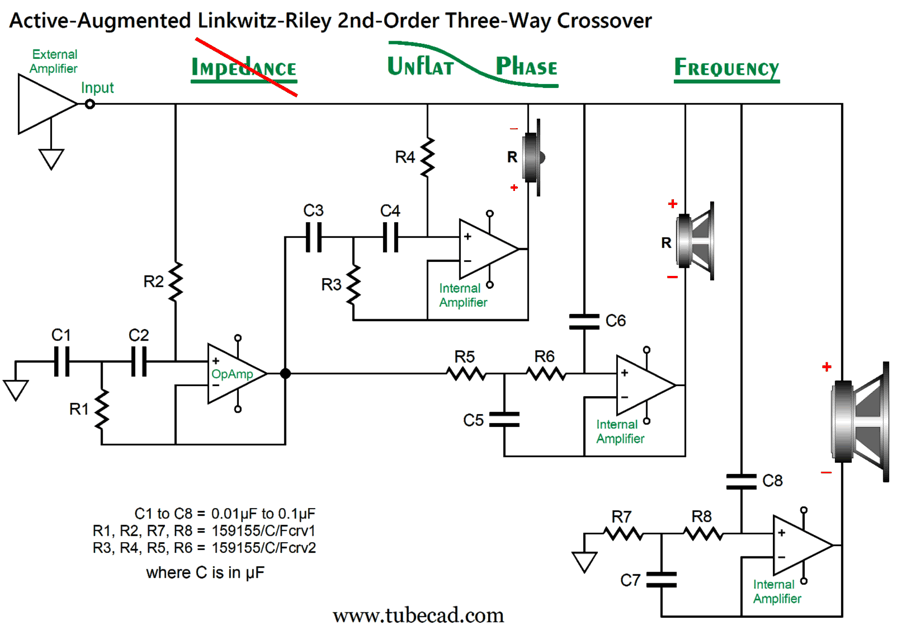
Parts, C5, L1, and R5 are optional, as they impose a flat impedance, which might not be necessary, depending on the external power amplifier used. What about a three-way active-augmented crossover? The big problem that few know about is that the three-way 2nd-order should have a cascaded arrangement. Why? The speaker driver's sum will not yield a flat frequency response otherwise. In addition, since all 2nd-order filters produce 90 degrees of phase shift at the crossover frequency, we must invert the phase of the tweeter in a two-way system; but not in a three-way system, as the midrange driver must be inverted.
I know it looks wrong, as the tweeter seems to get a low-pass filter, not a high-pass filter. Remember that our goal is to deliver deep bass to both terminals of the tweeter, which the low-pass filter achieves. Note that the tweeter sees a cascaded 2nd-order high-pass filtering. This means that the tweeter's cut-off slope steepens to 24dB per octave below the crossover frequency between the woofer and midrange driver.
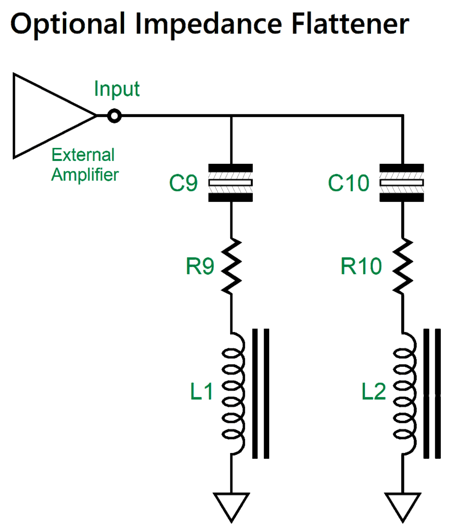
The load impedance presented to the external power amplifier is not flat. Unlike the two-way Linkwitz-Riley active-augmented crossover with the impedance-flattening network, the three-way crossover did not completely relent to my impedance-flattening efforts. If you are up to it, you can add the following circuit.
Of course, not all power amplifiers are overly sensitive to load impedance, in the same way that some tube-based or current-output amplifiers might be. For right now, let's move onto another potential problem with the active-augmented crossover arrangement: overtasking the unity-gain power buffer. We go back to the example of the woofer being fed a 100Hz signal.
The unity-gain buffer's output remains at 0V, as if it were a connection to ground. This way, the woofer experiences the full low-frequency signal across its terminals. Great. The problem, however, lies in the buffer's output stage having to experience all the AC current flow from the external power amplifier. With 16W of output into an 8-ohm load, the peak current flow is 2A. The problem is that the output devices will get much hotter than usual. Why? Usually, when an output stage puts out its peak current flow, the operating output device sees its smallest voltage drop, and wattage equals voltage drop against current flow. (By the way, this does not apply to class-D output stages.) Now, if the external power amplifier is a 3W 2A3-based single-ended power amplifier, we have little to worry about; if the external power amplifier puts out 100W, however, start worrying. One crazy, but possibly brilliant, idea I had is that since the woofer power buffer must simulate ground at DC and low-frequencies, and since the tweeter power buffer must do the same at high-frequencies, why not help them with capacitors and inductors?
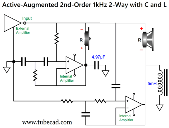
At the 1kHz crossover frequency, the added capacitor and inductor contribute half the required current flow into the drivers. Here are just the tweeter, added capacitor and power buffer output current swings, along with the current delivered by the external power amplifier.
Next, we look at the woofer circuit with the inductor.
Note that the inductor lags behind the external power amplifier, white the tweeter buffer's added capacitor had preceded the input signal. The added capacitor and inductor values are interesting, as the inductor's value (5mH) is four times greater than what the 1st-order crossover inductor value would be (1.27mH), and the capacitor's 4.97µF value is one fourth as large (19.89µF). As the frequency drops, the inductor's phase converges on the power buffer's.
In theory, the inductor would provide all the current flow at DC, but as inductors are made from wire, they present resistance, which prevents the inductor from delivering all the current. One workaround would be to place a series resistor on the buffer's output that matched the inductor's DCR, that way both would still deliver 50% of the current. At the other extreme, the tweeter expects a ground–like termination at ultra-high frequencies, which the added capacitor will behave like. But what about at 100Hz, what will the added capacitor do? Note the phase differences in the following graph.
Yes, most power amplifier hate capacitive loads, but that is because they cannot charge and discharge the capacitance at high-frequencies. In this active-augmented arrangement, the tweeter's power buffer passes along a DC signal, but delivers less and less output as the frequency increases. The woofer's buffer does the inverse, passing along 100% of high-frequencies, but zero voltage swing at DC. Remember this graph?
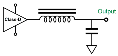
By the way, class-D power amplifiers all hold output inductors and shunting capacitors, as the high-frequency switching noise must be filtered away. Oddly enough, this might make the class-D amplifier the best choice for the tweeter's power buffer, as an unusually large shunting capacitor might prove to be a feature, not a liability.
Haven't I just reintroduced that which we sought to exclude, i.e. big, expensive passive crossover parts. They not be all that expensive, as $2 nonpolarized 5.1µF electrolytic capacitor and a cheap 5mH iron-core inductor could be used in place of the audio-grade $400 parts. How so? The power buffers override thee reactive parts' failings, as the buffers force a 2nd-order Linkwitz-Riley crossover and are only assisted by the added capacitor and inductor. If nothing else, the added parts are not in series with the drivers, as they would be in a conventional passive crossover.
Now, this arrangement with the added capacitor and inductor might be brilliant or it might be a bust. Only experimentation in the real word will reveal the answer. Thus, my preferred workaround to an over-heated buffer's non-class-D output stage is counter intuitive: increase the power buffer's power output.
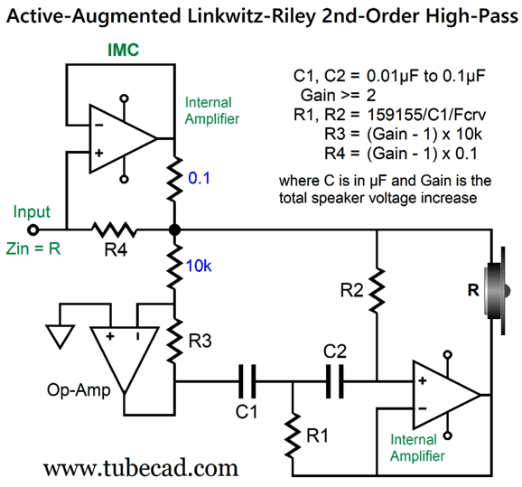
Note the added OpAmp. Its job is to provide an inverted copy of the signal from the external power amplifier. Capacitor C1 and resistor R3 now terminate into its output, not ground. The result is that both the woofer and tweeter now see twice the voltage swing the external power amplifier provides, which increases the SPL by 6dB and quadruples the power delivery into the drivers, as wattage is equal to voltage² divided by resistance (this is true with DC voltages, with AC sinewave voltages divide by twice the resistance). The upside is that the unity-gain power buffer output stages are no longer burdened with having to sink high current with the output stage center at 0V. The downside to this arrangement is that the external power amplifier now sees the driver impedances halved, with 8 ohms becoming 4 ohms. The workaround is to employ one of my famous impedance-multiplier circuits (IMC). We start with the high-pass filter.
The equivalent circuit for the woofer looks like this:
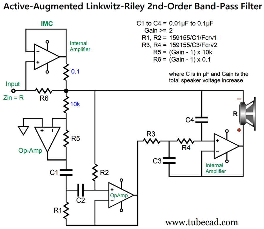
For example, let's say we desire a 12dB boost in SPL, which translates into a fourfold increase in signal voltage across the driver, so we select a gain of 4. This amount of gain results in resistor R3 equals 30k, and R4 equals 0.3 ohms. Without the impedance-multiplier circuit, the external power amplifier would see an 8-ohm woofer as a 2-ohm load. With the impedance-multiplier circuit, the external power amplifier only has to deliver one fourth of the voltage and current swings. What's left to show is an active-augmented circuit for a midrange driver, i.e. a bandpass filter.
An interesting question is should we use just one IMC for up to three drivers (woofer, midrange driver, and tweeter) or should each driver get its own IMC? Since preassembled stereo solid-state amplifier PCBs are far more common than mono PCBs, I would go for one IMC per driver. Moreover, we can then use dissimilar impedance drivers, say a 4-ohm tweeter with an 8-ohm woofer.
Phase-Flat Active-Augmented Crossovers
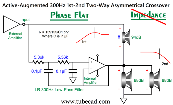
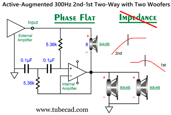
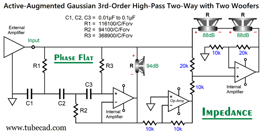
The three driver's outputs sum to both frequency and phase flat. The impedance cannot be flat, as the external power amplifier doesn't power the two woofers at all. The idea here is that a high-quality fullrange driver is the star with a supporting cast of the twin woofers. This way we get to keep the amazing phase-flat quality of the fullrange driver while still getting some deep bass and extra protection for the fullrange driver. (Asking a 6-inch fullrange driver to reproduce 40Hz is never a good idea.)
Note the bumpy 1st-order cut-off slope for the fullrange driver and the 2nd-order slope for the two woofers. By the way, two 88dB woofers yield 94dB when driven in parallel. The logic behind giving the woofers the steeper cut-off slope is that they are slow and thick sounding, so it is best to get them away from the midrange frequencies as soon as possible. Of course, not all woofers are dreadful. In addition, the best fullrange drivers seem to be the most delicate. In other words, we could flip the cut-off slopes.
This arrangement returns us to the smooth high-pass-filter slope for the high-frequency driver and a bumpy 1st-order slope for the low-frequency driver(s).
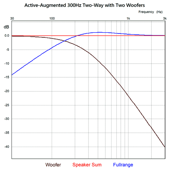
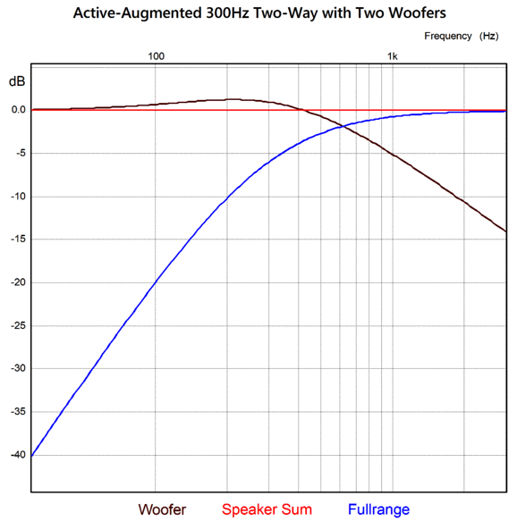
At 30Hz, the fullrange driver is down -40dB relative to the woofer, which means that it sees only 1/100th of the 30Hz signal the woofers see. On the other hand, the woofers went from being down -40dB at 3kHz to being only -14dB down. In other words, high-quality, fast woofers are needed. (I am stunned by the agile articulation offered by some of the paper-cone woofers from GR Research.) I would think about matching the 6-inch fullrange driver with—at the most—8-inch woofers. As this is a phase-flat crossover, we would expect a perfect tone burst at 300Hz out of it —and it does.
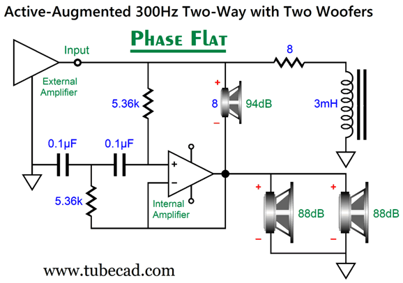
We see three cycles of 300Hz. Note how the fullrange driver puts out so much less output than the woofers. The only real problem with this arrangement is that the load impedance as seen by the external power amplifier is not flat, as it rises with low frequencies, reaching 800 ohms at 30Hz. Once again, this may or may not prove to be a problem, depending on the external power amplifier used. One workaround is to add an inductor and resistor.
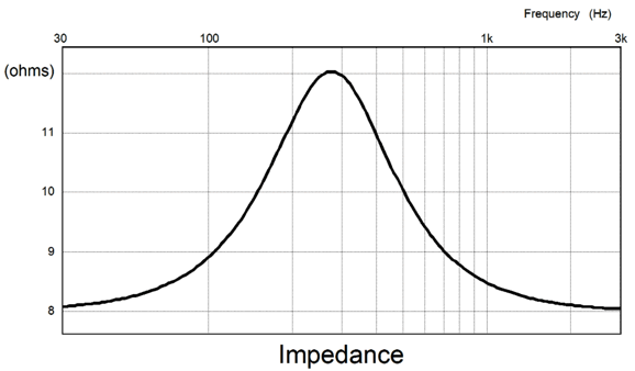
The added resistor and inductor are tuned to 1.414 times the crossover frequency of 300Hz. Here is the resulting impedance graph:
While a 12-ohm peak is not as bad as 800 ohms, it's not perfectly flat. Let's shoot for flat.
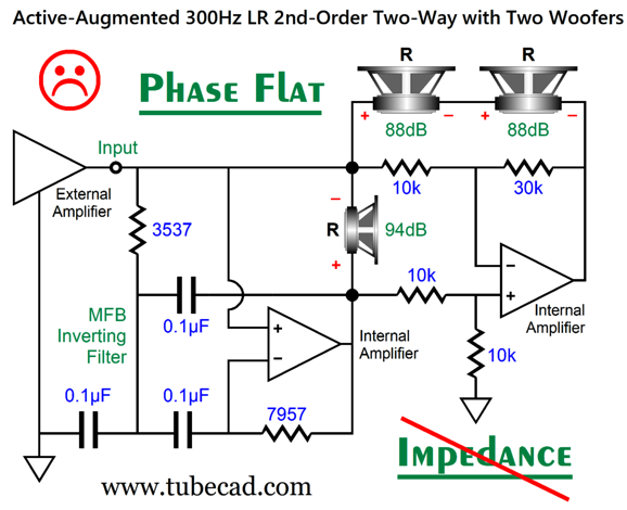
Flat All the Way
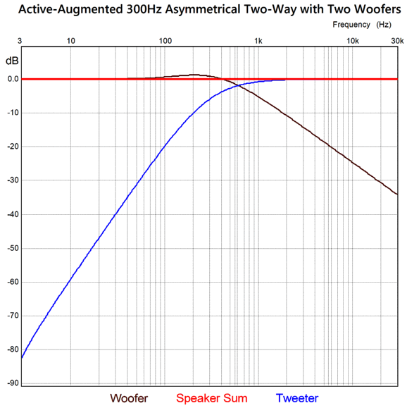
The active 2nd-order high-pass filter is a multiple-feedback filter (MFB) that, unlike the more common Sallen-Key, inverts the input signal at its output. In this design, I deemed this a big feature, as it saved me from having to add an OpAmp. The frequency and phase plots looked great.
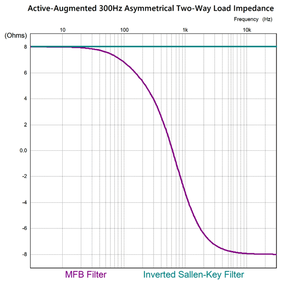
The impedance plot revealed something weird.
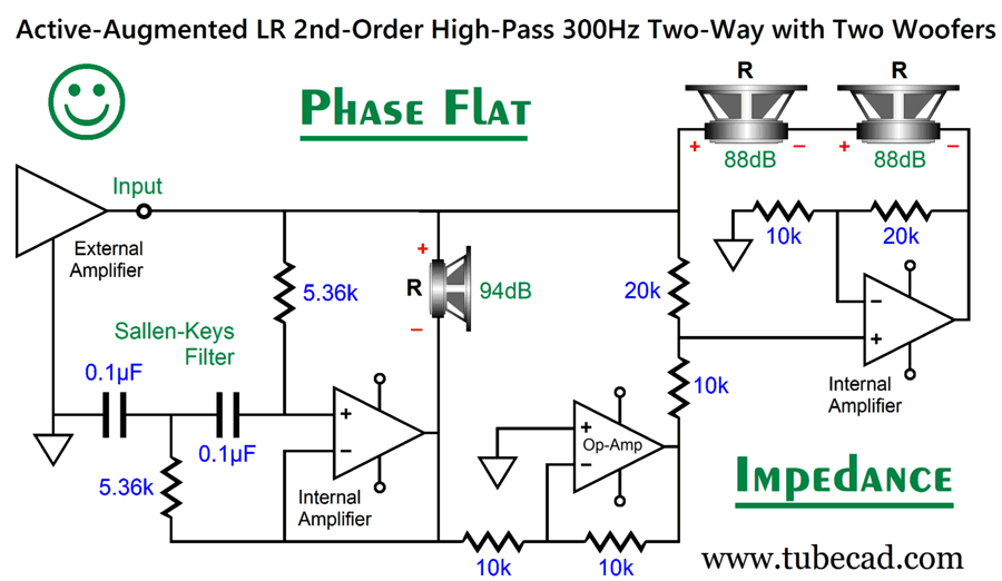
Not good. I set about creating a better active-augmented asymmetrical crossover, which was relatively easy as I had done it before, but I could not find the old SPICE files. (I am reminded of the story of young Mozart, who had dropped a sheet of his latest music composition, but was too lazy to bend over to pick it up, so he simply repeated the inking of the missing music notation. Well, going through my vast array of old SPICE files is far more daunting than bending over.) I simply added the inverting OpAmp stage that I had wanted to avoid and used a non-inverting Sallen-Key 2nd-order Linkwitz-Riley high-pass filter, along with different resistor ratios.
Figuring out the two-resistor voltage divider resistor values and the amount of gain from the internal power amplifier that powers the woofer took some head scratching at first, but once found, looked so obvious, as 2/3 against 3 equals 2. Now, we have it all: flat frequency response, flat phase, and flat impedance. The require math is simple enough: C = 159155/R/Fcrv, where the capacitor is in µF. We can steepen the high-frequency driver's cut-off slope to 3rd-order, with a Gaussian alignment.
Here is a 300Hz design example.
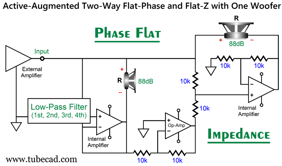
Notice a pattern here? We can universalize this topology. But what about those who only want one woofer, not two? Easy enough:
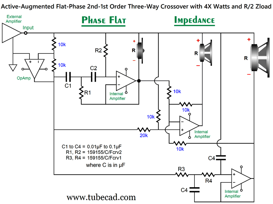
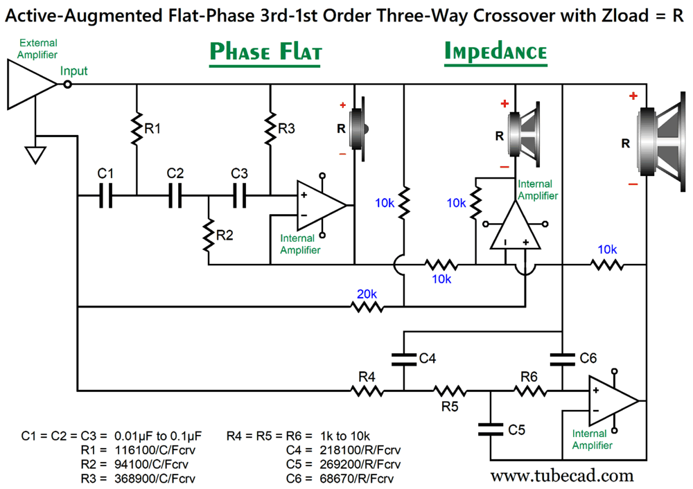
We plug in the desired filter order and alignment, and we still get a flat output. Note the 10k resistors value. The next active-augmented flat-phase arrangement we need to look at is the bandpass filter for a three-way loudspeaker system.
Note that the midrange driver portion of the three-way crossover only requires resistors, no capacitors, as the differential amplifier simply samples the output to the woofer and tweeter and then delivers the needed output to establish a phase and frequency flat summation.
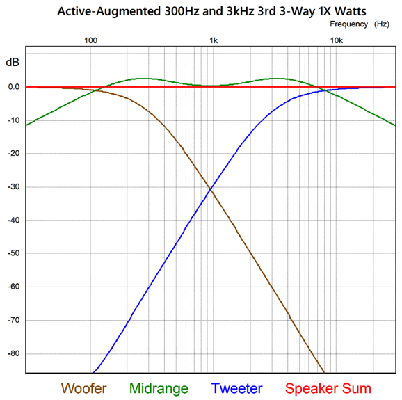
The 3rd-order slopes are nice, as it both gets the woofer out of the midrange and offers good protection for the tweeter. One problem that resurfaces is that of the internal power amplifiers having to eat the peak current flow when their output stages are centered at 0Vdc. In other words, it's time to return to the riddle, conundrum, mystery created by the new Sphinx Element 3 loudspeaker: Just how did they do that?
As we have learned from the Hi-Fi News' review:
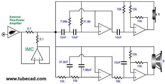
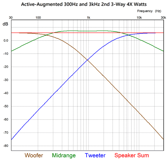
The speaker presents a 16-ohms load impedance and a 94dB SPL with only 0.5W of input power. The first step is to reduce the previous circuit's low-frequency and high-frequency filters to 2nd-order and add some signal gain.
The added OpAmp inverts the external power amplifier's output and results in twice the voltage swing across the drivers and, thereby, quadruples the power delivered.
The driver impedance halves because of the power increase. So how do we go from 6dB of gain to 12dB and from 2 ohms to 16 ohms? Impedance-multiplier circuit to the rescue.
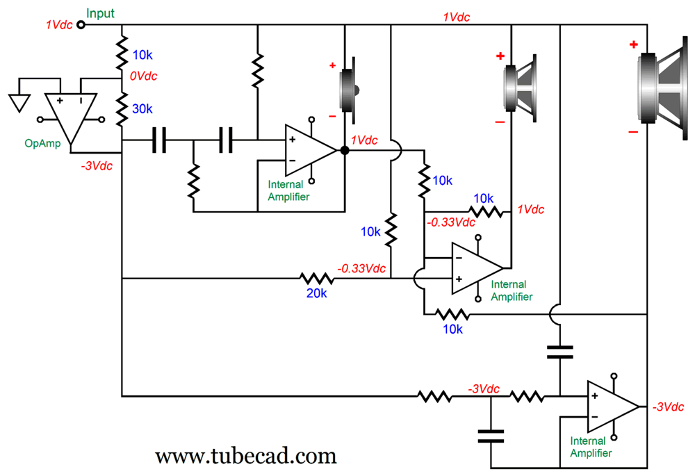
All three drivers see four times the input voltage from the external power amplifier, which implies a 16 times greater wattage. But without the IMC the load impedance would drop to 2 ohms; with the IMC, the external power amplifier only delivers one fourth of the current flow, so the 2-ohm load gets magnified to 8 ohms. A good way to see how this works is to examine DC voltages, but without the impedance-multiplier circuit to enhance conceptual clarity:
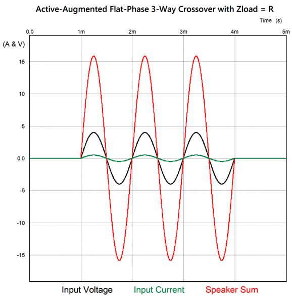
Note the 0V voltage drop across both the tweeter and midrange driver, but a 4V drop for the woofer. Here is a three-cycles tone burst:
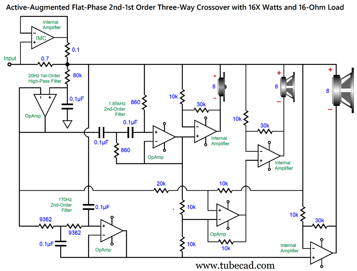
The external power amplifier "sees" a an 8-ohm load and delivers 4V peak at 1kHz and 0.5A peak of current (1W), but the speaker sees 16V peak and 2A peak of current flow, hence 16W. We could have set the impedance-multiplier circuit's current ratio to 1:7, which would have delivered a 16-ohm load impedance for the external power amplifier, as they did with the Sphinx Element 3. (If we desire a 16-ohm load impedance, we replace the 0.3-ohm resistor with a 0.7-ohm resistor.) What's the advantage of a 16-ohm load? First, old classic tube-based power amplifiers with output transformers usually offered three output taps, 4, 8, and 16 ohms. By using the 16-ohm tap, the output voltage increases by the square-root of 2 or 1.414. (Mind you, few modern tube-based amplifiers offer a 16-ohm tap.) Second, solid-state class-AB output stages remain in class-A twice as long with a 16-ohm load. In addition, only a quarter of input signal is needed to drive the loudspeaker to full output, which means that the cheaper and better performing low voltage OpAmps can be used in the filter stages. Here is how we can avoid high-voltage OpAmps by asking the three internal power amplifiers to provide some signal gain:
Most audio-grade OpAmps can easily handle input signals of ±10V, which implies, in this circuit, a peak output voltage swing of 40V that happens to be the peak voltage output of a 100W power amplifier into an 8-ohm load. The review of the Sphinx Element 3 mentioned a low-frequency high-pass filter to prevent infra-sonic signals from being amplified, so I added one. (In addition, it stops DC offsets from the external power amplifier from being passed along and amplified.) Yes, I know this 1st-order high-pass filter looks so wrong, but remember that we treat ground as the input signal in this active-augmented crossover. Just for fun, I also worked out the filter part values for the 170Hz and 1.85kHz crossover frequencies. Note that the external power amplifiers deliver a gain of 1:4, which yields +12dB of gain. It may look like the internal power amplifiers are configured as inverting amplifiers with a gain of only 1:3, +9.5dB not +12dB. They are non-inverting. Remember once again, that in the active-augmented arrangement, the input signal is treated as ground. Now, imagine that I am at some bar near to where an audio show is being held, and that the fellow sitting next to me tells me that he has designed the most amazing loudspeaker ever. After he is done describing its attributes, 16 ohm load and 94dB SPL and phase-perfect active-passive crossovers; and as beer can only be rented, he leaves to relieve himself. Upon his return, I show him this schematic. He blurts out, "What are you, man, some f*cking industrial spy?"
Music Recommendation: Rebecca Pidgeon, The Raven Until recently, the streaming services only offered her album, The Raven, in 16-bit, 44.1kHz. No more, as Amazon Music delivers a 24-bit, 96kHz version. Equally enjoyable, many of the other albums from other Chesky Records artists, such as Ana Caram, David Chesky, Mark Whitfield, Sara K., and Valerie Joyce also got the sonic upgrade. I recommend trying one of the Chesky samplers, such as The Best of 2017 and The American Songbook Vol. 1, and then tracking down the Chesky high-resolution albums of the artist.
//JRB
AI Summary This document discusses innovative active crossover designs in high-end loudspeakers, personal anecdotes, and reflections on audio technology and high-fidelity sound systems. Innovative Active-Enhanced Crossovers Design Principles of Active-augmented Crossovers Challenges and Solutions in Active Crossover Design Practical Applications and Future Prospects Impedance and Power Amplifier Interaction
Benefits of Using a 16-Ohm Load
Active-Augmented Crossover and OpAmp Gain
High-Resolution Music and Audiophile Preferences
Did you enjoy my post? Do you want to see me make it to post 1,000? If so, think about supporting me at Patreon.
User Guides for GlassWare Software
For those of you who still have old computers running Windows XP (32-bit) or any other Windows 32-bit OS, I have setup the download availability of my old old standards: Tube CAD, SE Amp CAD, and Audio Gadgets. The downloads are at the GlassWare-Yahoo store and the price is only $9.95 for each program. So many have asked that I had to do it. WARNING: THESE THREE PROGRAMS WILL NOT RUN UNDER VISTA 64-Bit or WINDOWS 7, 8, and 10 if the OS is not 32-bit or if it is a 64-bit OS. I do plan on remaking all of these programs into 64-bit versions, but it will be a huge ordeal, as programming requires vast chunks of noise-free time, something very rare with children running about. Ideally, I would love to come out with versions that run on iPads and Android-OS tablets.
|
I know that some readers wish to avoid Patreon, so here is a PayPal button instead. Thanks. John Broskie
John Gives
Special Thanks to the Special 91 To all my patrons, all 91 of them, thank you all again. I want to especially thank
I am truly stunned and appreciative of their support. In addition I want to thank the following patrons:
All of your support makes a big difference. I would love to arrive at the point where creating my posts was my top priority of the day, not something that I have to steal time from other obligations to do. The more support I get, the higher up these posts move up in deserving attention.
If you have been reading my posts, you know that my lifetime goal is reaching post number one thousand. I have 365 more to go. My second goal was to gather 1,000 patrons. Well, that no longer seems possible to me, so I will shoot for a mighty 100 instead. Thus, I have just 9 patrons to go. Help me get there. Thanks.
New URL of the GlassWare website |
||||||||||||||


| www.tubecad.com Copyright © 1999-2026 GlassWare All Rights Reserved |