| John Broskie's Guide to Tube Circuit Analysis & Design |
18 January 2022 Post Number 552
Internal Power Multipliers
Paradoxically enough, what is needed, as the loudspeaker enclosure becomes smaller, is more power. With loudspeakers, we might desire several features, such as:
Immediately, we see contradictions; for example, high performance and low cost seldom adhere to any high-end audio product. What many fail to see, however, is that small enclosure size, deep bass, and high efficiency are not menu items that can be cooked into a single dish. We can choose two items, but not three. Here's analogy: cars.
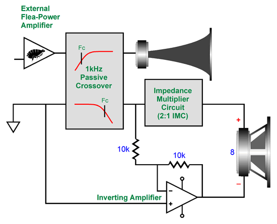
We might desire a tiny price, along with blistering quick acceleration, a top speed three times the speed limit, a magnificently spacious interior, thick steel-wall construction to keep us safe in accidents, an audiophile and autophile's dream audio system, which includes two 1,000W powered 18-inch subwoofers, a refrigerator and microwave, and, of course, phenomenal gas mileage. Good luck. If we forgo a cheap price and great gas mileage, the universe might be able to deliver the other items—but never all of them at once. (I have mentioned the following story here before, but Google let me down, as it could not find the post.) Over a decade ago, I helped a small tube-based audio company with one of their faulty designs. The owner was pleased with the results, as my efforts were successful—and freely donated. He asked if I could design a small loudspeaker that must deliver deep, powerful bass and yield super high efficiency, so that small tube-based amplifiers could be used. My answer was, "No. In fact, no one can, as such a loudspeaker is theoretically impossible with conventional loudspeaker drivers." He didn't believe me. Why should he, as so many other audio gurus told him it was possible? Yet, no small speaker delivering deep, powerful bass along with super high efficiency has appeared in his product lineup—or in any other company's product line. Small speaker enclosures with deep, powerful bass are certainly possible, but they won't be efficient. (See post 461.) Since we cannot expect a flea-power amplifier to deliver the required amount of power into a small loudspeaker enough to produce loud and deep bass, we must make up the difference in wattage with an internal, integral solid-state power amplifier. The assumption here is that the midrange and tweeter offer sufficient efficiency for the flea-power amplifier to drive them entirely; in other words, it is only the woofer that will need boosting.
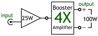
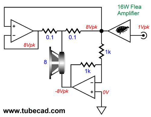
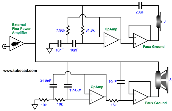
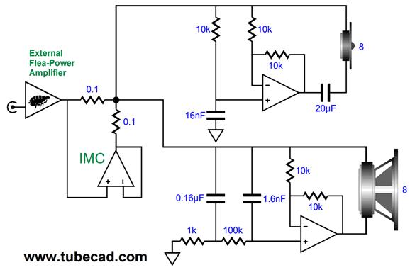
Adding power amplifiers allows us to magnify the flea-power amplifier's output, while still presenting an 8-ohm load to the flea-power amplifier. The first integral power amplifier functions as an impedance-multiplying circuit (IMC), which doubles the woofer's impedance. This is important, as an 8-ohm load effectively appears as a 4-ohm load in this quasi-bridge-amplifier configuration. With the IMC in place, the 4-ohm apparent load impedance doubles to 8-ohms, making the flea-power amplifier happy.
The second, bottom amplifier is configured as an inverting amplifier that delivers the same output voltage swings as the flea-power amplifier but inverted, thereby doubling the voltage swing across the woofer, which in turn quadruples the wattage, as AC power is equal to voltage squared divided by twice the load impedance, or W = V²/2R. Note that the inverting amplifier does not see full-bandwidth input signal, only the frequencies below the crossover frequency.
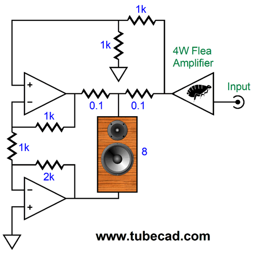
If we look at the circuit with current-referenced glasses on, we see that the flea-power amplifier and IMC deliver each one half of the current flow, while the bottom inverting amplifier must deliver all of the require current flow. In other words, the inverting amplifier will do twice the work and get twice as hot as the IMC's power amplifier. We can arrange the IMC and the inverting amplifier as a balanced-output amplifier, which requires a two-resistor voltage divider to function as an attenuator of the flea-power amplifier's output voltage swings.
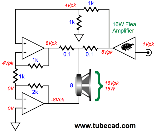
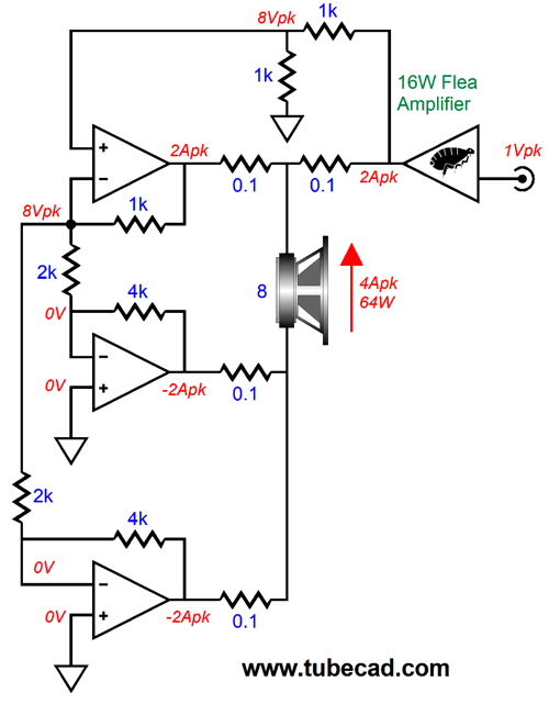
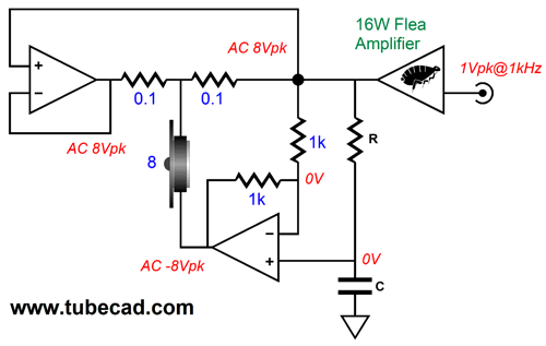
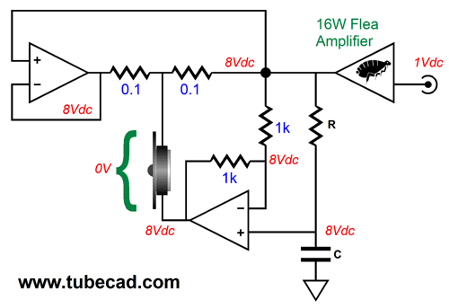
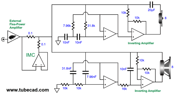
This arrangement works far better with most solid-state power amplifiers, as it limits the input signal voltage swings to the IMC's input. Too large an input voltage will crash the input stage due to cascoded differential amplifiers and constant-current sources and current mirrors employed in the input stage. In addition, most chip amplifier are nowhere near unity-gain stable, most require a gain of at least ten to prove stable. This arrangement allows us to attenuate the flea-power amplifier's output voltage by ten (or much more) and then set the balanced amplifier gain to ten (or much more), resulting in unity-gain. In the example shown above, the attenuation is 0.5 (-6dB) and the gain is 1:2 (+6dB), which returns us to unity-gain. The following schematic shows the AC voltage relationships.
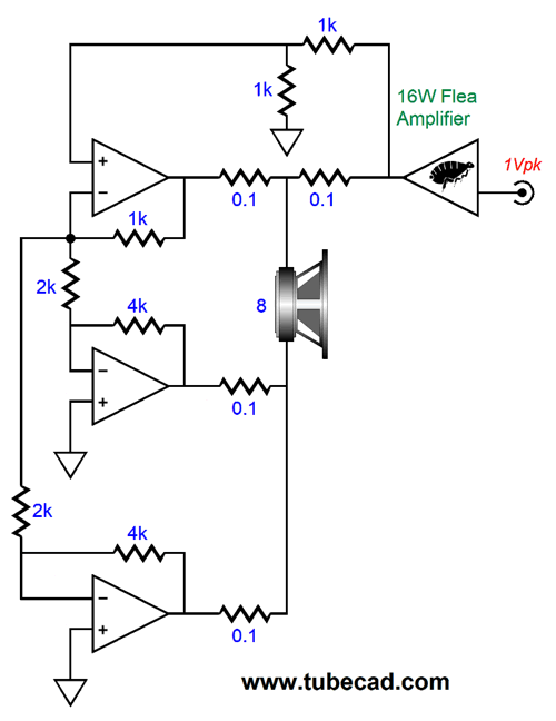
The flea-power amplifier delivers—at its maximum—4W, 8Vpk and 1Apk into 8 ohms. The 50% attenuator reduces the 8Vpk to 4Vpk, which the IMC amplifier amplifies to 8Vpk, while the bottom inverting amplifier puts out -8Vpk, making for a total of 16Vpk across the 8-ohm woofer and 16W of power delivered. If the woofer's SPL rating is 84dB, its effective SPL is now 90dB, bringing it in line with the tweeter. Physics was never cheated, as we had to pay for the increase in effective SPL by providing the needed power augmentation with the integral power amplifiers. As far as the eye can see, it sees a tiny flea-power amplifier and tiny loudspeaker enclosures delivering far deeper and louder bass than would seem possible with a wee amplifier. Since the inverting amplifier must deliver twice the current that the IMC's amplifier, we can double up on the inverting amplifiers.
This time, the flea-power amplifier is a burly brute that delivers 16W, 16Vpk, and 2Apk into 8 ohms. It might appear confusing at first, but the arrangement is simple enough. The two inverting power amplifiers work in parallel, receiving the same input signal from the IMC's negative feedback loop. The two 2k resistors are effectively in parallel, as the inverting amplifier inputs are effectively a faux ground connection; thus, they represent a 1k resistance to the IMC's negative feedback loop, making the IMC's gain equal to two. At the same time, the 2k resistor and 4k feedback resistor define a gain of -2. Since we attenuated the flea-power amplifier output by 50%, the final gain is inverted unity-gain from the two inverting amplifiers. The best power supply arrangement would be an internal bipolar power supply, as the asymmetrical current draw on the power supply precludes our using a two-resistor voltage divider to create a faux ground. Speaking of current draw, here is the current relationships.
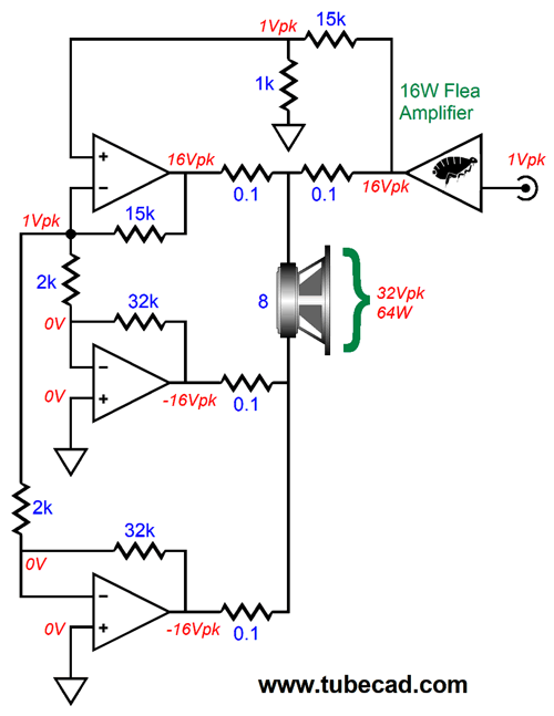
It all makes sense, right? I hope so, as here is an example with greater attenuation and gain.
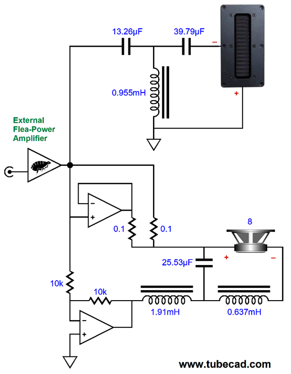
The two-resistor voltage divider (15k and 1k) reduces the flea-power amplifier's output voltage swing by 16, while the IMC and inverting amplifiers develop a gain of 16, as 32k/2k = 16. As all three internal power amplifiers dissipate the same amount of heat, each should get the same amount of heatsink area. Missing from all the schematics is the woofer's passive crossover and its Zobel network. As far as the flea-power amplifier is concerned, it is just attached to an 8-ohm woofer, so we can place an inductor in series with the flea-power amplifier's output and the woofer and its supporting circuitry.
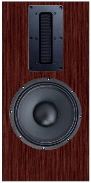
The passive crossover is an asymmetrical type, with the tweeter getting a 3rd-order high-pass filter, while the woofer sees only a 1st-order low-pass filter, with the assumption that the woofer's own natural high-frequency rolloff completes the 3rd-order low-pass filtering. Even if we can pull this off, which won't be easy, the woofer still has an inductor in series with it. Ideally, we would prefer not to have any inductors in series with any loudspeaker driver. We eliminate the inductor by imposing a 1st-order low-pass filter on the integral inverting amplifier's output.
The way this works is that at high-frequencies, the inverting amplifier ceases to be an inverting amplifier, becoming instead a unity-gain non-inverting amplifier. At low frequencies, in contrast, it inverts the flea-power amplifier's output signal. Since a loudspeaker driver is an intrinsically differential device, the woofer only responds to low frequencies, as that is when it sees as a differential signal across its terminals. At high-frequencies, the woofer sees the exact same signal, both in amplitude and in phase. No difference, no sound. The big problem is hitting the target frequency, where the woofer's natural rolloff occurs. What makes it difficult is that few woofers roll-off smoothly. In addition, as the frequency rises, the woofer tends to beam more strongly, almost as if the cone were a horn of sorts, which to a certain extent it is, as the woofer's cone often effectively decouples from the voicecoil at high-frequencies. One workaround that I had some success with is to adhere to the inside of the speaker grill cloth, just in front of the woofer, a round patch of quarter-inch thick felt, slightly smaller than the cone diameter. At low frequencies, the felt is transparent, but it shades higher frequencies, thereby imposing a gentle low-pass filter.
High-Frequency Phase-Shifting Filter
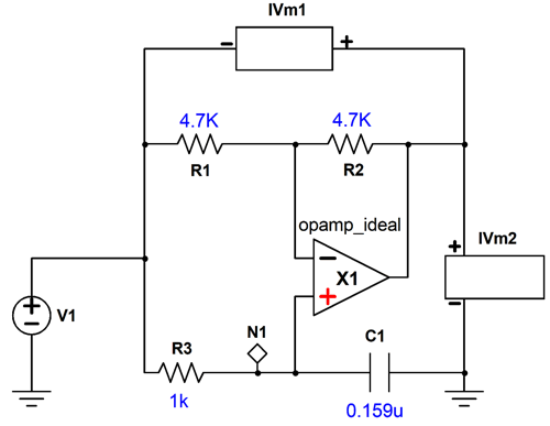
Resistor R and capacitor C set the crossover frequency based on the following simple formula. Frequency = 159155/R/C, where C is in µF. Here is the basic circuit in SPICE.
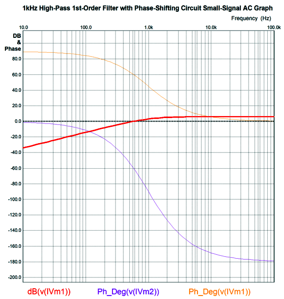
At the left, we see the AC signal source. The two voltage meters allow us to track both the amplifier's output and that output relative to the input. The 4.7k resistors were arbitrarily chosen; they could be replaced by two 10k or two 1k resistors. Here is the resulting SPICE-generated graph.
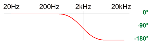
The transition frequency is 1kHz. Although it is hard to see, the output is down 3dB at 1kHz. Note that the amplifier's output undergoes a complete phase reversal at about 100kHz and no phase shift at 10Hz. It is the phase shift that creates the high-pass filter. Let's say the flea-power amplifier put out a huge DC offset voltage of 8Vdc.
Since the bottom, inverting amplifier no longer inverts, it puts out 8Vdc at its output and the delicate tweeter see zero net differential voltage, so it is safe. Okay, now that we have seen both a low-pass filter and high-pass filter action, let's look at the combining of both.
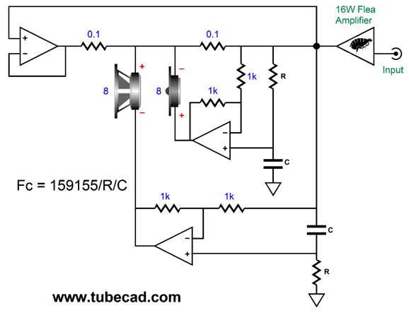
Two inverting power amplifiers are needed, each getting its own phase-shifting circuit. The result is a 1st-order two-way active crossover. As far as the flea-power amplifier is concerned, it is running fullrange into an 8-ohm load. As far as the inverting amplifiers are concerned, they are working into 4-ohm loads. Not only do we get rid of the passive crossover's inductor and large-valued capacitor, we have quadrupled the flea-power amplifier's output power.
Here is the wrinkle: it's never a good idea not the place a capacitor in series with a tweeter. Why? Hum and buzz and DC offsets can kill the tweeter. For example, imagine you knock loose the external power supply plug and the connection is lost and the tweeter's inverting amplifier goes wonky; nothing will protect the tweeter. On the other hand, if we place a safety capacitor in series with the tweeter, the tweeter is likely to survive screw-ups. We might as well put the extra capacitor to some use.
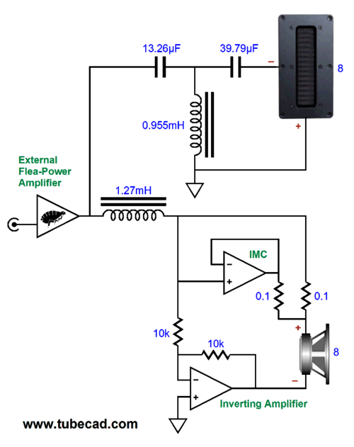
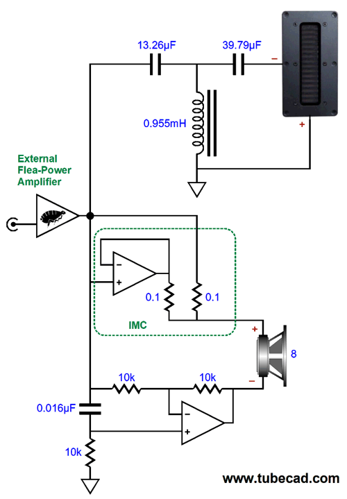
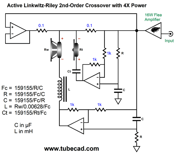
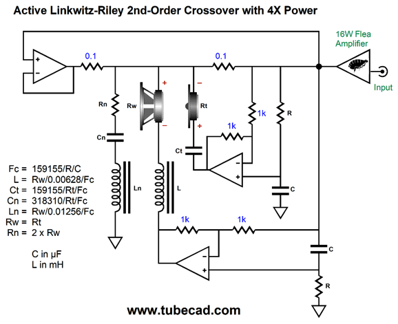
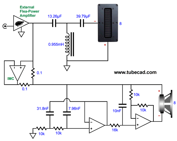
The added capacitor and inductor have created a 2nd-order Linkwitz-Riley crossover. Note the reversal of the tweeter's terminals. Now, both drivers are down -6dB at the crossover frequency and they sum to a flat frequency response, but not a flat phase response, sadly. Still, the steeper crossover slopes better protect the tweeter and prevent the woofer from muddying up the upper midrange. Just like a conventional passive Linkwitz-Riley crossover, the resulting impedance plot is not flat, but peaks at the crossover frequency. My workaround is to place an impedance-flattening network in parallel with the drivers.
The added network results in a flat 8-ohm load for the flea-power amplifier. Some might argue that since we have gone so far down this path, we might as well go all the way to the end, where the flea-power amplifier is not needed, as we would have a fully self-powered loudspeaker. (I believe this is the future, as class-D amplifiers have become cheaper and smaller than high-quality crossover parts.) Do not forget that the flea-power amplifier is actually doing one fourth of the work in this arrangement but its sonic signature will be mimicked by all the integral power amplifiers, as their signal source is the flea-power amplifier's output. For example, a strong 2nd harmonic will remain strong.
Passive-Active 3rd-Order Crossovers
The crossover alignment is a 3rd-order Butterworth, with both a flat summed frequency response and impedance plot. Note that, in this arrangement, both the IMC and the inverting amplifier see the full bandwidth delivered by the external flea-powered amplifier.
Alas, the phase is not flat. We must give up a flat phase response in order to gain a lower crossover frequency and still protect the tweeter. This arrangement has delivered four times the power into woofer—which is welcome—but we still have a lot of huge capacitors and inductors in the signal path. It's a shame to have all this active solid-state circuitry and not also get an active crossover. Well, this situation irked me, but no solution seemed possible. Of course, we could just treat the flea-power amplifier as a robust line-stage amplifier, using its output voltage as the signal to drive an active crossover, but not deliver any power into the loudspeaker drivers, as that task would be entirely taken up by the integral power amplifier, which would function as unity-gain power buffers. Before turning off the light and falling asleep, it hit me. IT being the solution, a dang clever solution, the sort that makes me happy for days. Let's start with no impedance-multiplier circuit (IMC). We assume a woofer and high-frequency driver with equal SPL per watt at one meter. Next, we realize that we cannot place any component in series with the flea-power amplifier's output. So how do we impose an active crossover? We place the circuitry in driver's return path to ground.
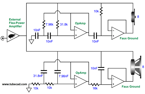
The two internal power amplifiers are configured as unity-gain buffers, while the two OpAmps function as 2nd-order filters with a Q of 1. Following each OpAmp is an RC filter tuned to the same crossover frequency, thereby creating a 3rd-order filter with a Butterworth alignment whose Q is 0.707. The two internal power amplifiers effectively function as frequency-sensitive faux grounds. Unlike a proper ground that experiences zero voltage fluctuations, these two faux grounds vary between acting like a proper ground and acting like a unity-gain buffer, a buffer that functions in phase with the flea-power amplifier's output. The result is that the woofer sees all of the flea-power amplifier's output voltage swings at low frequencies, but at high frequencies it sees the same signal at both its terminals, so it ignores these frequencies, as they are invisible to it. Conversely, the tweeter sees all of the flea-power amplifier's output at high frequencies, but at DC and low frequencies, it sees the same voltage at both its terminals, to which it is blind. Since no power increase is forthcoming, the two internal power amplifiers need only be able to swing the same voltage swings that the flea-power amplifier provides; for example, 8Vpk for a 4W amplifier and 16Vpk for a 16W amplifier. What have we gained in this arrangement? To start with, precision, as 1% resistor and capacitors are readily available for the active crossover, whereas passive crossover capacitors are seldom sold in 5% tolerance, with 10% and 20% large-valued capacitors being the norm. In addition, a single high-quality, large-valued crossover capacitor or inductor can cost over $100. The downside to my solution is that it requires unity-gain power buffers, which are rare. As far as I know, all of the Burr-Brown OPA5XX chip amplifiers are unity-gain stable. And, of course, we can build our own power buffer with discrete components. One additional problem I see is that the high-frequency driver is not protected from amplifier turn-on thumps and broken ground connections. The workaround is to give this driver a crossover capacitor that completes the 3rd-order filter and protects the driver.
Yes, this added capacitor should be a high-quality type, along with being tight-tolerance, but we have eliminated one OpAmp. By the way, if we desire extra power delivery, then we must reintroduce the IMC, as doubling the voltage swings across the loudspeaker drivers effectively makes 8-ohm drivers appear as 4-ohm drivers to the external flea-power amplifier.
The unity-gain power buffers are no more, having been replaced by inverting power amplifiers with unity-gain, i.e. -1. The IMC impedance ratio is set to 2 to 1, so the effectively 4-ohm loads appear as an 8-ohm loads to the flea-power amplifier. We can, of course, mix and match. For example, we can retain the unity-gain power buffer for the high-frequency driver, while giving the woofer both the IMC and the inverting power amplifier. The natural assumption is that the high-frequency driver offers a higher SPL than does the woofer. Naturally, this arrangement could be reversed, with the woofer being the more efficient. Let's say we plan on using a 3-inch fullrange driver for the highs and a ten-inch woofer for the lows, with a crossover frequency of 500Hz. In this situation, I can easily imagine the fullrange lagging behind the woofer in SPL by 6dB. Still, a much more likely arrangement is a hotter high-frequency driver, say a horn-loaded driver, coupled to a lower-efficiency woofer.
Another possible example could be the famous Heil air-motion transformer (AMT), which can be bought for less than $200 each. It's SPL is a roaring 92dB. The only problem with this midrange/tweeter is that its impedance is 4-ohms. My cute little flea-power amplifier, however, does not hold a 4-ohm tap, only an 8-ohm tap.
An 8-ohm version of the ATM is made by Aurum Cantus, their AST25120 Aero-Striction driver, which also offer a wide bandwidth of 700Hz to 30kHz and an SPL of 98dB! Mercy. Mercy. Mercy. The AST25120 data-sheet recommends a crossover frequency of 1kHz.
Okay, say we opt for this high-frequency 98dB driver, what should the SPL be for the woofer? Since the woofer will see twice the voltage swing from the flea-power amplifier, it gains 6dB in SPL; thus, we subtract 6dB from 98dB and get 92dB, which is the desired SPL for the woofer. Although we can find 92dB woofers, they will be large, as in at least 10-inch cones. A workaround might be to use two 4-ohm woofers wired in series, as we would gain a 6dB increase in SPL from the doubled radiation surface. In other words, two 6-inch 4-ohm woofers could deliver 6dB more SPL than a single 6-inch woofer. Indeed, we can probably get away with using two 92dB 4-ohms woofers. If that last sentence seemed wrong, then read post 468. Here is a snippet from it:
In other words, the commonly rated 92dB 4-ohm woofer actually puts out 3dB less with 1W at 1M. The 92dB rating obtains by delivering 2W into the 4-ohm woofer. Well, the high-frequency driver in this example gets 1W (i.e. 2.828Vavg or 4Vpk), which would only produce an SPL of 89dB from the 4-ohm "92dB" woofer. Since this arrangement increases the power the woofer sees by fourfold, i.e. 1W to 4W, the 92dB actually results, as a doubling of power results in a 3dB increase in SPL; and since we have two woofers, thus twice the radiating surface, we get an additional 6dB boost in SPL, bring us to 98dB. By the way, if you think replacing your 100W amplifier with a 200W amplifier will make a huge difference in playback volume, expect to be disappointed, as the increase is only 3dB. To arrive at a perceived doubling of sound volume (+10dB), you need to buy a 1,000W amplifier. I remember friends telling me that they replaced their wimpy amplifier with a vastly more powerful one, say replacing a 38W power amplifier with a 45W amplifier, and how their system thundered now. Did it? The difference between 38W and 45W probably cannot be reliably heard—not even by professional audio equipment reviewers writing for prestigious audio magazines, as the difference is only 0.73dB (a difference of 24.66Vpk to 26.83Vpk.), which is less than the 1dB standard as the smallest perceptible difference in laboratory settings. In contrast, going from a 38-caliber bullet to a 45 caliber makes a huge difference, with the 45 slug delivering twice the foot-pounds of energy. Before leaving this topic, I must point out that we can implement both a 2nd-order and 4th-order active crossover with the faux-ground/power-increasing arrangement. Here is a 2nd-order example, with a Linkwitz-Riley alignment and a crossover frequency of 1kHz.
Note that no OpAmps were needed, just two internal power amplifiers. The impedance-flattening network is needed to prevent the typical Linkwitz-Riley crossover impedance spike at the crossover frequency. Once again, the tweeter gets a passive crossover capacitor along with the active filter, both of which combine to form a 2nd-order Linkwitz-Riley crossover, while providing extra protection for the tweeter. Okay, fasten your mental seatbelts before moving on to the next section.
Patreon
Phase-Flat 2nd-order Crossover
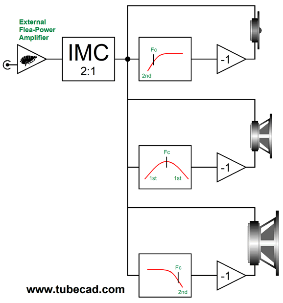
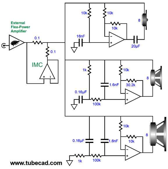
We can easily add a filler driver and its required band-pass filter to the previous design example. First, let's see an overview.
Now, we can see how to implement it.
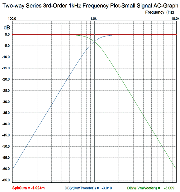
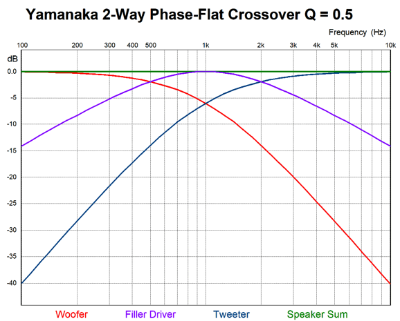
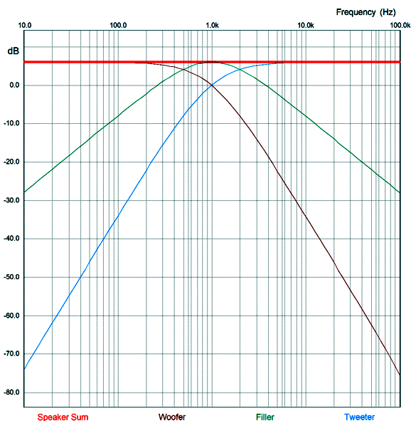
The crossover frequency is 995Hz (close enough to 1kHz for government work). Three integral inverting power amplifiers are used. The filler driver's amplifier's gain is set higher than inverted unity-gain to compensate for the band-pass filter's attenuation (i.e. insertion loss). Nonetheless, all three drivers see the same doubling of the flea-power amplifier's output voltage swings, thereby quadrupling the power from the flea-power amplifier. Note that all three drivers are wired in phase with each other. Here is the resulting graph.
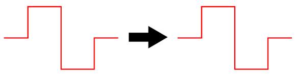
The woofer and high-frequency driver see 2nd-order cutoff slopes, while the filler driver sees gentle 1st-order slopes. Both the impedance and phase are flat. A flat phase response means that the loudspeaker can pass a square wave.
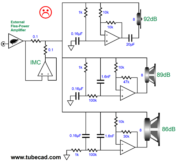
A 1Vpk square wave at 1kHz comes from the flea-power amplifier's output, so the internal inverting amplifiers produce twice the voltage swing. Yet, the tweeter sees peak voltage swings of 4Vpk, while the filler driver sees close to 3Vpk. This is the result of the reactive parts within the filters. Fortunately, we listen to music, not square waves. Still, a flat phase response is a highly desirable feature in a loudspeaker, as it results in better imaging and less distortion. Yes, distortion, the distortion produced by phase-shifting crossovers is dynamically produced, but not statically. In other words, if we attach a sine-wave generator and measure the distortion of a steady signal, we won't measure it. If, on the other hand, we apply short tone bursts and capture the loudspeaker's output on an oscilloscope, we will readily see a garbled signal. Well, music is much closer to tone bursts than it is to a steady sine wave. One feature of this passive-active arrangement is that we can make adjustments to the gains of the inverting amplifiers, without wasting power in a passive padding network's resistors. For example, the tweeter might present an SPL of 91dB, while the filler driver only delivers 88dB and the woofer lags behind at 85dB. The following schematic show how all three drivers are brought in in line.
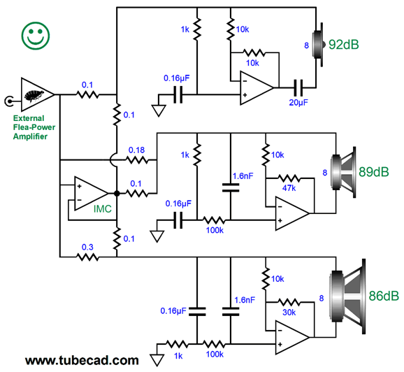
The filler driver and woofer get a "hotter" signal than the tweeter. The feedback resistor values needed to accomplish this feat may seem off, but they are not. In the case of the filler driver's booster inverting amplifier, the band-pass filter incurred an insertion loss that must be added to the -3dB SPL discrepancy between the filler driver and the tweeter. The woofer needs to see twice the voltage swing that the tweeter sees, which the 30k feedback resistor delivers. Unfortunately, the impedance plot is no longer flat due to the three differing gains. With 8-ohm drivers throughout, the impedance drops to 4-ohms at low frequencies. This is not ideal, so the better route to follow is to alter the IMC ratios for each driver.
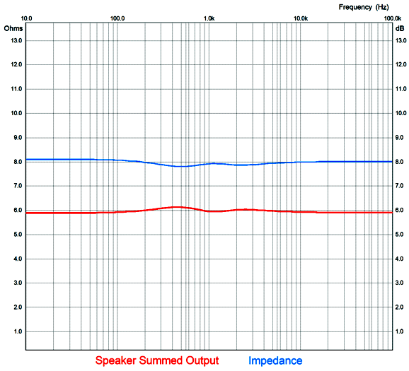
Note the IMC's 0.18 and 0.3 ohm resistors, which produce a flat impedance plot.
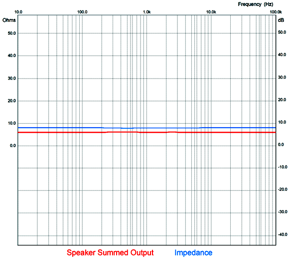
The frequency response plot is not ruler flat, but what loudspeaker driver is? None. Rather than 1dB increments on the Y axis, most frequency-response plot graphs use 10dB or 20 dB increments. Here is what graph shown above looks like with 10dB increments.
Same plotlines, but an altogether different impression.
Music Recommendation: Joshua Redman Quartet's MoodSwing //JRB
User Guides for GlassWare Software
For those of you who still have old computers running Windows XP (32-bit) or any other Windows 32-bit OS, I have setup the download availability of my old old standards: Tube CAD, SE Amp CAD, and Audio Gadgets. The downloads are at the GlassWare-Yahoo store and the price is only $9.95 for each program. http://glass-ware.stores.yahoo.net/adsoffromgla.html So many have asked that I had to do it. WARNING: THESE THREE PROGRAMS WILL NOT RUN UNDER VISTA 64-Bit or WINDOWS 7, 8, and 10 if the OS is not 32-bit or if the OS is 64-bit. I do plan on remaking all of these programs into 64-bit versions, but it will be a huge ordeal, as programming requires vast chunks of noise-free time, something very rare with children running about. Ideally, I would love to come out with versions that run on iPads and Android-OS tablets.
|
I know that some readers wish to avoid Patreon, so here is a PayPal donate button instead. Thanks. John Broskie
John Gives
Special Thanks to the Special 85
I am truly stunned and appreciative of their support. In addition I want to thank the following patrons:
All of your support makes a big difference. I would love to arrive at the point where creating my posts was my top priority of the day, not something that I have to steal time from other obligations to do. The more support I get, the higher up these posts move up in deserving attention.
If you have been reading my posts, you know that my lifetime goal is reaching post number one thousand. I have 448 more to go. My second goal is to gather 100 patrons. I have 15 patrons to go. Help me get there.
Only $9.95
The Tube CAD Journal's first companion program, TCJ Filter Design lets you design a filter or crossover (passive, OpAmp or tube) without having to check out thick textbooks from the library and without having to breakout the scientific calculator. This program's goal is to provide a quick and easy display not only of the frequency response, but also of the resistor and capacitor values for a passive and active filters and crossovers. TCJ Filter Design is easy to use, but not lightweight, holding over 60 different filter topologies and up to four filter alignments: While the program's main concern is active filters, solid-state and tube, it also does passive filters. In fact, it can be used to calculate passive crossovers for use with speakers by entering 8 ohms as the terminating resistance. Click on the image below to see the full screen capture.
Tube crossovers are a major part of this program; both buffered and un-buffered tube based filters along with mono-polar and bipolar power supply topologies are covered. Available on a CD-ROM and a downloadable version (4 Megabytes). Download or CD ROM
|
|||


| www.tubecad.com Copyright © 1999-2022 GlassWare All Rights Reserved |