| John Broskie's Guide to Tube Circuit Analysis & Design |
| March 03 2026 | Post Number 634 |
||||
Pursuit of the Astounding
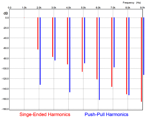
Based on this graph, the THD (total harmonic distortion) meter tells us that this push-pull amplifier offers far less distortion than its single-ended brother. As a result, most believe that this implies that this push-pull amplifier must sound better than the single-ended amplifier. Ten minutes of actually listening to music played through both amplifiers, however, would reverse that judgement. Why? The single-ended amplifier sounds more natural, as that is what we largely encounter in nature. In nature, vibrating things tend to give rise to an attenuating cascade of the harmonics. Even air imparts a 2nd harmonic distortion. In contrast, those things that don't create a smooth cascade of harmonics—such as the breaking glass bottles and the snapping of tree limbs, crinkling foils, screeching animal cries—our ears find offensive. In other words, while single-ended circuits do not contribute to the problem of preexisting push-pull harmonic structure, they cannot actively undo that preexisting structure, beyond the reintroduction of some of the missing 2nd and 4th harmonics. In order to go further in adding a countervailing harmonic structure, we need the actual inverse of the saw-tooth harmonic structure of the push-pull circuit. I have labeled this the "Astoundingly-Atypical" harmonic structure.
The first time I encountered this ever-so rare harmonic structure in a SPICE-generated Fourier graph, I didn't see it, it being the astounding inverse of the typical push-pull harmonic signature. Instead, I thought I was looking at the drearily familiar push-pull signature. It's often difficult to see what you never expect to see. Speaking of vision, I often resort to analogies involving vision when trying to explain some sonic event. Of course, all analogies ultimately fail, as they can never be exact one-to-one replicas of what is being analogized. If they were 100% exact replicas of what is being analogized, they would no longer be analogies, but the things themselves. But as the saying goes, a picture is worth a thousand words. Words used in audio reviews are seldom as pellucid and apt as the reviewer believes. Just what is a "orange" midrange or "juicy" highs or "drive" or "energy"? A friend once asked if I had read the latest issue of a famous audio magazine. I explained that I had wearied of the magazine and didn't renew my subscription. He then, behind my back, bought me a new subscription. Why? He explained that we needed to share the same audio-sonic vocabulary when describing audio gear, which religious reading of the magazine would ensure. Indeed, I am surprised that since the advent of image-manipulation software, such as Photoshop, that audio-review magazines and websites haven't made use of it to give a visual analogy of the sonic presentation of a loudspeaker or phono cartridge. For example, we might take a photo of a jazz quartet, and use the bottom of the photo to represent the bass frequencies and the top as the high-frequencies. If the loudspeaker is bass heavy and highs light, we could apply a gradient of saturation from bottom to top, with the top portion of the photo thinned out or even erased. In fact, a horizontal band of erasure could represent a suck-out at some band of frequencies. If the loudspeaker proves incapable of producing a stereo image, we could apply some transparency overlay to the center of the photo. The photo's color temperature and focus could be altered as well. Well, here is an analogy that gets at what I am striving after.
Imagine that eyeglasses had only been made to keep dust out of our eyes, so the flattest lenses were deemed the most desirable. Then one day, an enterprising individual suggests that if the eyes are not themselves perfect, then the lenses should no longer be flat, but ground to an inverse imperfection, so that the poor eyesight might be remedied. After the laughing ends, the scolding begins. "Don't you know that perfect eyeglasses are perfectly flat, neither adding nor subtracting the incoming light. Neutral is perfection itself. Other than drug addicts, why would anyone want to look through a distorted glass lenses?" Astoundingly atypical is not neutral. Guilty as charged. That is the whole point; it is a corrective measure, just like non-flat lenses in your eyeglasses. Okay, enough preamble. Recently, I wondered how much single-ended amplification and single-ended correction would be needed to undo the severe push-pull harmonic structure of a class-B amplifier. Here is where SPICE truly becomes useful, as getting the answer does not require heating up the soldering iron.
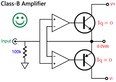
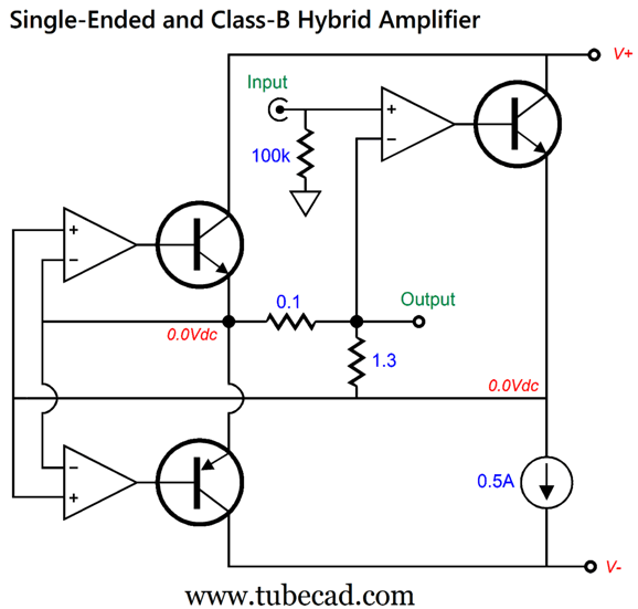
To begin with, true class-B output stages are rare, super rare, as most push-pull output stages run in class-AB, albeit sometimes in very light idle current. Ideal class-B operation means zero idle current flow through the push-pull output devices. (There are no single-ended class-B amplifiers.) The only possible exceptions I can think of are some older OpAmps and some old public-address power amplifiers. We can, however, make a true class-B output stage with the aid of two OpAmps and two power transistors.
This is true class-B operation, as both output transistors idle at zero current. If either transistor starts to conduct, the output voltage will stray from zero volts, causing the master OpAmp to shut down its enslaved and offending transistor, resulting in a race to zero.
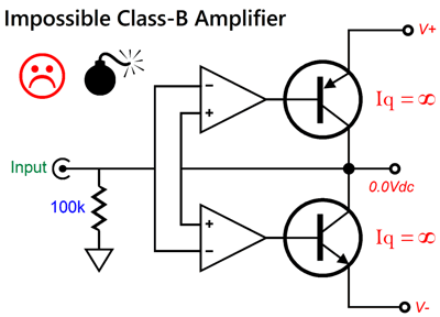
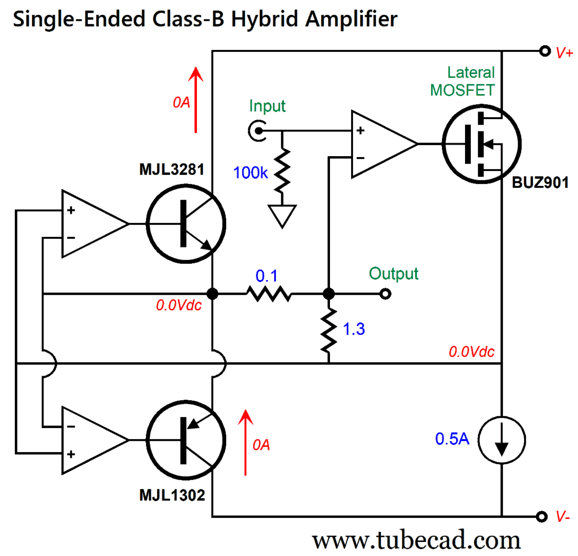
In contrast, the following circuit arrangement does the opposite and fails as a result.
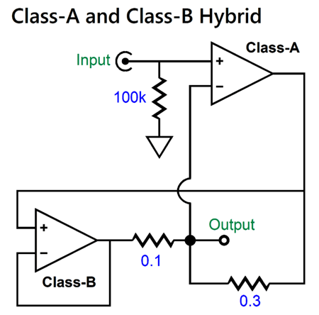
If either transistor starts to conduct, the output voltage will stray from zero volts, and the opposing master OpAmp will turn on its enslaved transistor, and a current battle commences, ending in the blowing of fuses or transistors. Okay, here is the core idea that combines class-A and Class-B, but give the steering wheel to the class-A amplifier:
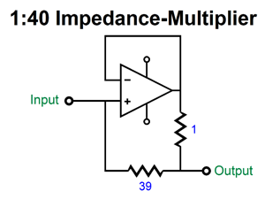
Let's assume that the class-A amplifier is also a push-pull power amplifier. It delivers one fourth of the amount of the current the loudspeaker sees, while the class-B, push-pull amplifier delivers three times more. With 64W of output into an 8-ohm load, the class-A amplifier delivers 1Apk, while the class-B amplifier puts out 3Apk. The 0.1-ohm and 0.3-ohm resistors set the current ratio of 3 to 1. In addition, they create an impedance-multiplier effect, where the external load appears four times greater in impedance to the class-A amplifier. In other words, this circuit is a variation on the impedance-multiplier circuit (IMC).
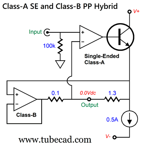
In the 0.1-ohm and 0.3-ohm arrangement, if both amplifiers saw the same input signal, we would expect a 75% and 25% mix of harmonic distortions, i.e. with 75% winning. But as the class-B amplifier gets its input signal from the class-A amplifier's output, the class-A amplifier controls the class-B amplifier and, as a result, imparts its harmonic structure upon the output. For a class-A push-pull output stage to deliver a current flow of 1A requires that the output stage idle at half the peak output current; in this example, 0.5A. What if the class-A amplifier were a single-ended type? Well, if nothing else, we could expect a lot of heat generation from the single-ended amplifier. For example, for 64W of output into an 8-ohm loudspeaker, the amplifier would need to put out a peak voltage swing of ±32V, which implies power-supply-rail voltages of at least ±35V. A single-ended output stage that delivers 1A of peak output current must idle at least 1A. This means that the output device and its 1A constant-current source must dissipate a total of at least 70W at idle. If we expect 4-ohm loudspeaker to be driven, the single-ended dissipation must double (140W), along with the idle current. On the other hand, we could alter the resistor ratio, thereby lessening the current demands on the single-ended output stage.
The current ratio is now 1:13 and the impedance ratio is 1:14. The single-ended output stage's idle current seems to only been halved, but it is actually quartered, relative to a 4-ohm load. In fact, the constant-current source's idle current should be 0.57A to conform to the current ratio. How so? With 8A peak into a 4-ohm load (128W), the idle current should equal 8A/14 or 0.5714A. The next step is to incorporate the OpAmp-based class-B output stage into this arrangement.
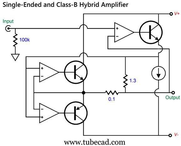
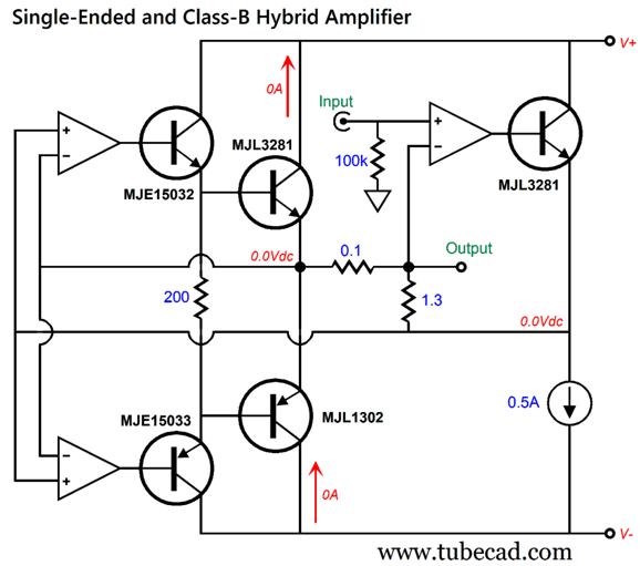
As I look at this schematic, I can easily imagine that few will not see the underlying topology, so here is the same circuit differently drawn:
(I hope that this helped. By the way, this trick of redrawing a schematic also works with sentences that elude comprehension; just rewrite it. If it cannot be intelligibly be rewritten, it probably was actually devoid of semantic content to begin with.) Note that this arrangement yields a power buffer, not an amplifier, as there is no voltage-signal gain, only current gain. Think of it as an output stage that could be nested within a larger amplifier circuit or as a power buffer for use with a tube-based input stage. And do not get hung up on the output transistor, as a lateral MOSFET could be used instead.
The more common vertical MOSFET should not be used, as they require much higher biasing voltages. If you worry about the OpAmps not being able to drive the power transistors to full output, do not worry about the single-ended half of the circuit, as this single output device need only deliver peak output current swings of 1A, which divided by the transistor's beta becomes light enough a load for most high-quality OpAmps. The class-B output transistors, on the other hand, will prove hard to drive. The workaround is to the use the conventional emitter-follower driver circuit.
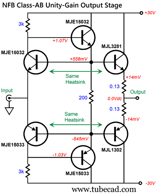
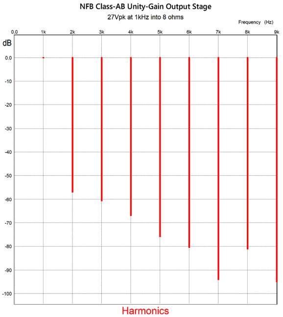
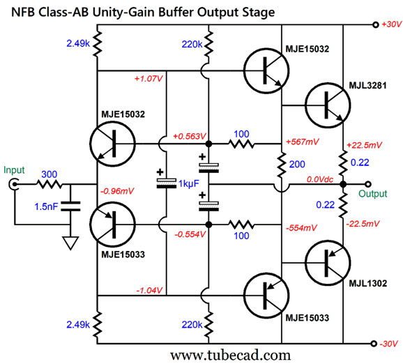
The MJE15032 and MJE15033 pair is commonly used in this arrangement in many solid-state power amplifiers. Depending on the power-supply rail voltages, high-voltage OpAmps will be needed, although they could be replaced by discrete electronic devices, such as FETs and transistors. On the other hand, if the power-supply rail voltages to not exceed ±20Vdc, the number suitable unity-gain-stable OpAmps is staggering. I used, however, power-supply rail voltages of ±30Vdc. In SPICE simulations, we get the following Fourier graph:
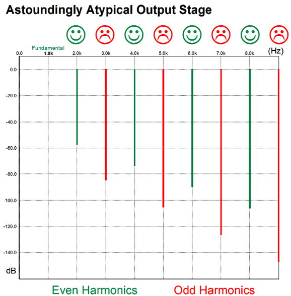
Note the "Astoundingly-Atypical" harmonic structure, with the odd harmonics attenuated more than the even harmonics. With 16W of output, we get this graph:
And at full output (80W) working into a 4-ohm load, we get this graph:
Are you noticing a pattern here? Quite astounding. If we examine the current-conduction graph, we see the following:
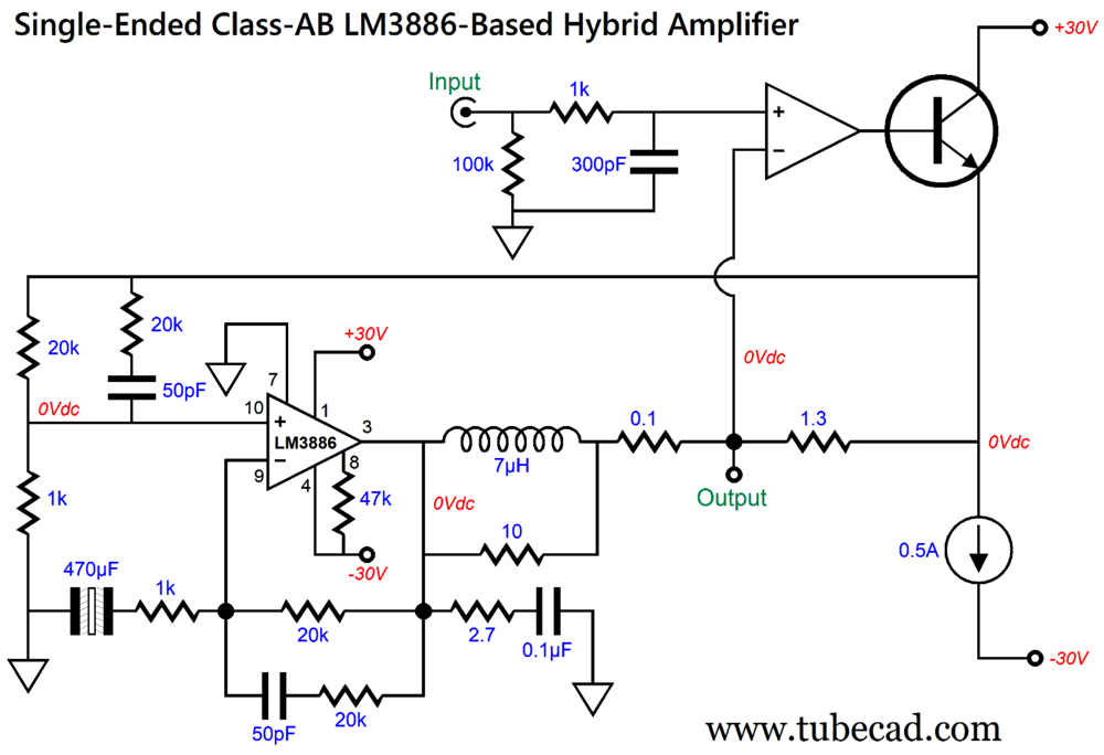
Note the class-B output transistors do shut off completely, while the single-ended NPN transistor approaches 1A and nears zero, but never drops below 50mA. I had to increase the current ratio to 1:13 to achieve this result with the 4-ohm load. If we had restricted the load impedance to just 8 ohms, the ratio could have been set to something lower or the single-ended idle current ratio could have been decreased. I must point out, however, that these results are too good, as the SPICE model I used for the OpAmps was for the "ideal OpAmp," which functions at the very limits of the SPICE engine to deliver perfection. In other words, it offers near infinite gain and zero output impedance, and it can deliver near infinite bandwidth, current, and voltage. Reality differs. Still, it is directionally correct. I mentioned before that we could replace the OpAmps with discrete devices, which was true. But we might replace the class-B output stage with a power IC amplifier, such as the LM3886.
The LM3886 is nowhere close to being unity-gain stable, so we must first attenuate its input signal before it amplifies it back to unity-gain. Sadly, I do not have a compatible SPICE model for the LM3886. Another thought I had was that we could add some triode magic.
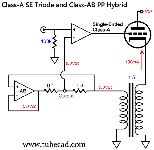
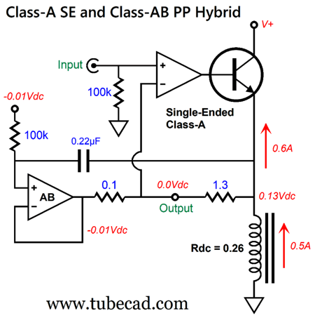
The triode is configured as a cathode follower. The output transformer's winding ratio of 1:5 implies a current ratio of 5:1 and voltage ratio of 1:5, so the 100mA triode idle current becomes magnified by fivefold at the secondary (500mA), but the cathode voltage swing is reduced by fivefold. The impedance ratio is equal to the winding ratio squared or 1:25, so an 8-ohm loudspeaker attached to the secondary appears as a 200-ohm load on the primary. But the loudspeaker also attaches to the impedance multiplier circuit, so the 8-ohm load becomes a 112-ohm load at the secondary and a 2.8k load at the primary. Since we lost the constant-current source, the efficiency of the single-ended output stage almost doubles. (The triode's current conduction is limited by our self-imposed restriction of not entering positive-grid current, so the triode can never match the NPN transistor's efficiency.) My next thought was that we could retain the NPN transistor and still lose the constant-current source by using an inductor.
This arrangement presented the problem of the inductor's DCR (the winding's DC resistance), which creates a large DC offset with the 0.5A current flow. My workaround was to allow the class-AB amplifier to produce a negative DC offset voltage to the inductor's positive DC offset by drawing -100mA of current though the two-resistor string. This explains why the inductor only sees 0.5A of current flow while the NPN transistor sees 0.6A of flow. My next idea was that we could use a center-tapped inductor and half the single-ended idle current flow but with a single-ended B+ voltage twice that of the class-AB amplifier.
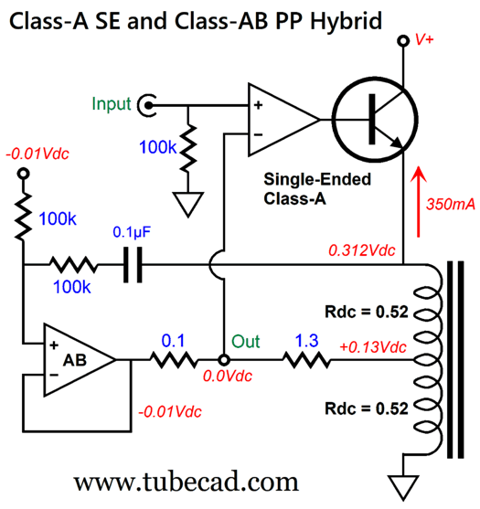
The center-tapped inductor forms an autoformer halves the gain at the center-tap, but reflects four times the impedance to the single-ended NPN transistor's emitter. I still wasn't happy. Why not? I didn't like that the class-AB amplifier and the single-ended NPN transistor were extra burden by having to null the DC offset. This got me thinking about alternative arrangements that didn't tax the class-AB amplifier's output stage.
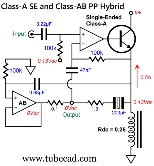
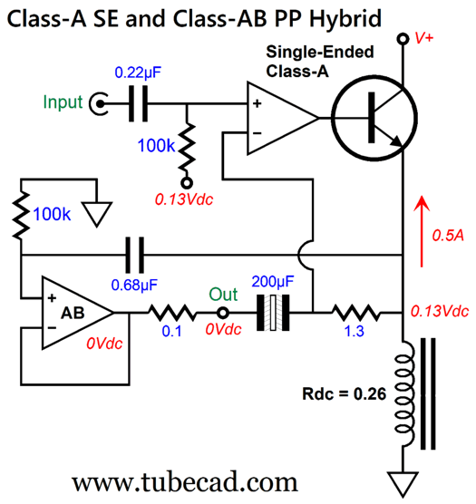
The SPICE simulations were not nearly as stellar as before due to the phase shift introduced by the 200µF output coupling capacitor. In addition, the circuit just held too many coupling capacitors for my taste. I realized that by moving the parts around I could eliminate one coupling capacitor.
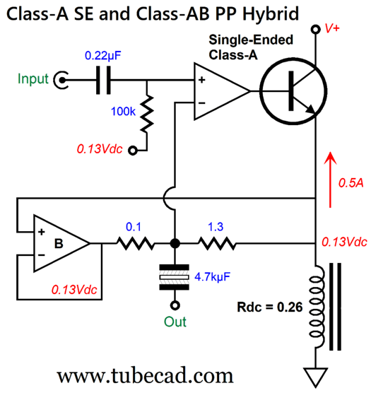
By the way, note that the 200µF output coupling capacitor seems to imply a 100Hz low-frequency cutoff with an 8-ohm load. Not so, as the impedance multiplier functioning makes the 8-ohm load appear as a 112-ohm load to the coupling capacitor. I finally decided to bite the dang bullet and place the output coupling capacitor outside the negative feedback loops, which meant that I had to use an appropriately huge output coupling capacitor. (Do not forget 4-ohm loads.)
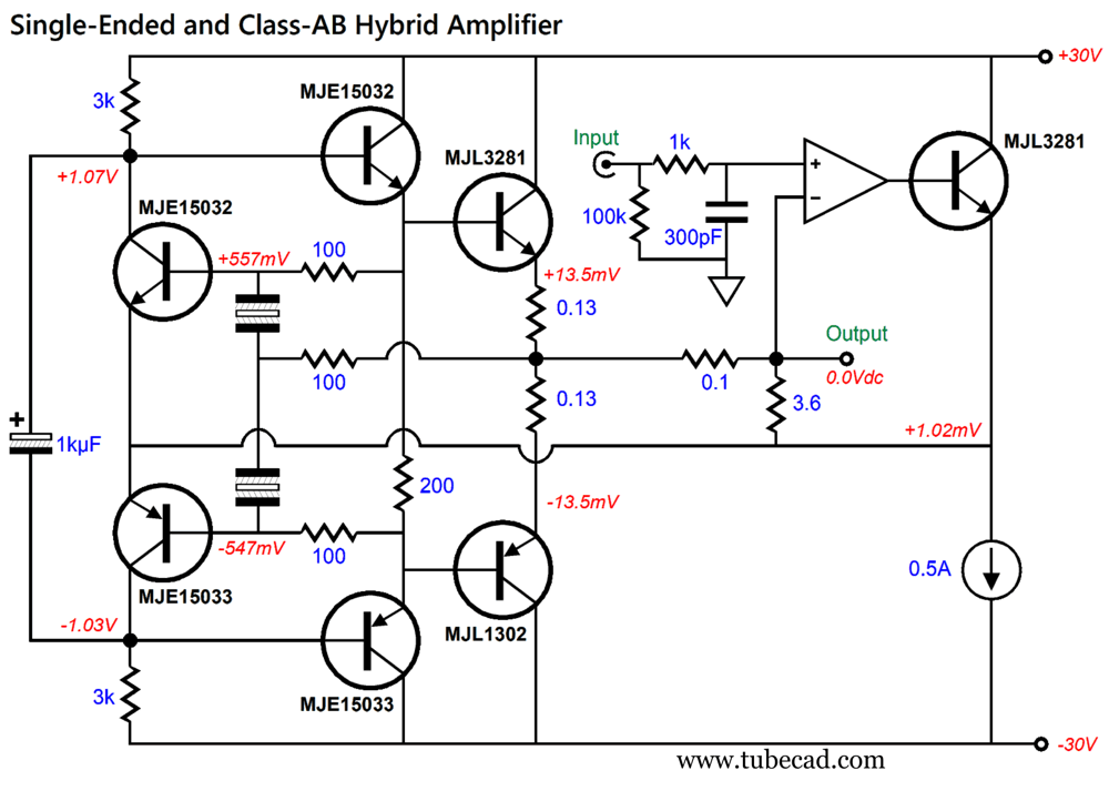
Note that at idle, no current flows through the 0.1 and 1.3 ohm resistors; therefore, the 0.13V DC offset from the class-AB amplifier doesn't matter, as its output transistors still do not conduct at idle. My mind returned to the inductor-free design with the LM3886. I deemed it a shame that its input signal had to be attenuated and then amplified. What if I devised a simple unity-gain buffer with auto-biasing of its output devices?
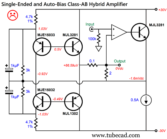
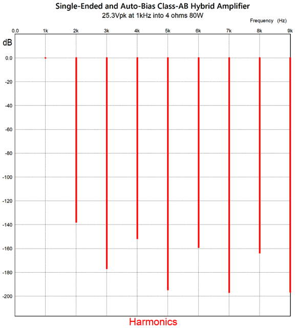
Note that the 4.7k resistors must be matched, as they set the idle current through the output transistors. Also note the absence of emitter resistors on the output transistors, MJL3281 and MJL1302. The assumption here is that all of the buffer's transistors are mounted on the same heatsink and close to each other, so that they heat equally. This circuit worked brilliantly with just ten cycles of 1kHz signal at 25.3Vpk of output (40W into 8 ohms), but didn't work well after 1,000 cycles, as the 1kµF capacitors deleted their charge. My workaround was the following:
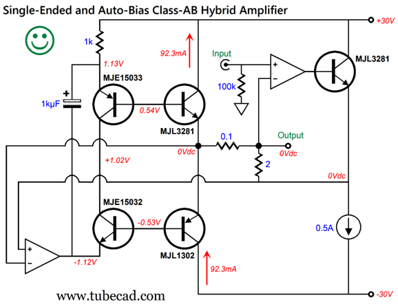
This class-AB arrangement exhibits a lovely negative temperature function:
The SPICE simulations showed a fabulous harmonic structure.
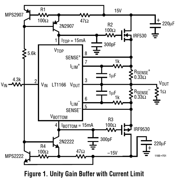
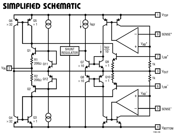
Another idea I had was that we could use MOSFETs in the class-AB output stage by using the LT1166 IC that auto-biases the output MOSFETs.
Did you note the 1-ohm load in the schematic? Inside the LT1166, the auto-bias and drive circuitry is fascinating—well, at least to me.
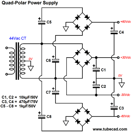
The problem with MOSFETs is that you won't get the same big output voltage swings that bipolar transistors deliver due to the MOSFET's much higher turn-on voltages—unless, that is we give the driver stage a higher bipolar power supply rail voltage. For example, in the schematic above, the LT1166 stage might get ±30Vdc power-supply rail voltages. This does not require a complicated power transformer, just a handful of rectifiers and capacitors. In the following schematic we see how we can get doubled bipolar power supply with a simple center-tapped secondary.
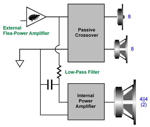
Still, I know this workaround would encounter mental opposition, so it was back to transistors. I recalled a power buffer circuit that I had created to be used in a powered loudspeaker system. The idea was that tube-based flea-power amplifier would drive loudspeaker midrange driver and tweeter directly, which would be high-SPL drivers, say 94dB/W, but the low-SPL woofer would be driven by the internal power buffer, which would allow using a DVC woofer with two 4-ohm voicecoils wired in parallel, making a 2-ohm load, thereby increasing the woofers SPL by 6dB. In other words, a 300B-based single-ended flea-power 9W amplifier would effectively deliver 36W to the woofer.
The internal bipolar power supply must be grounded to the flea-power amplifier's ground, which might create some grounding issues due to the possibly different house ground connections. Still, I think this a great idea. Indeed, if I had the wherewithal, I would be building it today. I would build the speaker stand as an integral part of the loudspeaker, not an accessory. In fact, the metal stand would hold the internal amplifier (buffer, actually) and serves as its heatsink. Okay, here is the power buffer circuit I had devised:
Note the ±30Vdc power-supply rails. Inside the loudspeaker, the rails could be as low as ±15Vdc, depending on how much power the flea-power amplifier put out. A nice subtlety would be power transformer with several primary taps, so the power-supply rail voltages could be adjusted to match the external power amplifier's power output. This buffer auto-biases the output transistors and exhibits a negative temperature feature, where the hotter the heatsink becomes, the lower the idle current becomes.
By the way, the temperature is in C. The distortion is surprisingly low, which the following Fourier graph reveals:
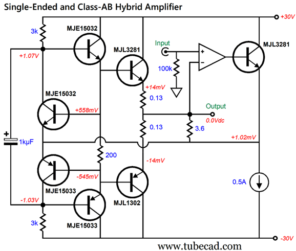
With the 8-ohm load, 27Vpk equals 45W of power delivery. Bear in mind that the buffer uses two negative feedback loops, but that neither extends to the output, as they stop at the middle driver stage. The downside to this power buffer is that its input impedance is low, 1400 ohms in this example, which is not a big deal when an external power amplifier, albeit a flea-power amplifier, drives it. If we plug it into the hybrid circuit, we get the following:
Note the absence of the 0.1-ohm current-setting resistor. In its place, the two 0.13-ohm emitter resistors and the buffer's failure to deliver true unity-gain effectively become the 0.1-ohm resistor. If we desire the extending the class-AB buffer's negative feedback loop to its output, well at least in AC terms, the following shows how it can be done:
Okay, let's plug this circuit, after one small modification, into the larger circuit.
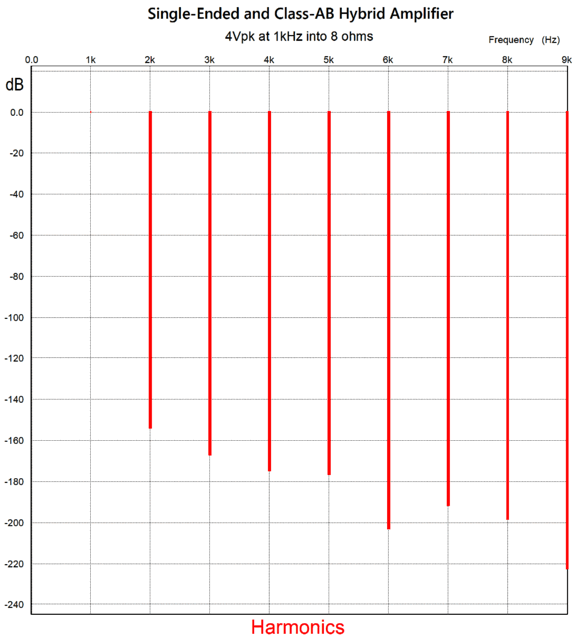
As I had to add the additional 100-ohm resistor to ensure high-frequency stability, the negative feedback returns only partial, relative to the output, as the output signal mixes with the signal from the MJE15032 and MJE15033 emitters. This results in less than unity-gain at the output. The RC high-pass filter formed by the input 1k resistor and 300pF capacitor limits the high-frequency bandwidth to about 300kHz, which is plenty high enough, as few audiophiles can hear above 200kHz ;) How well does this variation work? Here is the Fourier graph for 1W of output into an 8-ohm load:
Yes, this is about as low distortion as you can get, even in SPICE simulations, but it does not attain to "astoundingly atypical," sadly. Yes, sadly, because we weren't seeking just low distortion, but certain corrective distortion. As I have been writing this post, I have been haunted by some memory of my having stated before here that we seek the inversion of the typical push-pull sonic signature, as two wrongs can make a right. Google came to the rescue. From Post 621:
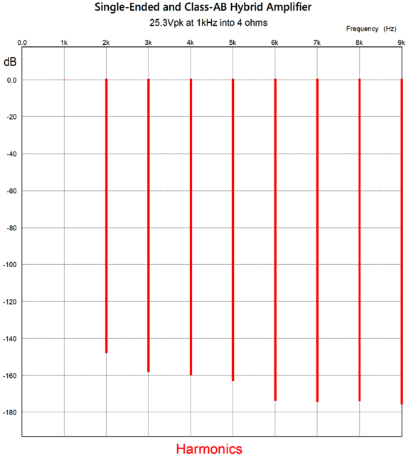
Here is the graph for full output, 80W into a 4-ohm load:
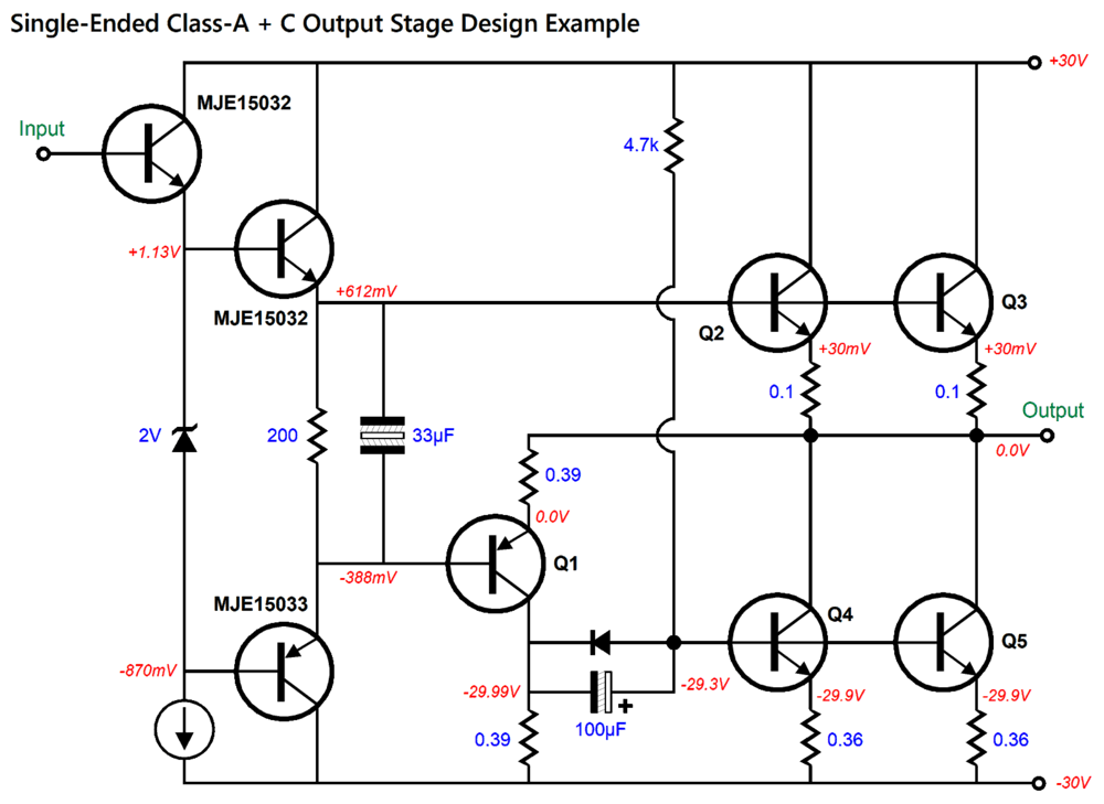
Once again, very clean, but not astoundingly-atypical. What went wrong? The problem lies in what went right. The class-AB output stage didn't produce a push-pull harmonic structure, but rather something like a single-ended harmonic structure. What is needed is the purest-push-pull sonic signature combined with and under the control of the single-ended output stage. While searching for previous circuits that I had devised that exhibited the astoundingly-atypical harmonic structure, I found this one from Post 582, which combines single-ended with class-C.
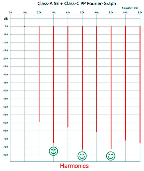
The way this output stage works is that transistors Q2 and Q3 operate in single-ended class-A up to a certain negative output voltage swing, thereafter they along with Q4 and Q5 function in a push-pull mode; up until that transition point, Q4 and Q5 function as constant-current sources. The class-C enters the picture with transistor Q1, which is turned off at idle and only turns on when the output swing sufficiently negative. With 36W of output into an 8-ohm load, we get this Fourier graph:
The THD isn't nearly as low as it was in that last variation, but it is astoundingly-atypical. One conclusion we can draw is that the LM3386 should not be used as the class-AB output stage; instead, we should stick to something more push-pull saturated, more class-B in nature, such as my earlier variations. In other words, the one lesson a reader show learn is that the last circuit shown may not be the best circuit. I have received grumbling complaints along the lines of, "Why don't you just show what the best circuit is and ignore all the others?"
Answer: best for what? Best in terms of low-cost? Best in terms of high-cost? Best in terms of thumping bass? Best in terms of elegance? Best in terms of low-power consumption? Second answer: you do not seem to get what my role is here. My task is to do the jobs that, apparently, only Americans will and can do, i.e. innovate with wild abandonment and rejection of prevailing customs and constraints. Elon Musk, by accident was born in South Africa, but by purpose he became an American, as Elon could not be Elon anywhere else. Of course, innovations occur in other places, but not with the same mad volume, exuberance, and recklessness of America. Who but an American would be so audacious to strive to make 1,000 posts filled with novel circuits?
Music Recommendation:AUDIOPHILE SOUND TEST
//JRB
AI Summary This document discusses harmonic distortion in audio amplification, particularly comparing single-ended and push-pull circuits, and explores methods for correcting harmonic structures using SPICE simulations and analogies. Exploration of Harmonic Enrichment in Audio Circuits Harmonic Distortion and Sonic Perception
Visual Analogies for Sonic Signatures
Circuit Design for Harmonic Correction
Practical Implementation and Simulation Results
Philosophical and Cultural Reflections
Music Recommendation and Listening Experience
Did you enjoy my post? Do you want to see me make it to post 1,000? If so, think about supporting me at Patreon.
User Guides for GlassWare Software
For those of you who still have old computers running Windows XP (32-bit) or any other Windows 32-bit OS, I have setup the download availability of my old old standards: Tube CAD, SE Amp CAD, and Audio Gadgets. The downloads are at the GlassWare-Yahoo store and the price is only $9.95 for each program. So many have asked that I had to do it. WARNING: THESE THREE PROGRAMS WILL NOT RUN UNDER VISTA 64-Bit or WINDOWS 7, 8, and 10 if the OS is not 32-bit or if it is a 64-bit OS. I do plan on remaking all of these programs into 64-bit versions, but it will be a huge ordeal, as programming requires vast chunks of noise-free time, something very rare with children running about. Ideally, I would love to come out with versions that run on iPads and Android-OS tablets.
|
I know that some readers wish to avoid Patreon, so here is a PayPal button instead. Thanks. John Broskie
John Gives
Special Thanks to the Special 90 To all my patrons, all 90 of them, thank you all again. I want to especially thank
I am truly stunned and appreciative of their support. In addition I want to thank the following patrons:
All of your support makes a big difference. I would love to arrive at the point where creating my posts was my top priority of the day, not something that I have to steal time from other obligations to do. The more support I get, the higher up these posts move up in deserving attention.
If you have been reading my posts, you know that my lifetime goal is reaching post number one thousand. I have 367 more to go. My second goal was to gather 1,000 patrons. Well, that no longer seems possible to me, so I will shoot for a mighty 100 instead. Thus, I have just 9 patrons to go. Help me get there. Thanks.
New URL of the GlassWare website |
||||


| www.tubecad.com Copyright © 1999-2026 GlassWare All Rights Reserved |